Old computers: repair notes
This Web page last updated Jul 4 2025. copyright (C) Herb Johnson 2025.
This Web page has some accumulative notes and images about repair of vintage computers.Check
out some of the repair issues below. Also, here some links to other vintage computer repairs and repair resources. - Herb Johnson
Introduction
There are unique challenges to repairing digital electronics of the 1970's and 1980's. Many of those challenges WERE well-known problems about computers of the period. Now in the 21st century, they are "lost history" I'll try to illustrate some of those solved-problems here. But some examples here are not computers; repair is just a good idea. - Herb
"Why don't you index your Web site?" Because Google is your friend. I suggest you use Web search, to find pages and things of interest to you on my Web site. Just do a Web search on the topic of interest, and add the phrase site:retrotechnology.com. The powerful search engine - which already knows what YOU like! - will find relevant pages on my Web domain. OK? That's why I don't have an index of all my Web pages.
..but here's some links and notes anyway.
shorting capacitors
blown traces
reforming big power supply capacitors
problems with rust, black IC pins
Cross Assembly, File Transfers to IMSAI
pulse generator as 8080 clock source
early Altair 8800 design issues with links to this Web page.
reverse engineering a S-100 schematic
reading and replacing 2708 EPROMS with 2716 2732
issues with 2716 EPROMs
those little fusable-link PROMs
Les Bird on Heath H-8 connector and disk recovery problems
how I fixed my refrigerator
repairing of a capacative-key keyboard
counterfit, mismarked, fake ICs
links to other repairs and repair resources
![[burned circuit trace]](h89_trace.jpg) I'm going to describe the consequences of a common problem with computers of the 1970's and 80': shorted tantalum capacitors which catch fire. Pictured on the left is a portion of a Heath/Zenith H89 computer board. I'll explain the image soon, but first let me describe what happened and what I did.
I'm going to describe the consequences of a common problem with computers of the 1970's and 80': shorted tantalum capacitors which catch fire. Pictured on the left is a portion of a Heath/Zenith H89 computer board. I'll explain the image soon, but first let me describe what happened and what I did.
In March 2005 I decided to get an old H89 out of years of storage and into operation. After dusting and cleaning, I considered what I might
do before powering up. A common problem on 1980's digital systems is that the tantalum
capacitors - the little gumdrop-like device on the board which filter the various DC
regulators - will short. The tantalum grows crystals which puncture and short the capacitor. When you apply power, all the current goes through the short. So the short typically ignites and smokes and burns. Some people find this a diagnostic method. They allow these caps to get "blowed up" and then find and replace the charred remains. There's problems with that method, as you'll see.
Other people, usually including me, will use an ohmmeter and capacitance meter to look for shorted caps and to verify their values. Sometimes you have to remove one "leg" of the cap from the circuit to test the device. Shorts measure zero to a few hundred ohms. Replacement caps must have the same capacitance, and equal or higher voltage rating. Values for these caps are a few microfarads to a few tens of microfarads: voltages from 16V to 50V, some small multiple of the actual DC voltage in use.
Note: tantalum capacitors are polarized, they have a "+" mark for connection to the positive side of the circuit. Also, tantalum caps can't be "reformed" or fixed by gradually applying DC voltage from zero. That's an old fix for electrolytic capacitors from vacuum tube equipment decades earlier - that does not apply to tantalums, and generally is not a problem for equipment "only" a few decades old.
This day, I got brave and decided to use the "blowed up" test. Sure enough, with the BRIEF application of A/C power, I saw a curl of smoke, and smelled the usual smell of burned circuit board or capacitor. I figured I'd remove the offending circuit board and
find the bad component. Well....I removed the most likely of the two boards, given the source of the smoke, but I could not find the fried component! I DID find a shorted capacitor, uncharred and on the wrong part of the board, and replaced it. Since I could not find the smoking source on ONE board, I checked the other board, the H89 computer card. No shorted caps there...no fried components....
I needed more clues. So I reassembled the boards and powered up again, and KEPT power on. In due course, the CRT showed a cursor - a good sign for the terminal board. But there was no response on the keyboard. The simplest tests then are: does each regulator produce the correct voltage? MOst 1980's digital board have one or more on-board regulators, and the terminal and computer cards are no exception. Sure enough, one of the negative regulators on the computer card had no input or output voltage! But the DC power supply was producing reasonable outputs. That meant something was interrupting the unregulated DC; or the regulator was shorting it out. But the regulator, a T0-220 device, was COLD, so it was not shorted.
The next step is to trace the circuit back from the regulator. I pulled the card to do just that. Then I noticed the board area which is photographed on the left. See the three bright vertical bars? Those are three circuit board copper traces, covered with a insulating but translucent coating. The fourth, dark vertical bar is - or rather was - another copper trace, only it has pulled up off the board and is curled over to the left, from the top and from the bottom of the image. That is what caused the smoke. The short did NOT destroy a component, it conducted enough current to use the circuit trace as a fuse! I've seen this before, as these old digital power supplies produce AMPS of current which will fry even a strip of copper.
This is why it's preferable to test for shorts with an ohmmeter, instead of your power supply. Fortunately this trace is repairable, by soldering a length of wirewrap wire across the broken trace. If this were a multilayer card, with power traces inside the circuit board, I'd be obliged to bridge the gap between two junctions. I got lucky this time. Bu I still have to find the short that caused the "'splosion".
Herb Johnson
Why tantalum capacitors?
It's been suggested that when a tantalum cap shorts out, you can simply remove (the carcass) from the board and the circuit "will still work".
While that may be true, it's not correct and it WILL cause some problems you won't easily detect. Here's some design reasons for tantalum and other capacitors. - Herb Johnson
Tantalum caps are there to provide DC power regulation, believe it or not. While they are small, in the tens of microfarads, that's enough to handle changes in DC "load" due to millisecond power demands. When that section of a digital circuit, or that board in a multi-board system, becomes "active", it draws power and that will dip the DC voltage if the cap is not there. When on a voltage regulator, they "isolate" the circuit at that point, from OTHER changes elsewhere in the system.
These larger caps WON'T filter microsecond noise, the power surges and induced currents from megahertz-switched logic circuits. That's why there are ALSO "bypass capacitors" in the .1 uFd range throughout digital circuits. At those speeds, every wire is a capacitor, an inductor AND a transformer. Digital wires are full of noise, digital chips generate noise. That's what the small bypass caps get rid of. The bigger tantalum caps have too much "impedance" at megahertz speeds to do that.
Any book in the last 40 years on digital design will describe this stuff. The reason 30-year-old computers work at all, is because their designers paid attention to this stuff. Conversely, designers in the era who did NOT pay attention to this stuff, produced boards that did not work WHEN SOLD.
As to why tantalum caps instead of other kinds? Tantalums are smaller than conventional "electrolytics". But they have the habit, over years or decades, of growing little metal crystals of pure tantalum. These puncture the insulators (dielectric) between the tantalum "plates", creating shorts. The shorts draw amps of current and the cap blows up. Electrolytics don't have this failure mode.
![[burned circuit trace]](extend_trace.jpg)
A colleage of mine, Jonathan Chapman, showed a dramatic photo of a blown circuit trace, in a discussion group on Jan 2014. He posted: "Ever forget that the tab on a [7908 TO-220] negative voltage regulator /is not/ ground? The IMSAI's power supply let the smoke out of the extender board!" The photo of the S-100
extender card is shown here on the left. The second line from the end is the -18V line on the S-100 bus. when shorted to ground at the extended connector, the extender becomes what is technically called a "fuse".
I asked if I could add that photo and description to this Web page. He agreed, saying
"it's good for people to see just how easy it is to actually blow traces off a board, even for someone who knows better!" He described the situation this way. "That board had been powered up several times for various testing before the 7908 regulator arrived. Fortunately it was still in the extender, or I'd have lost a backplane or board trace, as my IMSAI's power supply isn't fused on the [AC transformer] secondaries."
Electronics in the 1970's and earlier, often used large capacitors in the DC power supply. They were
large because they needed a lot of capacity to reduce noise and AC ripple in high-current low-voltage power supplies.
These ran at power-line frequency of 60Hz (50Hz in Europe); then transformers, diodes and capacitors produced DC voltages. But after years and decades without power, the electrolytes in the capacitor lose their "form". If full power
is applied, the capacitors won't have the capacity to regulate, and they will need to be replaced.
But if DC voltage is applied at a low value, and raised up to rated voltage over a period of time, the
caps will "reform" and often can be restored to normal use. This is not always the case for some kinds of capacitors.
You will have to do further research for more details. To create low DC voltage, on these old power supplies, one
uses a "Variac", which is a trade name for a variable voltage transformer. WHen sending the AC line voltage through
a Variac, you can start at a low voltage and manually adjust to a high AC voltage.
Old power supplies with large capacitors and transformers are called "open frame" or "non-switching" power supplies.
The reference to switching, refers to power supplies of the 1980's and later, which created high-frequency AC power
from 60-cycle (50-cycle in Europe) AC power by rapid switching DC voltage. High frequency uses smaller capacitors and
smaller transformers, which save weight and size. And, they regulate the AC, and the DC, adjusting for different
AC line voltages. Also they adjust for their DC loads; some require a minimum load or they get out of adjustment
range and can damage themselves.
Because of the adjusting circuits, the need for a load, and the smaller capacitors they use, these "switching power supplies" are not candidates for "reforming" by controlling their AC input power with a Variac. Either one replaces
these electrolytic capacitors, or you remove or disconnect them and "reform" them with a variable DC power supply.
During this SWTPC 6800 computer repair, I reformed the capactors with a Variac, after pulling out most of the computer boards inside. It has a small and simple AC line based power supply.
On this S-100 class Problem Solver System computer, I reformed
the capacitors on the chassis power supply. Also I checked the S-100 boards for shorted tantalum caps.
See the "power-up" section for photos of the Variac and the power supply. See how I monitored the DC voltages
as I raised the AC voltage. Again, on these simple supplies, the DC output is proportional to the AC input.
In 2013, I restored a PDP-8/F minicomputer including reforming
the caps on its 1970's power supply. This effort was more elaborate, thanks to the tools provided by
David Gesswein, who has restored several minicomputers. So an external variable DC power supply was used
to reform those individual caps, unwired from their power supply.
Rust occurs when there is water or moisture on metal for some sustained period. Sitting in humid conditions for
years can really build up rust in vintage computers. Also, there's the "black pins" of 1970's ICs from Texas Instruments (TI).
Also, there's occasional use of steel-based IC pins, which rust out. Here's brief notes on these matters. - Herb
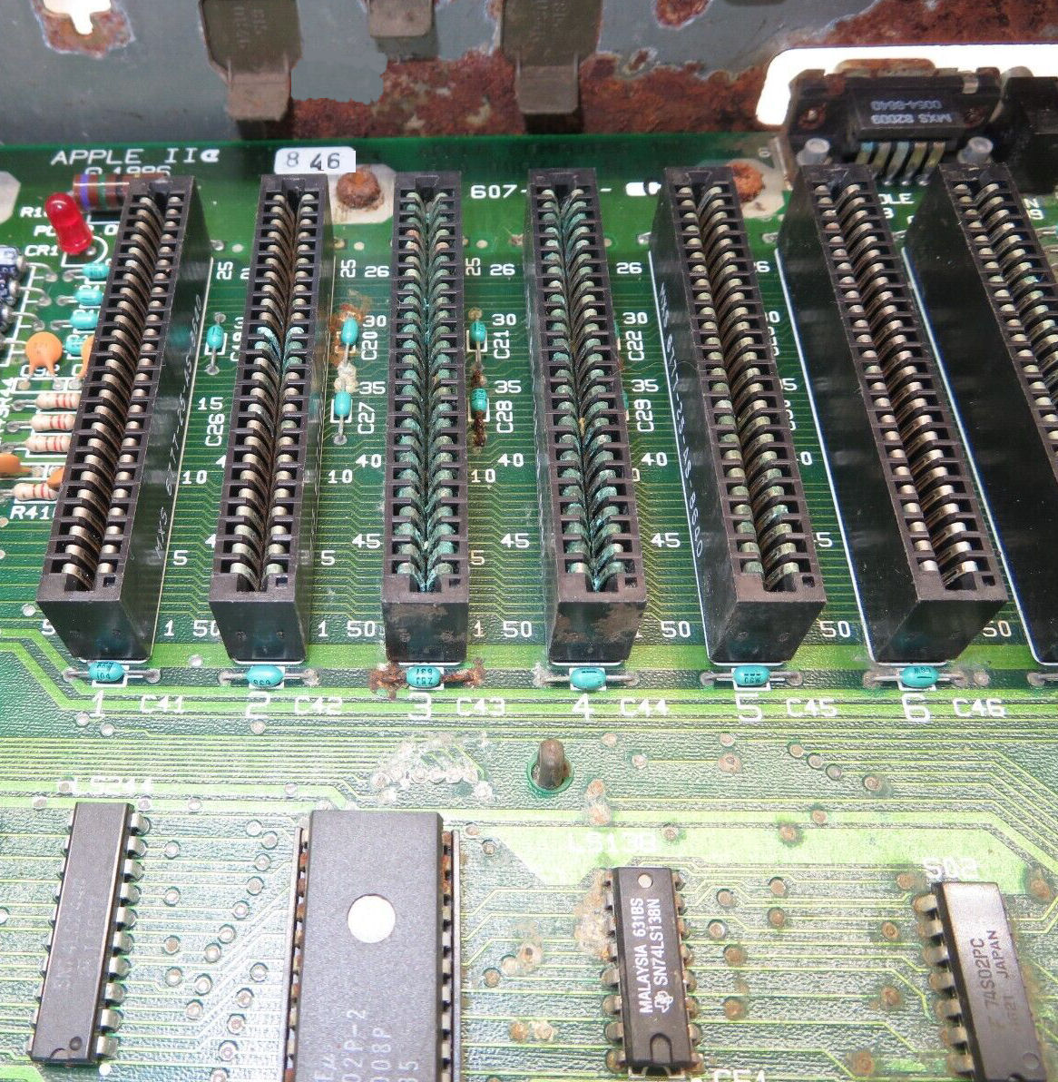
Here's a sad Apple IIe that shows
multiple kinds of rust. The blue rust on the edge connectors, is blue because it's copper oxide. The rust got under the thin gold or bronze coating to the copper. Cleaning that off, won't restore the gold. The red rust is
iron oxide; mositure got inside the steel case under the grey paint. Blue or green rust is copper oxide. Note, some of the component wires are red - steel wires. Same with the screws, rust under the zinc coatings. Even the PC board "thru-holes" are spotted with rust, the lead and tin become red and white. Same with the IC's and sockets, their copper pins. This is a really sad circuit board and computer, hard to know if anything is salvagable.
Localized metal rust can be scraped, sanded, and repainted. For metal surfaces of size, I use "Bar Keeper's Friend" which is a light abrasive
(ground pumice) and has some alkaline qualities to neutralize the acids that sometimes lead to rust. There's contact-cleaners and restorers including "DeOxIt" brand. Sometimes rusty solder joints can be resoldered. But sometimes you have to discard a chassis and use another chassis, or salvage less-rusty boards and components.
Modern Web search about these subjects, will not find many vintage computing references. "black oxide" finds a chemical method to protect bolts and nuts, an anodize process. Also "black foam", when degraded old black antistatic foam rusts up chips (likely
due to sugars and moisture in that antistat material). Sometime in the 2020's TI produced "roughened leadframes", a production change of DIP IC pins that produced a non-shiny surface; they claim it improves solderability.
"black pins" of 1970's TI ICs
Texas Instruments produced logic ICs in the 1970's, which pins tended to form a layer of "black rust" or corrosion or discoloration. It was/is unsightly, and may produce bad connections in IC sockets. The diagnosis and appearance info about this
problem has fallen off the Web in the 21st century, but was well known in the 1980's and 90's. I have examples of
this problem, when I restored two Ithaca Intersystem DPS-1 S-100 systems.
The general claim from the era, is that the black is silver oxide, essentially tarnish. They say it's due
to TI's use of a silver plating on their IC pins, for a period in time in the 1970's. Some claim the
tarnish does not cause poor IC socket connections. Sockets have their own issues about corrosion and contacts.
Various suggested means of cleaning were to abrade (scrap, sand) the pins and retin with solder, or use
some silver-cleaner followed by alcohol and/or water. Soldered ICs with this black-oxide are apparently not an issue.
I don't have a definitive fix, other than replacing the IC's. If I find a fix I'll update this Web page.
Rusty, blackened IC pins
Here's a reference from the era by "hilpert", a Canadian email address,
from 2014 in the classiccmp.org email list on vintage computing. It covers both black-pins and steel pins.
Some plastic TI TTL ICs from a period somewhere around the mid/late-70s were manufactured
with steel pins that corrode underneath the plating. They might look fine but simply fall
off with the slightest stress, or develop intermittent conductivity.
I think the TI steel-pin rot is the only wide-spread IC fault I've really correlated
to a particular manufacturer/period, and I don't know whether it was company-wide or
production that came out of maybe just one of their plants. (It can occur with other
manufacturer's steel pins but then it seems to be more a result of particularly bad
environmental/storage conditions of the machine and not really a surprise.)
But with that said, a lot of TI ICs from around then [otherwise] show [black] discolouring on the pins that
looks horrible and suspect, but the discolouring doesn't necessarily imply the
corrosion underneath. I believe the visible discolouring was (often) just oxide of the
silver final plating of the pins. It shows up on TI because they were the only ones doing
that plating.
One of my customers, Denver Hull, was working in 2008? on his IMSAI 8080 with SD Systems Versafloppy II and IMSAI SIO serial card. He describes below how he assembles code on a non-CP/M system and moves code to the IMSAI using a simple serial program to run the SIO card. The "remote" system is running Unix NetBSD; but the same applies to any Windows or Mac system which supports an 8080 emulator or cross-assembler and a simple telecom or file transfer program. - Herb JOhnson
"My Imsai has an original 8080 processor. I understand that that's probably only going to be fast enough for single density, but that's ok (I also have an old Multitech MIC-501, not S100!, with SSSD 5.25 disks). I do have a Cromemco ZPU 2/4 MHz processor card, but it behaves oddly when I plug it in, so that's another project for later."
"Essentially I'm bringing this up from scratch - I have no other S100 system available with disks. But I have CP/M on the MIC-501, and I'm running simh (altairz80 with CP/M) on my FreeBSD systems. I've written a short program that I can toggle into the Imsai. It transfers binary files through the RS232 port to any location in RAM. Works quite well with cu on a UNIX system. I even echo the lower byte of the destination address on the IMSAI front panel so I can see when it's done, and if it finished in the right place. I can probably do the same thing in the other direction, but haven't needed to, yet."
"[The serial connectors] are all pretty standard stuff. I didn't have to do anything special for that part - the SIO2 is jumpered with the default configuration from the manual. Currently, it's connected to an sgi O2, but it could just as easily go to a PC. I made the two internal cables. They're straight through, like it shows in the manual: 25 pin D on one end, 26 pin edge on the other, with 25 conductor ribbon cable between. Skip pin 26 at the [SIO2] edge connector....
Here's the code to do the RS-232 transfer:
E100                   ORG     0E100H          ; INITIALIZE THE SIO PORT
E100 3EAA              MVI     A,0AAH          ; DUMMY, SO WE CAN
E102 D303              OUT     03
E104 3E40              MVI     A,40H           ; RESET IT
E106 D303              OUT     03
E108 3ECE              MVI     A,0CEH
E10A D303              OUT     03
E10C 3E37              MVI     A,37H
E10E D303              OUT     03              ; GET WHATEVER THE OTHER SYSTEM SENDS
E110 110000            LXI     D,0000H
E113 DB03      LOOP:   IN      03
E115 E602              	ANI     02
E117 CA13E1            JZ      LOOP
E11A DB02              IN      02
E11C 12                STAX    D
E11D 13                INX     D
E11E 7B                MOV     A,E
E11F 2F                CMA
E120 D3FF              OUT     0FFH
E122 C313E1            JMP     LOOP
E125 				END
"It's a little bit long, but not too bad. You have to change the address at E110 to fit whatever you're loading, of course. Here's how it works:
1. First, you need to get the program you are working on into a plain binary format that isn't offset somehow. I use CP/M's ASM to produce an Intel hex file. Then I transfer that to a FreeBSD system and use objcopy: objcopy -I ihex -O binary infile.hex outfile.bin
2. Have the CP/M system (Imsai, in my case), connected to an appropriate RS232 port on a Unix system that has access to the binary file you just created.
3. Run cu on the Unix system, with appropriate parameters. In my case, I use: cu -lttyd2 -s9600
4. Toggle in the above code and start it running at e100.
5. In the cu window on the Unix system, type: ~$cat outfile.bin (you could probably use ~| to go the other direction).
6. The Programmed Output LEDs on the Imsai will blink until the transfer is done. They should end with the lower byte of the last address of your program plus one.
"The only real problem with this is with programs that are mostly located at the upper end of memory, but have a few things ORG'd at the lower end. What you end up with then is a large binary file, with lots of zeros in the middle , that will probably wipe out the loader. You could break something like that up into pieces to get around that problem. In fact, it would probably be easiest just to split up the .HEX file.
"I've found that using SIMH on the FreeBSD system to run CP/M to assemble programs works quite well. The Altair Z80 simulator and CP/M that comes with it contains two programs: "R.COM" and "W.COM" that make it extremely easy to move files between the host filesystem and the emulator's CP/M disk file(s). A typical edit/assemble/load process would go like this:"
1. Edit the file with your favorite Unix editor, vi perhaps, and save it. Make sure there's an embedded ^Z at the end. Save it wherever the emulator's disk files are.
2. I use unix2dos to add all the ^Ms to the ends of the lines. You may also need to do something to convert everything to upper case, depending on how forgiving your CP/M assembler is (in vi you can type: :g;[a-z];s;;\U&;g).
3. In the emulator's CP/M session, type: R PROGNAME.ASM. That copies it into the current CP/M disk. 4. Assemble it: ASM PROGNAME.AAA. Use appropriate drive letters for where you want the output files to go.
5. Transfer the .HEX file to the host filesystem: W PROGNAME.HEX.
6. Convert that to binary, using the host's objcopy: objcopy -I ihex -O binary PROGNAME.HEX PROGNAME.BIN
"Now you're ready to use my loader program and cu to squirt the code into the Imsai. You're probably wondering why not use the CP/M LOAD program? Well, LOAD isn't made for making a direct conversion from Intel Hex file to binary, so things don't come out quite right when you try to use it for this. At least that's what I found when I tried."
-- Denver Hull
[Note from Herb: CP/M's DDT will read a hex file and load binary in memory, which can be saved. One could write in 8080 assembler a hex to binary converter, or find such a program.]
Allison Parent regularly posts in comp.os.cpm about computers and software of the 1970's. In October 2006 in one of her posts she said: "For an experiment I once pulled the 2mhz [crystal from a MITS Altair 8800 CPU board] and ran off a pulse gen at rates as low as 10khz. It was very interesting then to see the 8080 marching along at dead slow." I asked her for details and she gave the account below. - Herb
"Actually the !@#$ crystal failed and I figured I can use the pulse generator to run
it; it just happened to be set low initially. It was quite interesting to
see the system cycle at the speed of molasses in winter".
"The pulse generator was an 8038 based signal source that would run up to
500khz as modified. If you want details it's the SWTP Function generator
modified for greater range and a few other improvements. I actually used
the square wave setting. It was coupled DC to the first input of the logic
osc used as the crystal osc. The 8800(early not even A) used a series
crystal with two 7404s biased as an osc, a poor circuit at best."
"This was done in the spring around March of 75. Age of the unit was not a
factor. At the time I also tried a few crystals from 2.0 to 3.0mhz. It
got flaky around 2.470 likely due to one-shot timing not scaled to clock."
"On a good day I'll conceeded that I learned a lot off that POS Altair.
However time spent dealing with a flaky system was not time spent
developing software or getting better at programming. I was thrilled
when I got the NS* Horizon as once it was built I was replacing solder with
assemblers and editors."
After Allison Parent's description of clocking the Altair 8800 with a pulse generator, I asked about her specific design issues with the Altair. She told me how early her Altair was, and then how she or MITS improved it. Follow this Web link to see her comments.
Reverse engineering is the art of creating a design from the actual item,
rather than creating a design to produce an item. In the S-100 world, reverse engineering
refers to creating a schematic by examination of the circuit board and parts. Here's how.
To create a partial S-100 schematic, trace with an ohmmeter, from the S-100
pins up into the board. You will need of course, documents for the individual IC's
on the board - mostly TTL logic and some mix of functional chips. And you'll need a S-100
signal list. I have three versions of that list on this S-100 bus Web page.
You can determine some things with little fuss. You can determine
if the card is a bus driver or driven by the bus. You can confirm what
DC voltages are needed from the bus. Of course look on the board for
voltage regulators to see if the bus DC voltages are regulated 5V 12V or
unregulated 8V 16V. And so on.
If your S-100 board is a bus-driver (formerly called a bus master), then the s-100 address lines will be driven - outputs of whatever chip-pins are connected to those lines. So trace the address line to chips and see what they are. If the lines go to inputs, the board is bus-driven (slave) so a memory or I/O card. Also look at address lines A16-23, if they are in use: if not, the board is old S-100 not so much IEEE-696. Also check the bus clocks, phase 1 and phase 2, see which ones are in use.
If you follow the bus status lines, you'll get a little more information. Follow the data lines to see if the board is 8-bit unidirectional or 16-bit bidirectional.
If the board has any ROM or RAM, that's good. See if you can decode the addressing, from whatever "enables" or "chip selects" to the addressing logic. If the board has any I/O devices, see if you can decode the I/O address. Some boards will use PALs for addressing, so you can't use simple ohmic testing; you'll have to write a program to race through RAM or I/O space to see which address enables those IC's.
While you are using your ohmmeter, check the tantalum caps for shorts. And trace the DC power lines from the bus, and look over the regulators. With luck you only need 5V (8V) but with serial you might need +/- 12V (18V) power. See if -8V is in use.
Of course: Dump and disassemble any ROMs. Disassembly will tell you where ROMs RAMs and I/O
are addressed on the board.
All this will get you somewhere; it will inform you about how to program the board; and
you will learn more about IC's and busses and functions. Good luck! - Herb Johnson Sept 2021
In a discussion of Northstar repair in comp.sys.nortstar, a poster referred to the following Web site Changing the 2708 game roms This site discusses repair of an old Z80 CPU gaming system, by replacing a 2708 with a 2716 or 2732 (5V versions only). Also, how to read (not program) a 2708 using a 2716 programmer. I'd be very very careful about adding -5V and +12V to a programmer!
(Summary: For adding a 5V 2716 to a 2708 socket, bend pins 19 and 21 upwards, wire 19 to ground, 21 to +5V. For adding a 5V 2732 to a 2708 socket, bend pins 19 and 21 upwards, wire 19 and 21 to ground.)
(For READING a 2708 on a 2716 programmer: bend pins 19 and 21 upward. Solder wires on to pins 19, 21 and pin 12. Set the programmer to 2716. POWER DOWN THE PROGRAMMER. Insert the 2708. Apply -5V to pin 21, use pin 12 as the ground for those voltage supplies. THEN AND ONLY THEN power up the programmer. then apply +12V to pin 19, use pin 12 as the ground. Read the EPROM. Then remove +12V, THEN AND ONLY THEN power down the programmer, then remove -5V. FOLLOW THIS ORDER AS DESCRIBED. )
The 2716 was one of the first 5-volt only EPROMs, with the exception of the TI brand TMS2716, which *was*
a 3-volt part. The TI TMS2516 was their 5-volt only part, deliberatly renumbered so it was distinct. Meanwhile
the rest of the IC industry produced 5-volt only "2716"'s. As the 2716's were early EPROMs, the earliest were
slower-speed parts, as in hundreds of microseconds. Thus the date of the part, and suffix on the part name as a dashed number
(2716-3, etc.) suggest the speed of the part.
Experiences I'm aware of, suggests that the 2716's degrade over periods of decades, moreso than other and later EPROMs.
Possibly it's due to degradion of the injected charge (do homework on how EPROMs of the 70's and 80's work) or maybe
degradion of processors, RAMs etc. in the microprocessor circuit. The speed factor also plays out when "dumping" EPROMs
using an EPROM reader/programmer: if the programmer tries to read some 2716's too fast, it will lose bits. The proper
speed setting or correct brand/model of EPROM setting, or an older/slower EPROM reader, may be needed to recover
the EPROM's data. (These issues are similar to issues with 1702's and 2708's as described on this Web page.)
From Allison Parent, July 2025 in
this groups.io cosmacelf discussion thread.
Read the discussion for further details and other people's experiences.
"I used a lot of 2716s in the 1979 to 1983 time frame and there's two things of note.
I had a lot of them fail (all FFs) and some that were not programmed by me.
Apparently it was not done correctly and the bits rotted, but the part
was still programmable. Seem if you don't program them correctly they
forget typically in less than 10 years. The spec however does not
guarantee forever."
"High heat (still in spec) tended to make them
go soft as well. It was a trick that parts that have been erased many
times for reuse, need a bake at around 50C for a day to revive them.
The other thing that drove me off them is [the availability of] 2764, 27128
and larger EPROMs, then CMOS versions."
"The 2716 was a slow part [early on]. Most were 450ns, and they made me nuts as Z80 at 4mhz was
a hair too fast for them. Worse with propagation delays for bus and decodes around
them."- Allison
More discussion of 2716 EPROMs, talked about heating or cooling the PROMs to see if flaky bits can be recovered.
Also, increasing or decreasing Vcc (5.0V to 4.75 or 5.25) on read to change the detection threshold of the EPROM cells.
Various "slow" and "fast" programming algorithms, Higher or lower Vpp programming voltage,
may inject more or less charge in the EPROM cells.
A discussion of Intel ICE-51
8051 emulator boards in Google Group "intel-devsys", provides some suggestions and details over all the topics
in this section on 2716 "bit rot" issues. They described detailed experiments on freezing and heating, and trying
different EPROM programmers with different timing. The "acid tests" are 1) to get consistent reads and 2) to see
the reads produce plausible codes and data without patterns that suggest a bit-position or memory-address problem.
Another similar discussion was in this intel-devsys thread. Herb
Herb Johnson
New Jersey, USA
follow this link to email @ me
Copyright © 2025 Herb Johnson