![[PSS S-100]](pss_deliv2.jpg)
Most recent revision date of this page, Aug 22 2016.
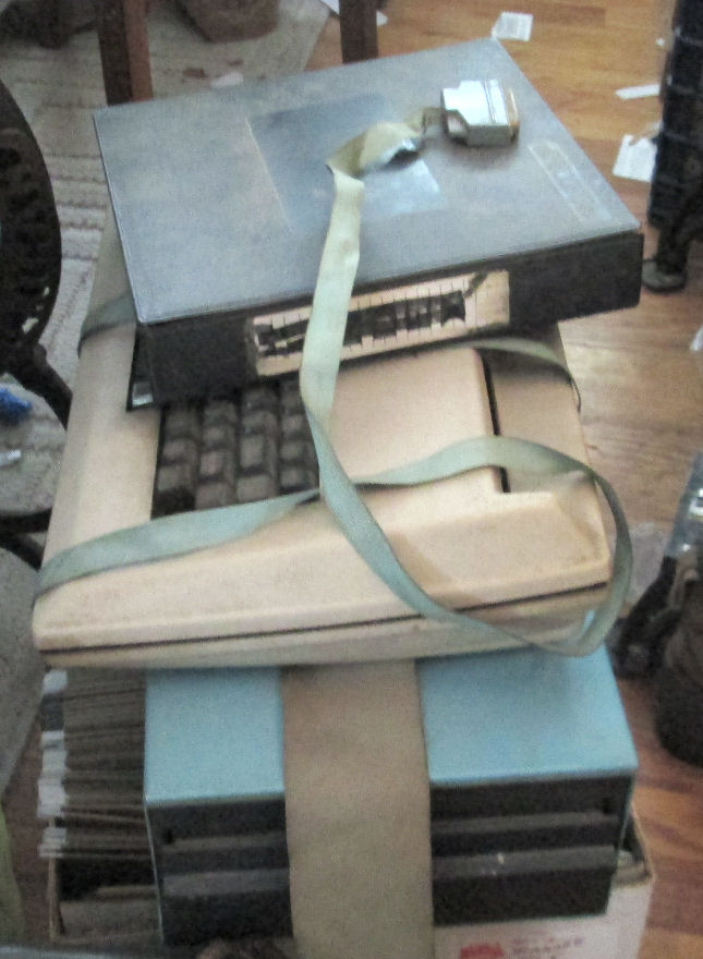
I recieved a PSS or Problem Solver System "Wizard" S-100 chassis and board set in mid-Aug 2016. I did some preliminary work on it at the Aug 20-21 2016 VCF Inc. repair workshop at InfoAge/VCF Museum in Wall, New Jersey. See this Web page link for details of that workshop and people there. This Web page discusses the history of this particular system and my work to get it running again. - Herb Johnson
   - 2 PSS (Problem Solver Systems) RAM 16 cards
   - North Star [ZPB-A1] Z-80A processor board
   - Microdiversions ScreenSplitter [video board]
   - Thinker Toys [Disk Jockey 1] floppy disk drive card (Copyright by G. Morrow)
   - Cromemco [TU-ART] I/O card, 2 Serial, 2 Parallel
   - in a PSS "Wizard" CM4800 S-100 bus chassis with PSS motherboard
The remaining accessories are a parallel-driven keyboard, maybe from Cherry; a single 8-inch drive (my guess Shugart 800); and a box of 8-inch diskettes single-sided. I recieved no documentation for the system or cards. But I had docs, or could get docs online, for everything but the Screen Splitter card. The motherboard and chassis aren't documented but only has connectors and traces; and fuses, caps and transformer. The rotating control on the front panel is a pot to the video card.
![[PSS S-100]](pss_dusty.jpg)
The chassis was dusty, but not too rusty. Rust was mostly limited to the transformer. A power vacuum blew out most of the loose dust, damp paper towels got the sticker dust.
Ohms testing: Each S-100 board was removed and examined briefly for issues, then a ohms check was done on DC input and regulator output. Ohms to ground would find any immediately shorted tantalum caps. They can of course, short on power. Ohms tests on regulator outputs are done such the meter's positive probe is put on the positive side of the DC circut (ground for negative regulators). Why? Because all the powered circuits will then measure "forward biased" at their minium resistance. TTL chips will produce several hundred to a few thousand ohms of "resistance", depending on the number of chips and TTL "family". It's a matter of experience to size this up. Clearly a very low reading suggests a short.
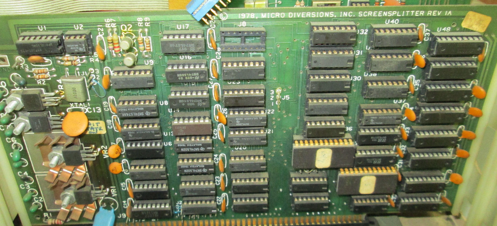
The Micro Diversions video card.
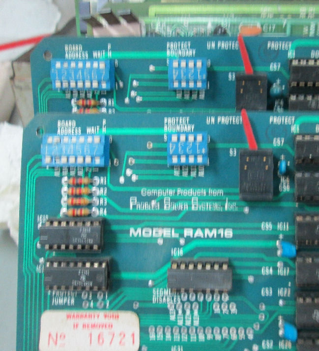
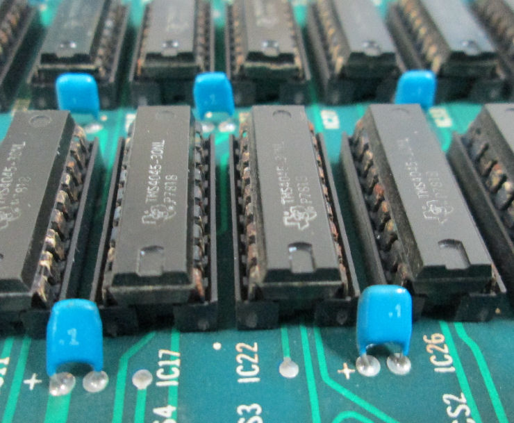
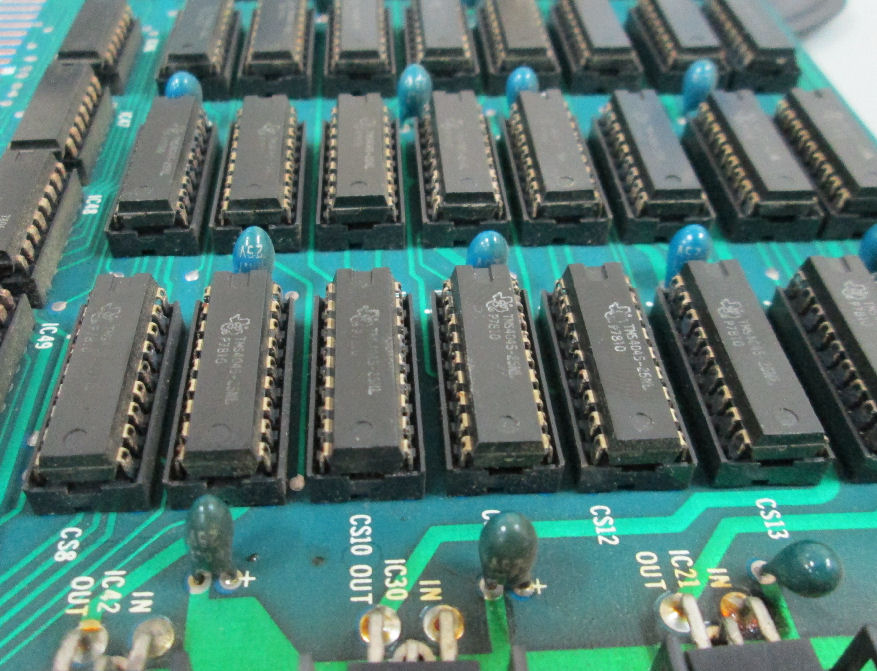
The two PSS 16K RAM cards - showing switch settings.One is set for 0000H, one 4000H. TMS 4045 RAM chips, 4K X 1 bit I think.
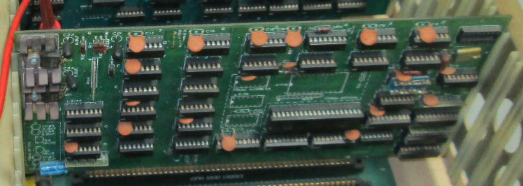
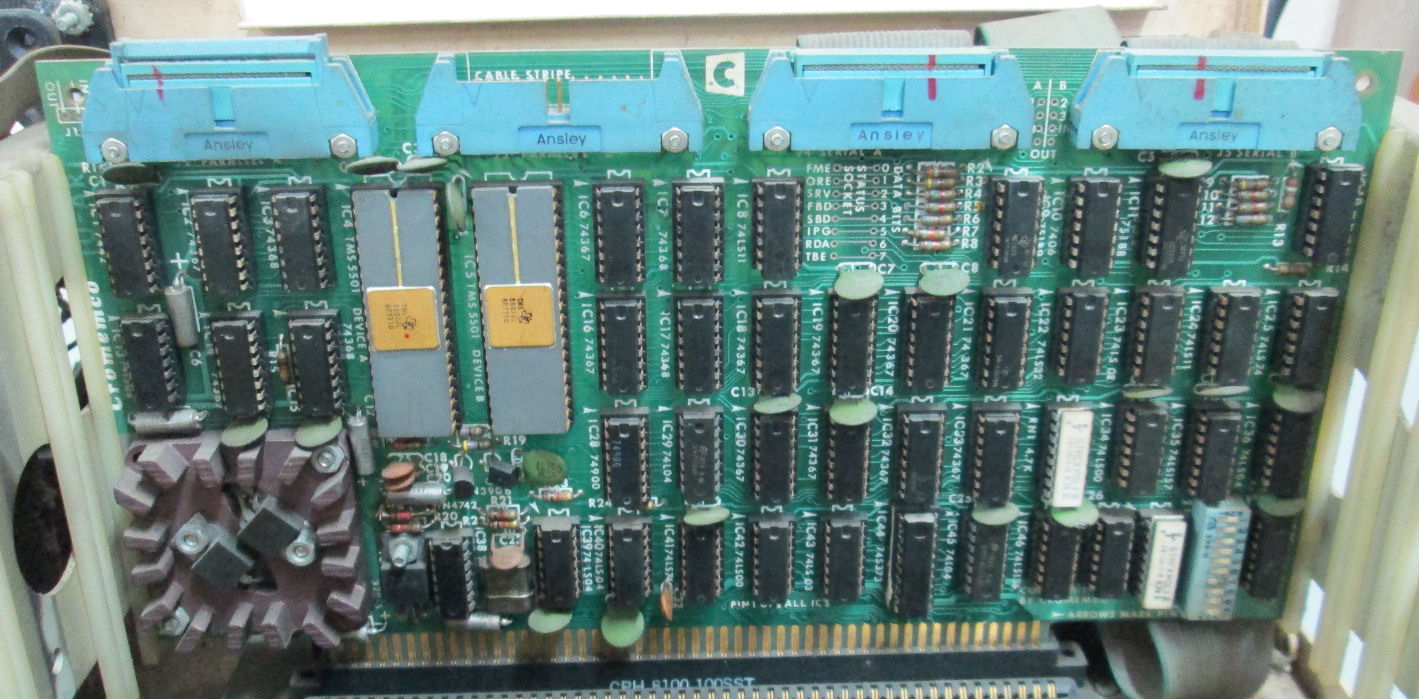
The Cromemco TU-ART serial/parallel board. For serial I/O and parallel to the keyboard. Note these are TI brand UARTS. Also note a nice touch: the red lines marking the connectors and cables "match" and are uniquely placed.
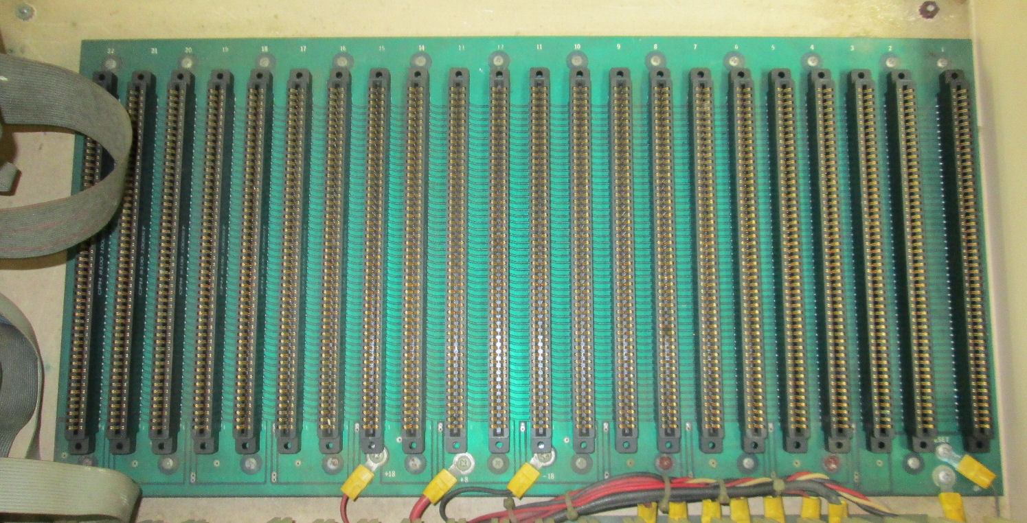
Here's the empty backplane, a PSS "" model.
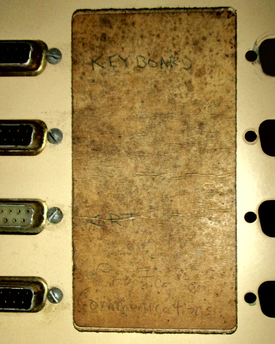
Cleanup and removal of cards, exposed the connections to the video connector on the back and my camera exposed the lable which identifies the connectors I'll have to sort out the video signals with an oscilloscope, as I have no docs.
One of the PSS RAM boards had normal bypass caps of .1uF around its TTL and memory chips. But oddly, the other PSS card used 4.7uF tantalums also as bypass caps! "Bypass" caps are usually .1 uFd, their response for "bypassing" high frequency noise is better than the 4.7uf caps. Either the factory screwed up, or parts were purchased and assembled by the purchaser. Also, those 4.7uF Tantalum caps are the ones which "flame on" under stress. I intend to replace them.
I asked, and previous owner Rich says "Both PSS memory cards were purchased assembled. While I did use a soldering iron back then, I know I didn't use one at all on this box with the possible exception of updating the Screensplitter card [video interface] after we'd been running for awhile. I would not have recognized that [capacitor value] error when we bought and set the system up. (I'm a software guy at heart.) The system really did run with those cards so I'm not sure what the story is with the bypass caps. Assuming they don't catch fire, I'd expect the system to work even with the wrong caps in that position."
![[PSS S-100]](pss_variac2.jpg)
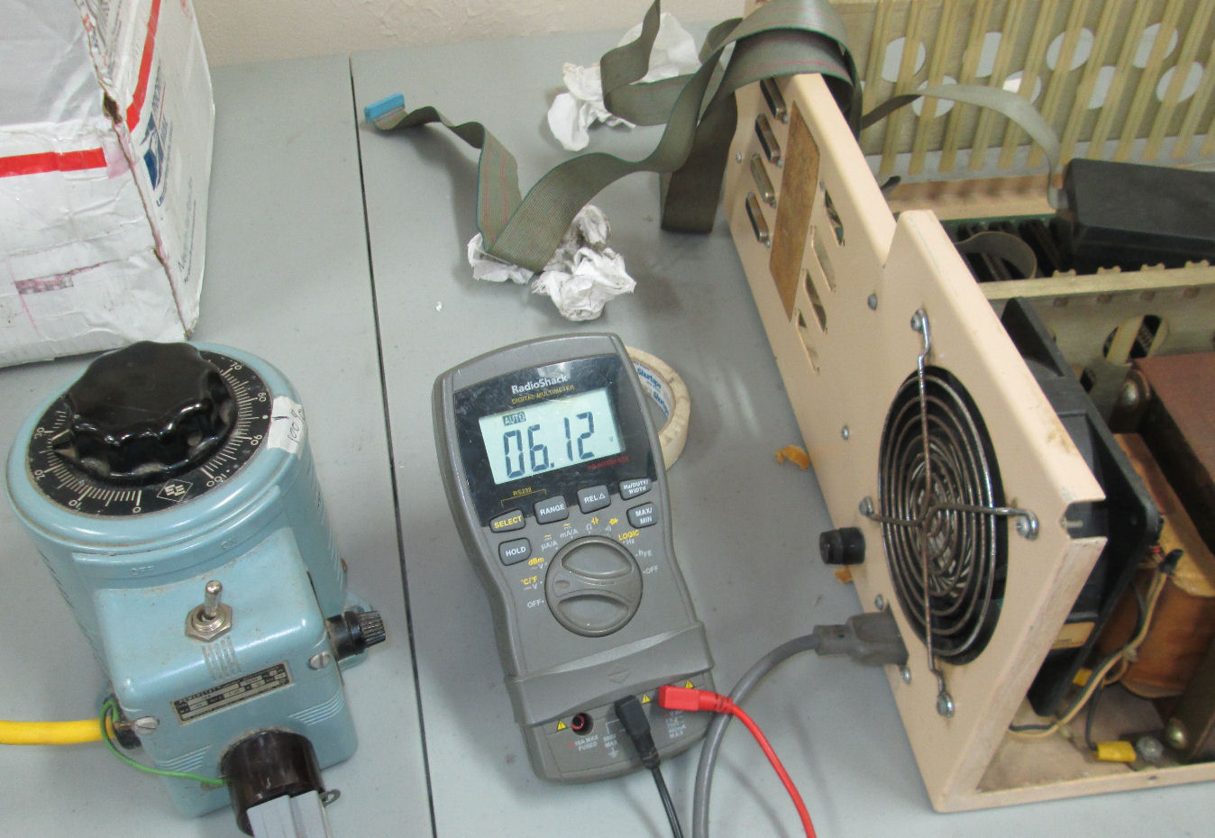
Summary: I reformed the large caps on the power supply and they worked satisfactorily that day. All boards but one were checked for power-line shorts and run up to DC bus voltages without blowing up. That sounds silly: but the failure mode for these 35-year-old boards is to literally ignite the tantalum capacitors in flames. I've seen it often. These pass that test, and their on-board voltage regulators appear to produce correct voltages, another failure mode.
On reforming the large power-supply caps. First I checked the full-wave diode blocks to be sure the diodes were not open or shorted; and ohmed the large caps to look for shorts. There was no regulators on the motherboard or supply. Fuses per DC line were OK, as was the AC line fuse. The empty cage was then powered by the Variac, to 10 volts or so, as I monitored for any immediate effects and measured the anemic DC output.
The point of "reforming" is to provide low current to the caps as their electrolyte re-establishes itself. Then the Variac voltage is raised to bring them up to full voltage rating over a period of tens of minutes in a gradual fashion. It's preferable to run them at near-rated voltage with sub-milliamp maximum current; then raise the current and voltage. But it's simpler to use the Variac to regulate current via rectified voltage.
On ohmic tests: All S-100 boards but one were checked for DC power-line shorts and run up to DC bus voltages without blowing up. That sounds silly: but the failure mode for these 35-year-old boards is to literally ignite the tantalum capacitors - which fail shorted - in flames. I've seen it often. These pass that test, and their on-board voltage regulators appear to produce correct voltages, another failure mode.
DC tests: Once the caps are likely reformed, then I added the cards one by one (after their ohms check as described above). For each card, I brought up DC voltage gradually, to look for too-low voltage outputs or inputs. There's likely some "reforming" of the small caps as well, in any event it allows me to monitor for hot components. The outputs of the regulators were monitors for proper DC voltage, once the inputs were within a few volts of rating. It's spooky to see no output voltage for a 5-volt regulator, until you give it about 3-3.5 volts input. No problems were found on any card tested.
In this photo the cards are in place and running at near-correct bus voltage. For the relatively low current (amps) of these cards, I ran the AC at maybe 75% AC voltage, for a 7-volt output on the +8V line. The -18V and +18V were little loaded and probably were near rated DC voltage. As long as the linear (T0-220) voltage regulators have a few volts drop, they will produce their rated voltage.
It's sometimes suggested to me, to run a "smoke test" - simply power up at full voltage and watch for damage and then fix it. Here's the problem. A shorted tantalum will run AMPS of current. It won't fail - the circuit board trace will fail and blow open. I'd rather not fix burned-out PC boards. My way is safer. And there's education from handling the boards, learning where the components are, verifying their DC regulators, etc.
I"ve not operated the system yet. I'll update accordingly.
Rich Fritzson contacted me July 2016, to offer me "... a S-100 bus computer along with an external 8" floppy disk drive and, I think, a Cherry keyboard". We made arrangements in August and he dropped it off late that month. He explained the system was signifigant to him, as it came from his academic advisor and colleage David Hays; they both produced good work in their field. As Rich and I talked, I noted the boot diskette had the STOIC operating environment. I recalled STOIC as one of many packages distributed with CP/M programs; Both Hays and Rich had worked with the STOIC language. Rich explained the FORTH roots of STOIC and we discussed our histories with FORTH. I asked Rich to send me notes about the prior owner.
Rich wrote the next day: "Again, I appreciate your taking the computer from me. I'm glad it's with someone who appreciates it. The list of cards in there is: [as given previously]"
"It was owned by David G. Hays when he was a professor of linguistics at SUNY Buffalo. He was the founder of the International Committee on Computational Linguistics and was also editor in chief of the American Journal of Computational Linguistics back then and used the computer to prepare content for the journal as well as his own personal research. He also ran a specialized IT business from his home using this computer. He died in 1995 [as noted by the NYT]. - Regards, Rich Fritzson"
Absent a manual, the following is all the documentation I have for the card.
My colleague and friend John Monahan at s100computers.com describes the origins of this system's video card. "James Babcock, who was a technician at SCION Corporation in the early 80's and worked on the Microangelo board and its successor the MA520 [said:] 'SCION was renamed from the company "Micro Diversions". Micro Diversions started business in 1978 and were located in Tysons Corner, VA. In 1981 the company moved to Reston, VA and was renamed SCION Corporation. As Micro Diversions, the company developed and marketed a product called "screen splitter". [Described as;] Screen Splitter: A text only video card whose visual memory was mapped to the S-100 memory address space. Supplied with a software library called "WordSmith", the screen could be 'split' into separate visual areas. Although visible as text only, this is a primitive design similar to the current Windows program. They also made a product called Frame Grabber -- the board could freeze a single frame from a video signal and digitize it. The board was a multi-layer S-100 format."
while "scion.com" is no longer operated by Scion, Web searching finds advertizements for the product. For instance in Byte. May 1978. p. 81, there's a "Micro Diversions, Inc. Advertisement for Screensplitter. Some of the text is below.
SCREENSPLITTER - A COMPLETE TV TEXT DISPLAY SYSTEM from Micro Diversions
SCREENSPLITTER is a self-contained TV text display system for your microcomputer. It comes on a single, high-quality S-100 compatible board, complete with its unique Window Package software module. With the Window Package, you can logically segment SCREENSPLITTER's huge 40 x 86 display of upper-lower case characters into up to 50 independent "windows" of various sizes. (You get the idea from our ad ! ) Each window has its own optional frame, cursor, figure- ground, and optional label, and each window scrolls and automatically formats its text independently of all the others."
POINTS OF INTEREST
Entire hardware/software system on a single, high-quality S-100 buss compatible board.
Drives a lOMHz or better TV monitor via standard 75 onm coaxial cable (supplied) .
4K static RAM -2114's- display buffer is memory-mapped into your CPU's address space for fast, convenient access if you ever need to bypass the Window Package software.
User-selectable wait state for operation with 4mhz CPU's.
IK onboard 2708 is jumper changeable to a 2K 2716 for user extensions to the Window Package.
Board presents one TTL load to host, yet drives up to 20 TTL loads via 74367 buffers.
Provisions for jumpering TV data, sync, blanking off board for external mixing.
The ad shows a collection of text windows to illustrate that functionality. Kit price was §295, assembled, $385.
volume 23 of CP/M User Group disks for a Z80 STOIC
Copyright © 2016 Herb Johnson
Follow this link to contact me @ my email address.