![[8f]](8f_march_three.jpg)
Most recent revision of this page June 1 2013. It's a work in progress.
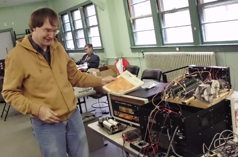
On May 18-19 2013, the MARCH vintage computer club sponsored a vintage computer repair event. Several people brought a substantial amount of vintage computers to clean, test, repair and for use. One of those systems was my PDP-8/F which was last cleaned and inspected at the previous MARCH fix-it event. Another was my recently purchased 8/e chassis and power supply. My colleage and PDP-8 expert David Gesswein, brought his 8/m plus an 8/f power supply, plus a bag o' tricks to test and repair my 8's. This document will describe some work and show photos of some systems during this event, which are of interest to me. Thanks to David Gesswein of pdp8online.com for his work and guidance, and for his review and correction of these notes. - Herb Johnson
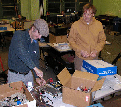
the photo on the left, shows the 8/e chassis in the back left; David's educompter 8/m on front left; and my 8/f on front right. Behind the computers
is a Omnibus serial card.
I discuss a number of these events on my Web site, as part of my general support for computer restoration. - Herb Johnson
![[8e]](8f_march_8echas.jpg)
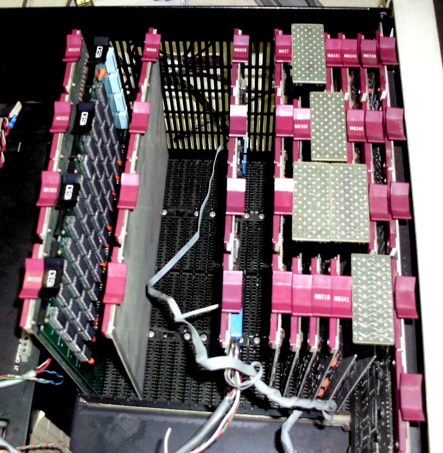
The 8/E chassis came with linear (non-switching) power supply and Omnibus backplane in a DEC chassis with key power switch. I also acquired a modified 8/E front panel PC board with some switches. The front panel was not tested, but David kindly sold me some switch caps for it. I took advantage of an air compressor on-site, to make sure all debris was blown out of the backplane. Visual inspection did not reveal any obvious corrosion among the card connectors. David noted the 5V 25A (!) fuseholder was replaced by a resettable circuit breaker, a common field upgrade.
Work on the chassis was relatively simple, as it was sold to me as previously powered. Therefore I did not expect the power supply to require either "conditioning" or substantial testing. David set up his resistor bank to load the voltages at the bus; we "fired up" the chassis and noted the voltages were within range. A switching supply should NEVER be powered without some load.
David informed me later about the front panel I obtained: "If you wish to verify [the model:] if the two 1/4" tabs power the LEDs then its an 8/E, since the 8/F & M doesn't have that power supply."
![[8f]](8f_march_resist1.jpg)
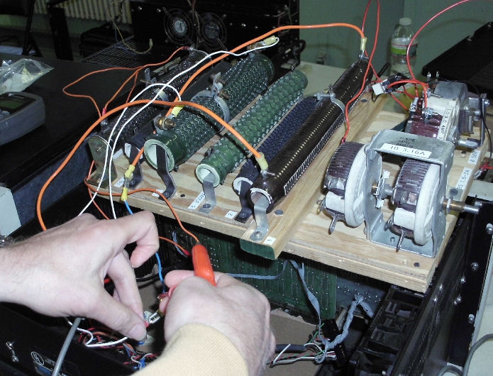
David providea a loading resistor bank of power resistors and rheostats (power potentiometers) to load down the power supplies in a controlled fashion. Ohm's law tells us the current draw based voltage applied. David confirmed the current ratings in his manual vs ratings on the back of the chassis.
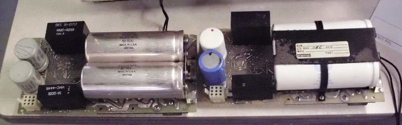
8/f power supply partly removed from rear of chassis To reform the caps they need to be removed from circuit. Of course this means pulling the power supply. It was not a problem, it was screwed in to a rear bay and cabled through Molex connectors. Once pulled, my 8/f supply on right, David's on left
The large caps on supply are easy to disconnect at the common connector, for reforming. The smaller caps on supply were removed individually for reforming. Herb (left) and David (right) are working on my power supply.
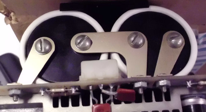
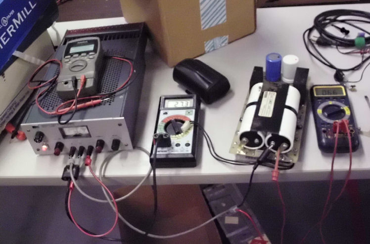
David's method to reform, is to use an HP lab-grade, current-limited power supply with voltage set to the cap's rated voltage; and current set to only a few mA. No damage can occur at that rating. Here's the reforming setup for large capacitor at 25 volts. The meter on the left monitors 27 volts; the meter on the right shows .066mA.
Initially the cap draws full current at zero voltage drop. As the leakage current falls, the voltage rises. Eventually the cap stabilizes at a reasonable leakage current - tens of microamps for these 10V to 25V capacitors. The process takes minutes, plus some time of several minutes of minimal current is allowed.
It's also important to correctly discharge the capacitors, AND the power supply! The challenge is to avoid either an unregulated surge into an empty cap, or a discharge out of a full capacitor. We lost a few DVM fuses in the process. But the four major capacitors appeared to reform successfully.
Afterwards, David explained the issue which led to the blown DVM fuses: "The fuse blowing was due to large capacitors fighting. The output of the [lab] supply I brought has some reasonably large capacitors on the output. They are after the power supply's current limit circuit. If either the supply is on and the capacitor you're testing is discharged; or the capacitor you're testing is charged and the supply is off; then you will get a spark and large current flow if you connect them together. This is how we blew the fuse. Its easy to be in a hurry or not pay enough attention and cause damage. Luckily it was just to a fuse."
"The proper procedure it to verify the [lab] supply output and capacitor are at
the same voltage before connecting them. A normal sequence is to turn the supply
off, connect, turn it on to reform, and turn down the supply to
discharge. You also need to know if your supply will safely sink the
current to discharge the capacitors. Some supplies can be damaged if they
try to sink too much current or won't sink it at all. If this is the case.
use a resistor to discharge the supply." - David Gesswein
![[8f]](8f_march_ser1a.jpg)
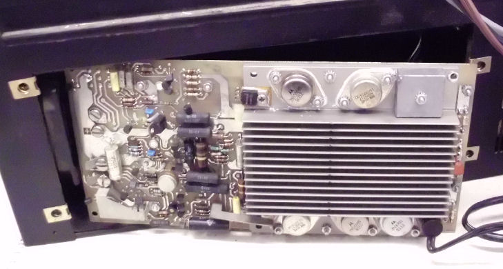
The next test was to restore the power supply to the chassis, disconect the power supply from the backplane but connect it to the resistor bank, and to bring up the supply to see if the voltages were acceptable. To disconnect the DC to the backplane, I had to remove the boards but keep the cabing intact.
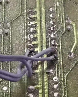
This is the original serial cable to the serial board There's a small flat cable as well, which was wired directly to points on the serial card, and to a front panel toggle switch. Part of the panel switch is wired here; and part panel switch is wired here. It apparently switches between two baud rates. David brought his own serial cable to connect to his laptop serial port. He has a terminal program, and an archive of test programs to download through the serial port.
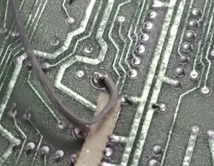
The 8/f also had DC cabling to some external device, unneeded so I eventually removed it. Of course
there are DC wires to the backplane from the DC connector. I had to remove these and connect them
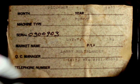
to the resistive loads instead. (The front panel was still in the backplane, screwed into the chassis.) With the boards removed
to get access to the DC wires, I exposed an internal chassis tag which shows the 8/f was
manufactured in December 1973 and has a serial number 03009XX.
![[8f]](8f_march_ptest3.jpg)
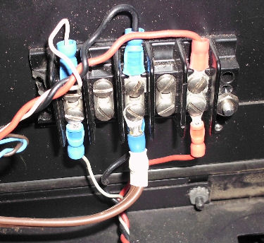
With access to the DC wires, I could patch the resistors into the 8/f supply for loading. With
David monitoring power we applied AC to the 8/f supply. With meters connected to
each DC supply, the 8/f supply under load showed reasonable voltages. 15.25 volts, 5.17 volts, and
-15.something volts were fine.
![[8f]](8f_march_ptest4.jpg)
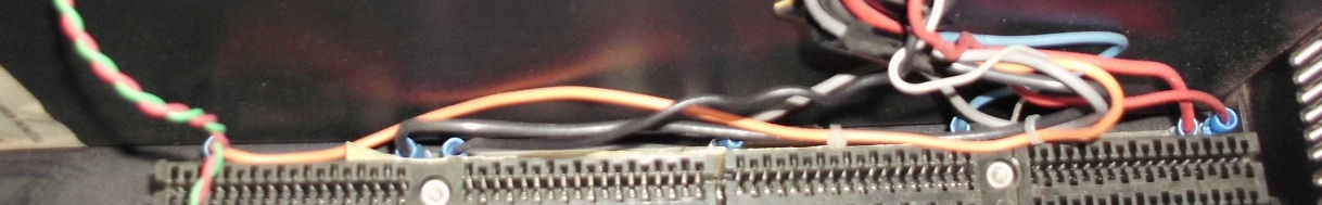
After restoring the DC wires back to the backplane, I put most of the boards back in chassis for power-up testing. From right to left, the front panel; the CPU board set; the serial card; a magnetic shield board; the DESI 16K RAM card; the bus terminator.
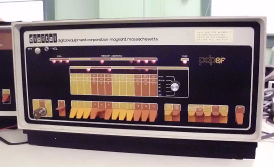
On first AC power-up with cards in place, the 8/f showed basic front-panel operations! A few toggled in checks by David, revealed the RAM card occuppied 4K banks 4 thru 7 (suggesting a previous 16K card supported the first four banks). He and I toggled in the RIM loader, which accepted the BIN loader, which accepted downloaded programs through the serial console port. We got a serial baud rate of 4800 baud, with the switch in the "HZL" (Hazeltine brand?) position. (We used David's serial cable but the switch was wired to the user-installed toggle on the front.) Here's the 8/f in running operation!
So with the serial loader operational, David could run a number of various diagnostics. All ran fine, one after another. So a more exhaustive test is to run 4K FOCAL, a BASIC-like programming language. This he could not run, for unclear reasons at first. One indication was that it did not run well in banks 4-7. So we powered down to look at the RAM card to see how it was addressed.
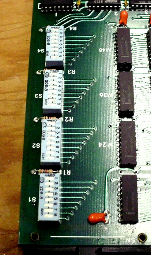
Turns out the RAM board switch settings are very simple. One toggle position of eight is set, for each bank 0-7 . The simple act of resetting them to 0 through 3, put the memory in the first four pages. With that change, FOCAL would load but not run. David loaded a serial of instruction diagnotics. One of them halted on a lack of interrupt flag set - that seemed to be the problem, as FOCAL needed an interrupt to operate.
With that issue identified, David swapped in his M8330 - the CPU board which supports the interrupt - and verified the diagnostic and Focal ran with it. Then we stopped since it was too late to start chip level testing. (Thanks to David for clearing this up.) A few days later, David sent me what's below on the subject, plus info on making a serial cable for myself.
- Herb Johnson
For your ION problem use this for the test program:
    1       0001          *1
    2 00001 7402          HLT
    3 00002 6001          ION
    4 00003 5002          JMP .-1
    5                     $
After executing the 6001 if you have the rotary switch set correctly the ION light should come on. This loops on it to make probing easier. If it halts then you got an interrupt. An interrupt will turn interrupts back off.
The 8/E maint manual volume one on page 3-151 discusses the interrupt enable logic. Find it at this link. And this Web page has a reasonably readable schematic for the M8330 board with the interrupt circuit.
Also we didn't use a scope to check power supply ripple. You may still wish to do that.
For the serial cable & board see these pages:
page #1
page #2
page #3
Looks like I bought TE Connectivity brand connectors to make the PDP-8 end of the serial cable: 6-87756-7 contacts and a 102387-9 housing. The housing has a polarizing bump which you don't want. It looks like I cut it off. It does have the proper width to fit the housing. I bought that back in 2009 so I don't remember why I bought with bump. The earlier one I bought didn't have the bump but also didn't have the extra plastic at the end so it would go in one pin off. It looks like they do have ones that look right such as 1-104482-8 but check width. The 3-87651-5 looks the style that I bought that is too narrow.
- David
Other information on David's site about capacitor reforming includes:
notes on reforming caps for a straight-8
- herb
Copyright © 2013 Herb Johnson