In mid-June 2010 I recieved a SWTPc 6800 system: see this Web page of my first views of that system. ON this page I describe my cleanup and testing of it. last edit July 13 2010 (C) Herb Johnson
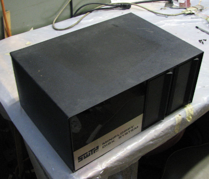
SWTP MF-68 dual drive cabinet with two Wangco model 82 5.25-inch single-sided drives
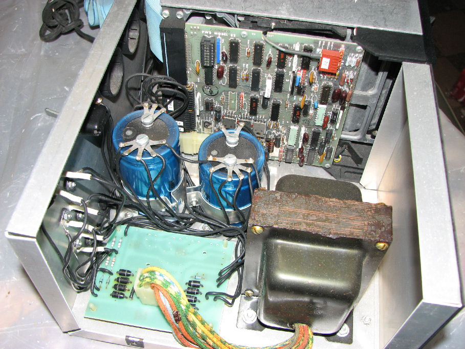
interior of drives case
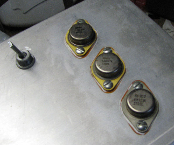
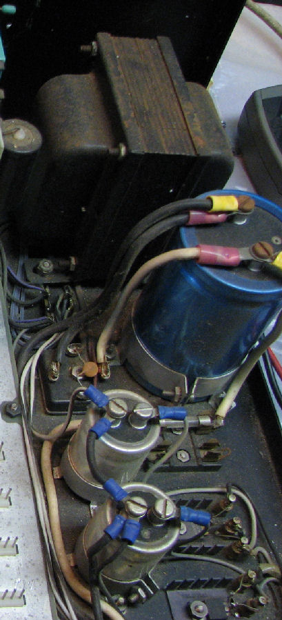
regulators on back and AC switch
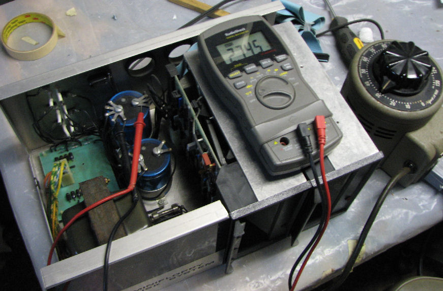
power up under variac
The drives looked in good shape. I ohmed out the +5 and +12 supplies to confirm there were no shorts. Then I attached the Variac and applies low voltage AC power, to confirm the regulators were operating and not shorted. Also this provides the large electrolytic capacitors a chance to "reform" after sitting idle for years. (That may not be necessary for modern large caps but it does no harm.) I ramped up power over tens of minutes. It was a relief to see the output of the voltage regulators (at the floppy drive) stablize at about 5V and 12V respectively, at around 100VAC input. On the way "up", the drive motors started rotating; that ended once the 5V power got high enough to "set" the logic to not run the motors. I've seen that happen before.
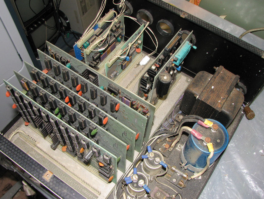
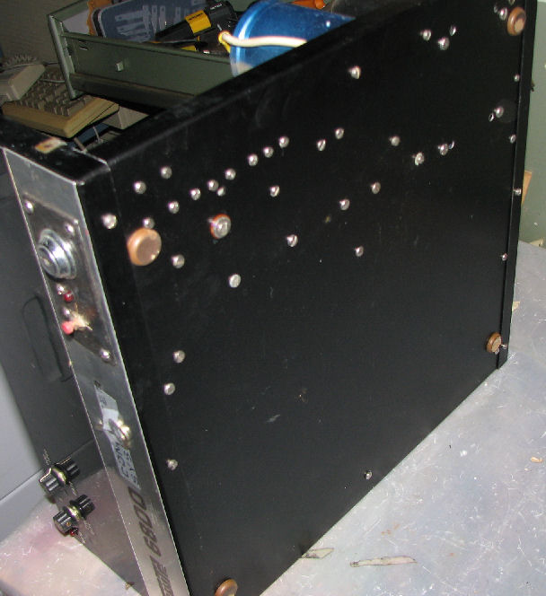
SWTP 6800 system cabinet before cleanup, from side.
SWTP 6800 system cabinet before cleanup, from other side.
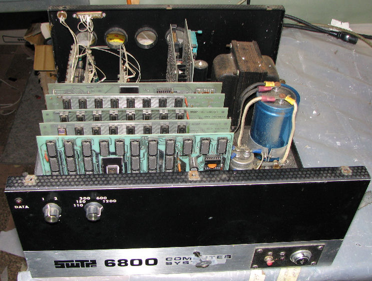
SWTP 6800 system cabinet before cleanup, from front.
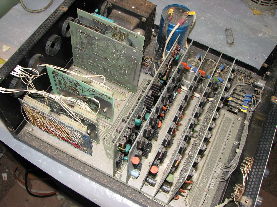
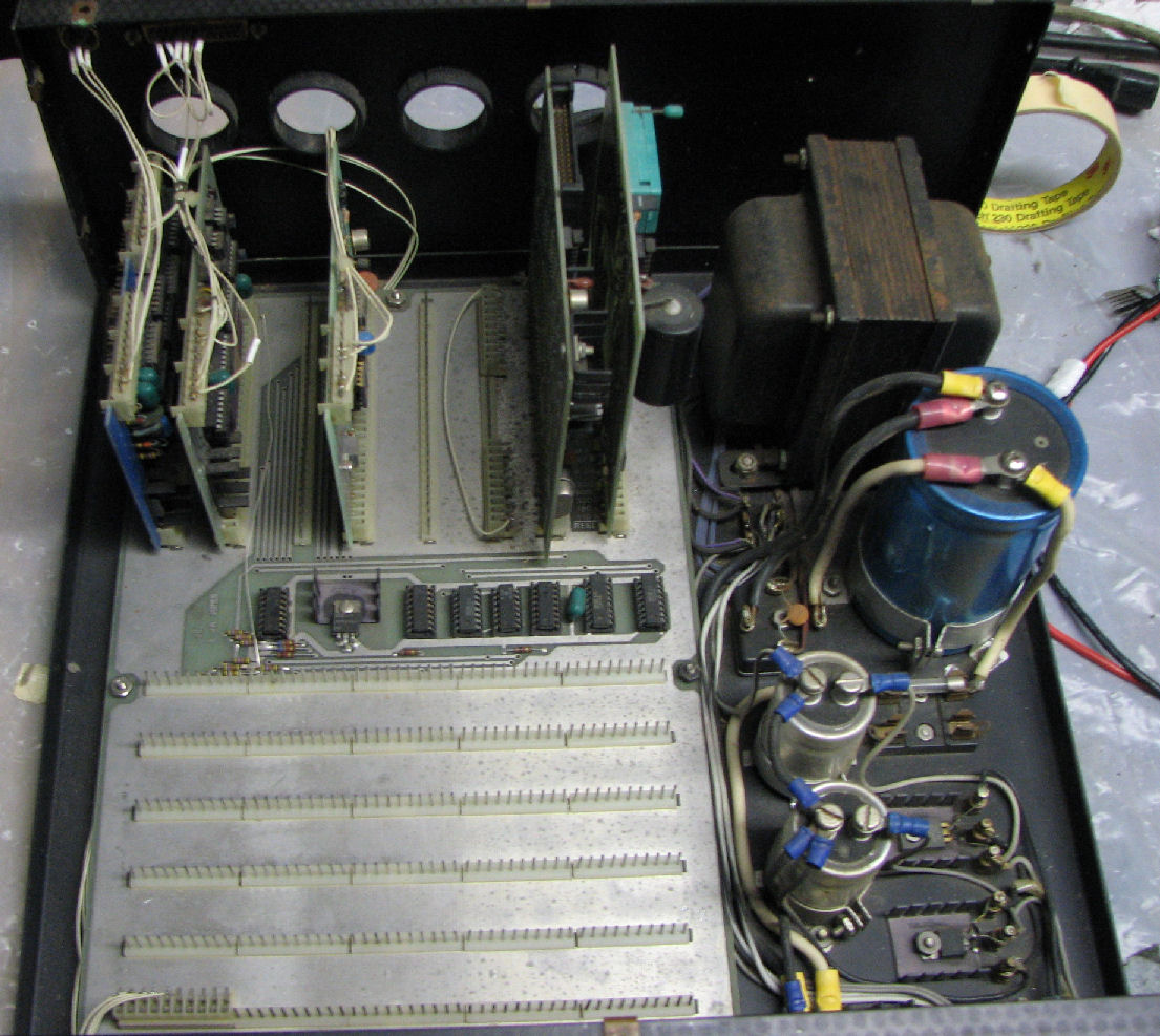
SWTP 6800 system , SS-50 cards removed and some dusting.
SWTP 6800 system , SS-50 cards removed and dusting completed.
SWTP 6800 system bottom.
Remove and ohm-out SS-50 cards:
slot 0: set baud rate wired to front panel switch
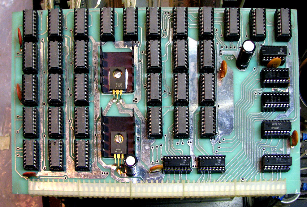
slot 1: MP-M 8K RAM with 21L02-3 RAM chips
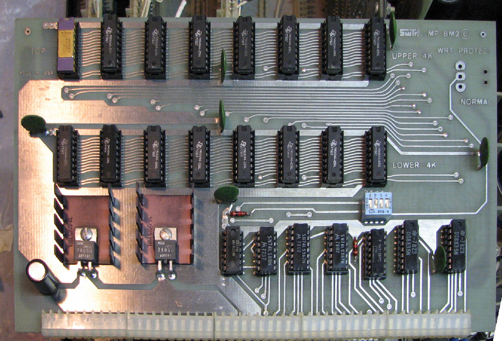
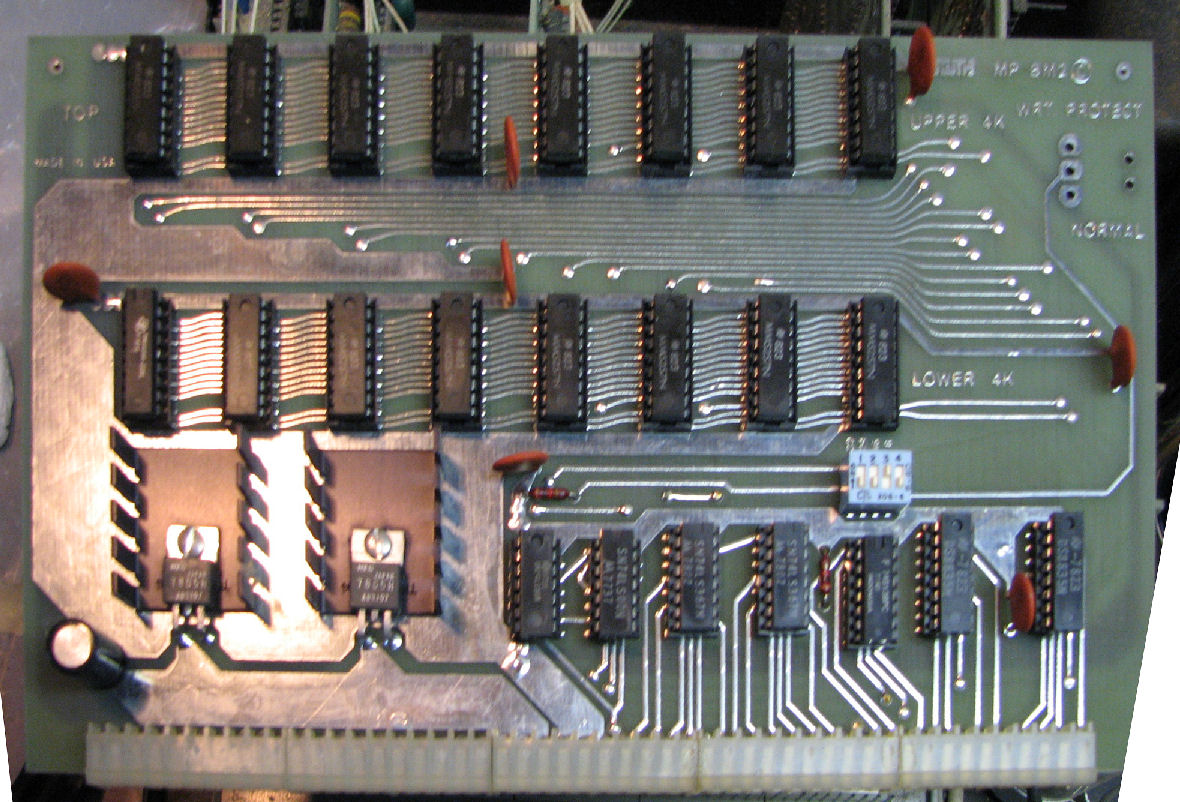
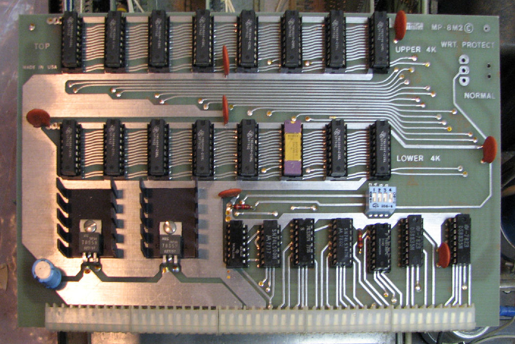
slot 2: MP-8M2 8K RAM (board 1) w/ TMS4040-25 RAM chips from mid 1978
slot 3: MP-8M2 8K RAM (board 2) w/ MM5257N RAM chips from mid-1978
slot 4: MP-8M2 8K RAM (board 3) w/ TMS4044-25 chips from mid-1979
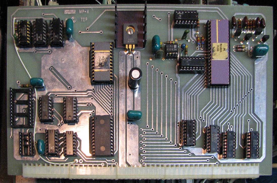
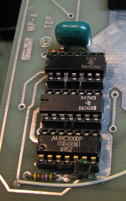
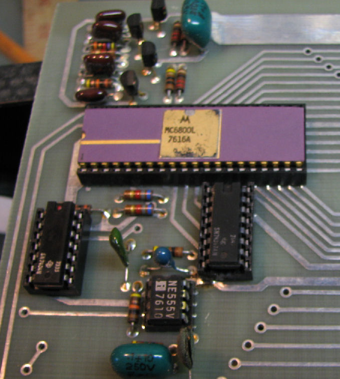
slot 5: MP-A 6800 CPU
MP-A 6800 CPU board has some pins bent out as a "mod".
closeup of 6800 CPU
with SS-30 I/O cards
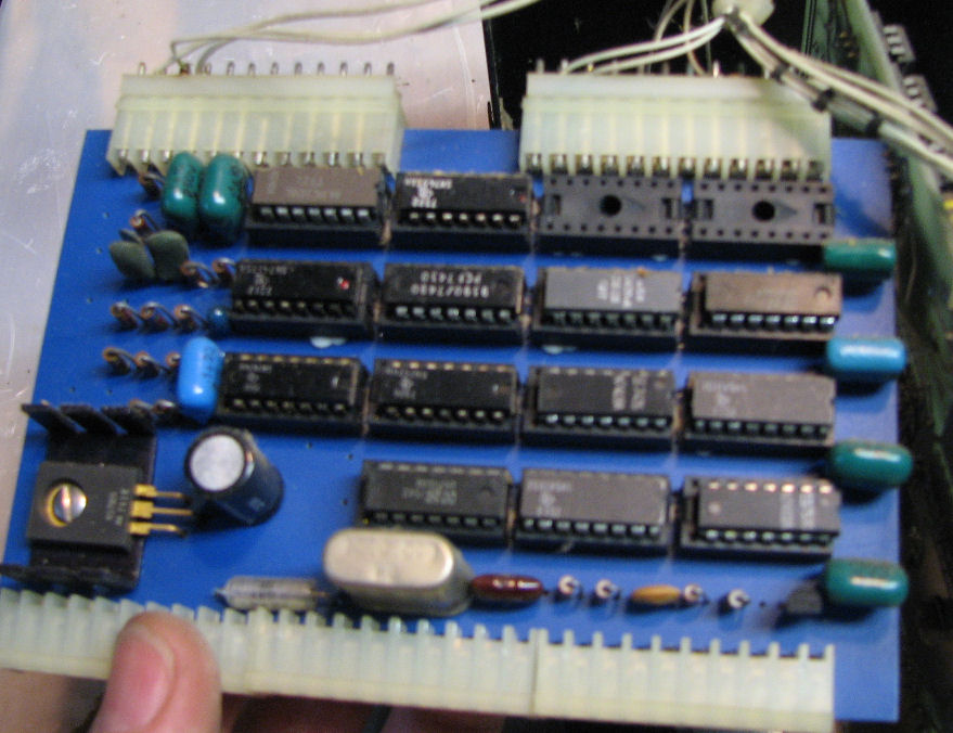
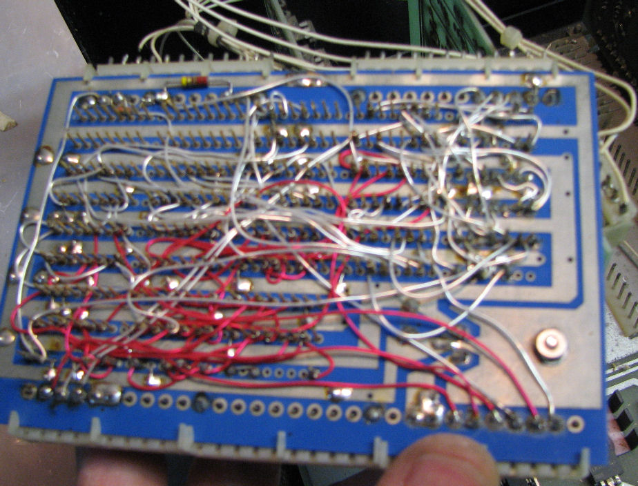
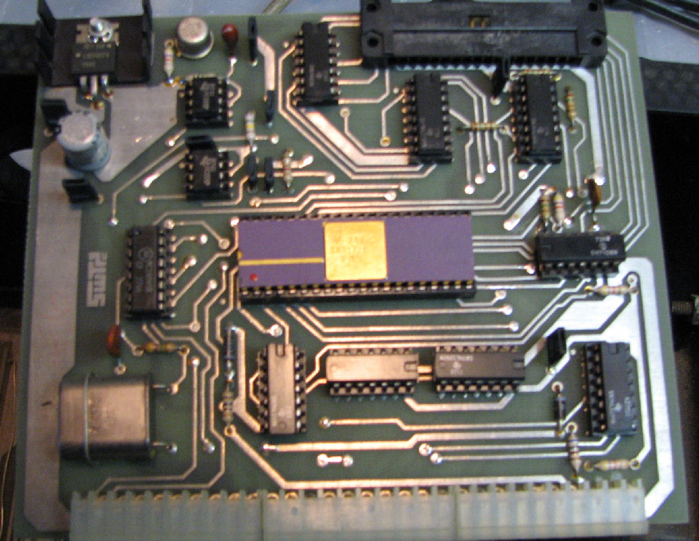
slot 0: wirewrap KC cassette card (see notes below) and back of wirewrap card
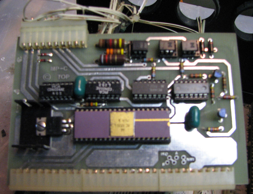
slot 1: MP-C serial w/6820 wired to front panel baud switch & rear DB-25
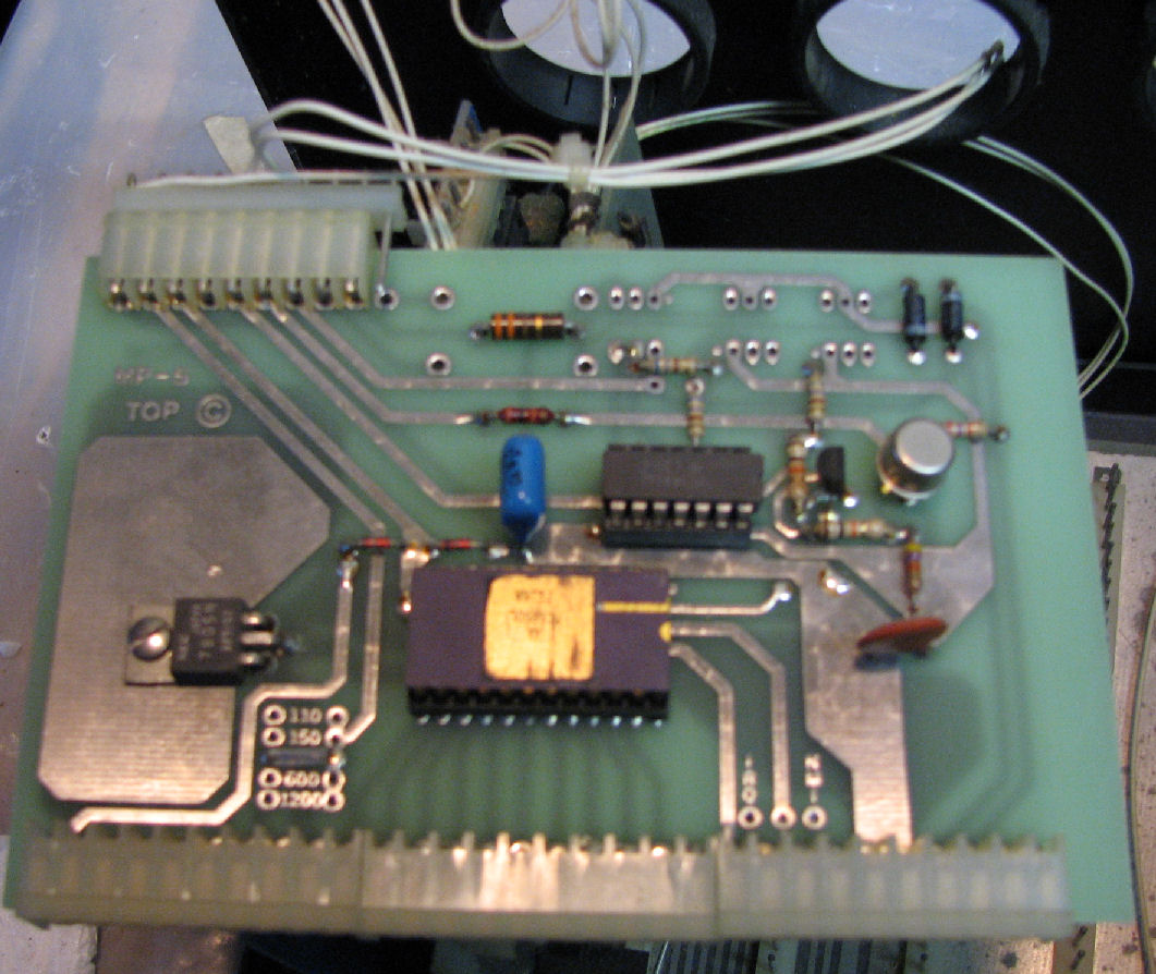
slot 3: MP-S serial w/6850 set at 300 baud and wired to loose DB-25 on back
slot 5: jumper from /RESET to UP3
slot 6: DC-2 1771 FDC controller
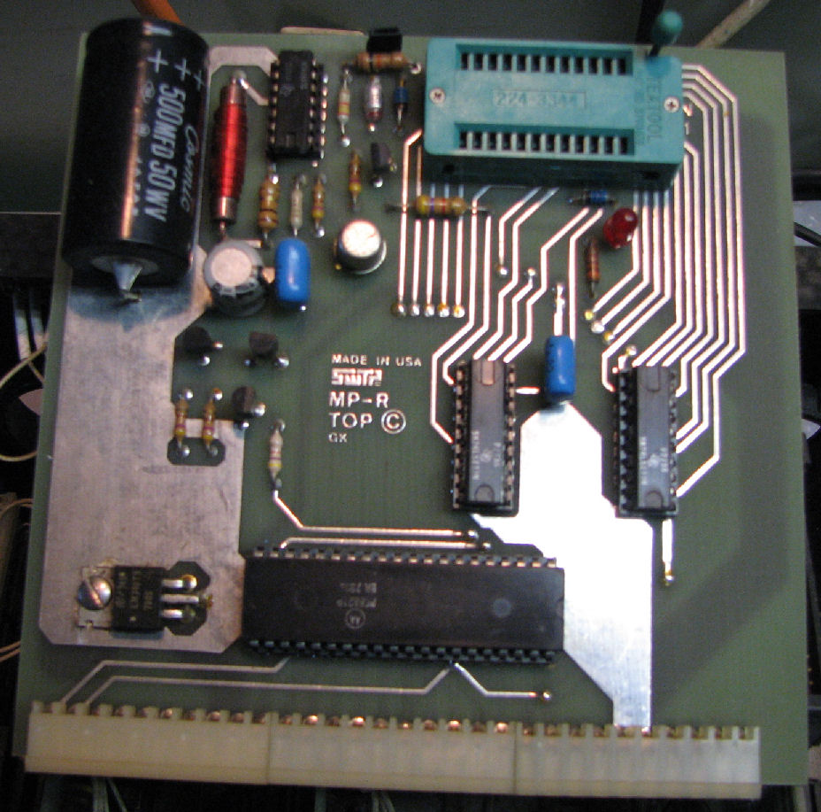
slot 7: MP-R EPROM programmer 2716 5V
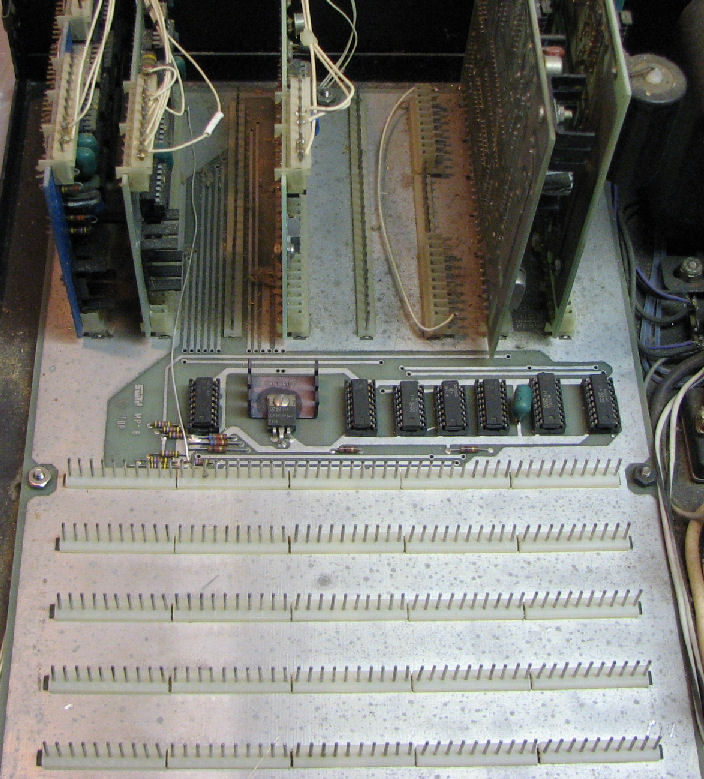
MP-B motherboard
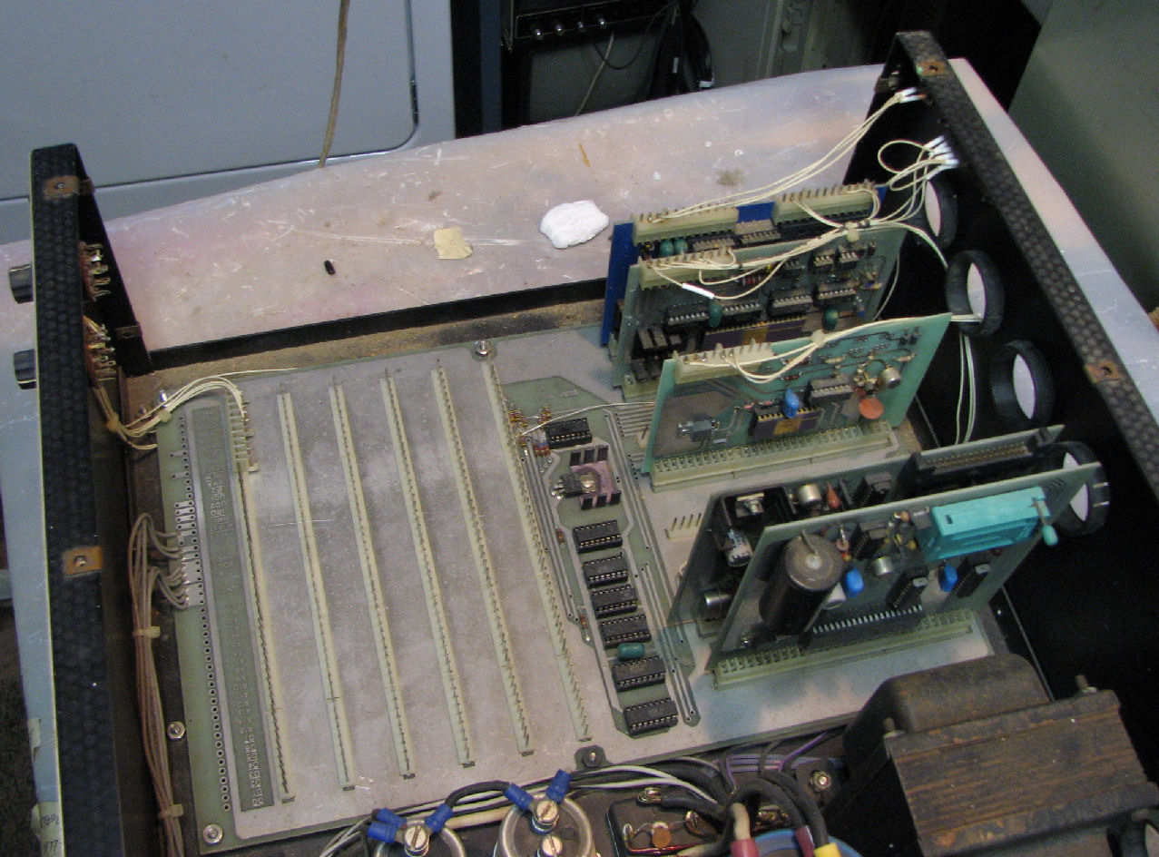
motherboard with SS-50 cards removed
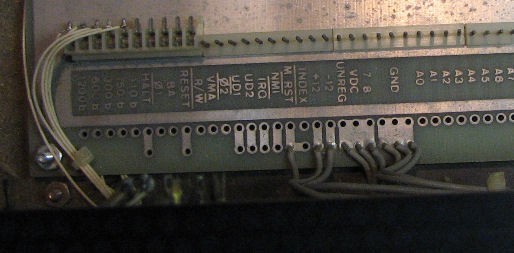
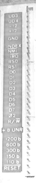
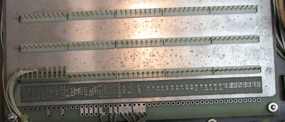
motherboard 30-pin I/O bus in back
motherboard 50-pin bus at front. These slots share all memory addresses.
MP-P power supply
view of most of power supply
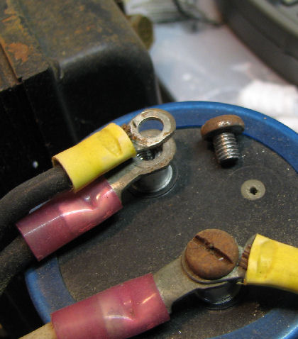
replaced these rusty screws
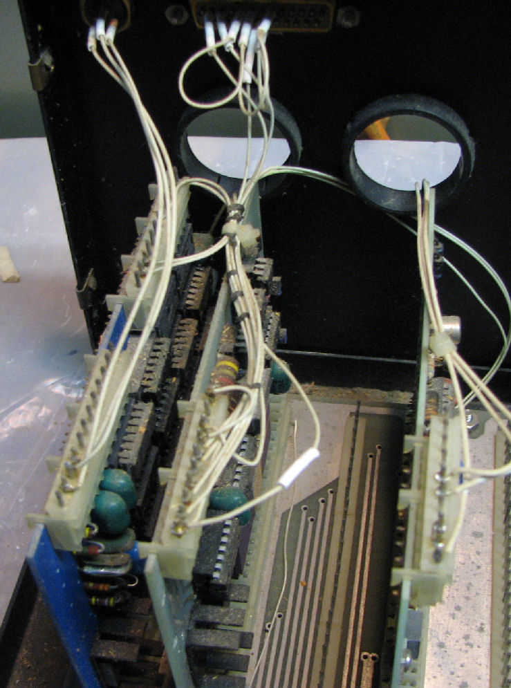
Wiring of serial and wire-wrap cards to connectors. The connector to the top center is a DB-25 with several wires, connected to the MP-C in slot 1. The connector on the top left corner is a circular connector, probably for the cassette interface. WIres going out the rear hole, are to a "loose" DB-25 which is associated with the MP-S card in slot 3.
Each 30-pin I/O slot is numbered and represents specific memory locations from 8000H to 801FH, four locations per slot. The ROM monitor requires slot 1 to have a MP-C card for serial I/O to a terminal device.
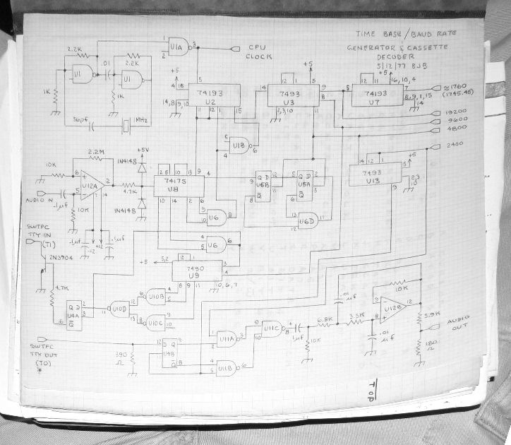
The original owner of the system, Bruce J. Black, says: "The wire wrap [in the computer] is the Kansas City cassette interface. There is a schematic for it on a hand drawn sheet of sketch vellum." The document is dated May 1977. More comments from Bruce are on this Web page. - Herb
June 10-12: With processor and memory cards removed, I put a Variac on the system and brought up AC power to 10V. Checking the large caps and the two voltage regulators on the chassis, I saw no obvious shorts. I brought up AC voltage to 30V and checked the regulators again. I was not happy with the response at the output of the +12V regulator, it seemed low. So I took my time to check each I/O card for shorts or problems with the 12V line. Seeing none, I thought the low resistance at the output of the regulator was too low. So as a precaution, I replaced the regulator with a similar one.
However, the +12V replacement performed about the same way. So with caution I raised the AC voltage up to about 60V. Sure enough, once the input to the regulator approached about 9V, the output began to rise. At 80V AC, the output was about 10V; at 80V to 100V, the output was just over 12V. Meanwhile the -12V regulator worked OK, and the 5V regulator on the motherboard worked OK.
Next, I restored each of the four memory boards and the CPU boards to the motherboard, one at a time. I powered up to 100V AC, and monitored the power supplies. All behaved appropriately. I also monitored the 5V regulators on each card; I know these to fail over the years. But all performed adequately, producing 5V to 5.4V. So I restored ALL the boards to the motherboard and powered up. No "smoke", no hot regulators.
My next step will be to check the operation of the SWTPCbud ROM monitor with oscilloscope and terminal. Chances are the system will not come up; it does not take much of a failure for that. Also I need to confirm the configuration of the system and what to expect, based on SWTPC documentation and the owner's docs. - Herb Johnson
Copyright © 2010 Herb Johnson