S-100 and IEEE-696 Bus
This document last updated July 29 2026(c) Copyright 2026 Herb Johnson
To return to my S-100 Web page click here.
S-100 History and Bus lines: Altair/IMSAI, IEEE-696 & others.
Note: the images of the IMSAI CPU card and SD Systems backplane may be freely used by anyone. I request they be identified as from Herb Johnson and a link made to this page. Additional photos are available on those terms are available at this Web page. - Herb Johnson
Introduction
I think it is fair to say there are THREE major versions of the S-100 bus. There was the original "Altair bus" of the MITS Altair 8800, the IMSAI 8080, and cards immediately compatible with those two systems. Then there was the "S-100 bus" which has a number of changed bus signals but which are largely cross-compatible with modest hardware changes. Finally, the "IEEE-696" which generally expands and speeds up the S-100 bus. However, in general discussion all three "versions" are collectively called "the S-100 bus".
This Web document walks through the three bus variations and some history of their development. See this linked Web page for a discussion of the development history of the S-100 bus from the Altair to IEEE-696 systems of the 1980's and later.My S-100 home page links to many documents about S-100 and lists over 140 S-100 brand companies.
If you are not familiar with "a computer bus", or think that computer busses were
always around; well think again. Here's a history of microcomputer
busses and why they arose, and why some computers didn't have them, or couldn't have them. - Herb Johnson
Three "versions" of the S-100 bus
Altair / IMSAI bus
![[IMSAI 8080 CPU]](l_s100_imsai_cpu.jpg) The MITS Altair 8800 of course was the introduction of the "Altair bus", first published in the January 1975 issue of Popular Electronics. IMS Associates, Inc. replicated that bus in its product, the IMSAI 8080 of late 1975. (The photo on the left is the IMSAI 8080 CPU card.) These two systems are the iconic representations of "S-100". On the IMSAI bus, several of the MITS bus signals were replaced or ignored, but the core set remained: two 8-bit unidirectional data lines, 16 address lines, the 8080 status and control signals, some front-panel control lines,
and power (unregulated positive and negative 8 volts, unregulated positive
and negative 16 volts). Power was regulated on each S-100 card with
individual voltage regulators: +8 became +5 for logic for instance.
In this document we refer to the Altair/IMSAI bus as the first version of the S-100 bus, as listed below. Also examine this linked document for a list of IMSAI and Altair signals.
The MITS Altair 8800 of course was the introduction of the "Altair bus", first published in the January 1975 issue of Popular Electronics. IMS Associates, Inc. replicated that bus in its product, the IMSAI 8080 of late 1975. (The photo on the left is the IMSAI 8080 CPU card.) These two systems are the iconic representations of "S-100". On the IMSAI bus, several of the MITS bus signals were replaced or ignored, but the core set remained: two 8-bit unidirectional data lines, 16 address lines, the 8080 status and control signals, some front-panel control lines,
and power (unregulated positive and negative 8 volts, unregulated positive
and negative 16 volts). Power was regulated on each S-100 card with
individual voltage regulators: +8 became +5 for logic for instance.
In this document we refer to the Altair/IMSAI bus as the first version of the S-100 bus, as listed below. Also examine this linked document for a list of IMSAI and Altair signals.
"S-100 bus"
Many people bought an IMSAI 8080 or MITS Altair 8800, and began to manufacture
their own "Altair plug-in" boards. They used slight variations of the Altair or IMSAI bus;
even MITS varied their bus in later Altair models. With a suggestion from Roger Mellon of Cromemco, they referred to their bus as "the S-100 bus", based loosely on their "standard" use of the 100 pin bus: check this Web document for some details. Most variations of use, amounted to different signals to accomodate refresh or memory timing. Some front panel signals (such as memory write protect) did not persist as systems were developed without elaborate front panels.
Also, there was a loose standard for managing banked memory (16 bit address = 64Kbytes memory) via I/O ports, but there were other memory-managing schemes as well.
![[SD Systems S-100 backplane]](l_s100_sds_plane.jpg) Many 8-bit processors were adapted to the S-100 bus in this period of the later 1970's,
but most systems used the 8080, Z80 or 8085, and later the Intel 8088 or 8086. All continued to use
16 address lines and 8 unit-directional data lines. We call this later bus
"the S-100 bus" and this second version is listed below, followed by other varients. The photo on the left is a typical S-100 terminated backplane or "motherboard". In addition to the 100-pin connectors, there is a circuit to provide a voltage and impedance (resistance) load for each bus signal line.
Many 8-bit processors were adapted to the S-100 bus in this period of the later 1970's,
but most systems used the 8080, Z80 or 8085, and later the Intel 8088 or 8086. All continued to use
16 address lines and 8 unit-directional data lines. We call this later bus
"the S-100 bus" and this second version is listed below, followed by other varients. The photo on the left is a typical S-100 terminated backplane or "motherboard". In addition to the 100-pin connectors, there is a circuit to provide a voltage and impedance (resistance) load for each bus signal line.
During the late 1970's, many companies (and individuals) produced "adapter" products to add S-100 cards to their computers, which
were not otherwise S-100 compatible. The "KIMSAI" was a small S-100 bus board for the 6502-based KIM, for example.
The Digital Group incorporated some S-100 slots into their brand-specific backplanes.
S-100 I/O cards were an available way for those computers to expand, particularly to add a (S-100) floppy controller.
The 1979 book "The S-100 Bus and other Micro Buses" not only describes these other computer busses, it also describes
adapter designs for those busses to S-100 I/O boards. The book also covers variations to the 1970's "S-100 bus"
signaling as used by "not 8080-based systems", presumably use by adapters.
IEEE-696
In mid 1978, one S-100 variation was initially suggested for an IEEE standard, by George Morrow and Howard Fullmer at the West Coast Computer Faire. That proposal was for a 16-bit address bus and two 8-bit unidirectional data busses. [George Morrow passed away in 2003.
Bill Godbout passed away tragically in the 2018 Camp Fire in California.]
Subsequently, Compupro (Bill Godbout) and Morrow Micro-Stuff (George Morrow)
and others developed a faster and expanded S-100 bus. It provided bus speeds to 10 MHz,
24 address lines and an option for EITHER 2-8 bit one-directional data paths or one
16-bit bidirectional data path. Other features included master/slave
arbitration and bus mastering arbitration; these exchanged control of the bus from one CPU board to another, or temporary control for DMA (direct memory) transfers.
This expanded bus was developed and discussed through an IEEE-696 standards committee. People on the committee included Godbout, Morrow, William Stark (Ithaca Intersystems), Sol Libes, and many more. [See published copies of the standard for complete lists.] Many of these people worked at S-100 companies who produced cards following the developing standard.
A preliminary IEE-696 specification was published in the July 1979 IEEE Computer magazine. We call this the third version of the S-100 bus. Those signals are listed below with the Altair bus signals. Over time, these and other companies produced CPU cards with Motorola or Intel 16 or 32-bit processors, using 8 or 16-bit memory cards, for single or multiprocessor systems. They out-performed the IBM-PC's of the era, up until roughly the late 1980's. We document a number of these later busses in the bus signal lists below.
1990's and beyond
While a de-facto standard since the late 1970's, the IEEE 696 committee only approved it in 1983. Unfortunately this was around the time new S-100 bus designs were challenged by the IBM PC products. On another Web page I discuss the impact
of the 1981 IBM PC on S-100, and how S-100 led the way for the IBM PC. But S-100 cards were still developed and sold in through the 1980's, and beyond.
The IEEE withdrew their standard in June 1994. In effect they concluded that manufacturers were no longer designing IEEE-696 products.
By this time, costs of PC board design and offshore production were low enough that groups of techies were starting to produce their own
designs. In later years, other individuals would reproduce earlier boards or design to S-100 standards.
These are specific notes about features particular to S-100 microcomputers and about their repair and maintenance as a result of these features and of forty-fifty years of time or use. For more generic 1970's-clall repair notes, check this linked page.
Pin locations: The front of an S-100 card is the "component side". With the connector down (as if to insert), the leftmost pin is ONE, the rightmost is FIFTY. If you reverse the card to the back (generally no components), the leftmost pin is ONE HUNDRED, the rightmost is FIFTY-ONE. So pin 1 and 51 are atop each other, and in fact are connected to each other - they provide +8 volts (+5 if the bus has regulated power). Also pin 100 and 50 are atop and connected to each other, and provide GROUND.
Regulated power backplane: Compupro and other S-100 card manufacturers produced backplanes with regulated power voltages; +5, +12, -12 volts. Cards used with this backplane, either had their voltage regulators removed, or shorted out (input to output for 3-terminal regulators). Generally such cards were clearly marked, but user-modified cards of course are not. Cards without regulators, if plugged into a non-regulated bus of, will almost CERTAINLY BE DAMAGED. Unregulated "+8 volt" supplies with no cards, can exceed 10 volts! Unregulated "+18V" and "-18V" can exceed 22 volts.
S-100 backplane connector spacing of pins: By MITS Altair, S-100 and IEEE-696 standards and practices, the 100 edge-connector pins are .125 inches apart, or a "pitch" of 8 pins per inch. But the spacing between the two rows of pins,
on the backplane and the board connectors, was not standardized in the IEEE-696 specification. As it turns out, the MITS Altair and some early Altair-bus computers used a narrow .140 inches between the rows. But most subsequent
S-100 and IEEE-696 systems used .250 inches between the rows. Check your backplane and replacement
connectors to confirm they have the same row width. For more history and a list of measurements, read this linked document.
S-100 backplane, spacing between connectors: The S-100 boards are of course, inserted into backplane connectors
and slide into board guides in the chassis. For most S-100 and IEEE-696 systems, these connectors are 3/4" apart BUT ..
But I haven't checked the earliest "Altair bus" systems: the MITS Altair, the Polymorphic, the Processor Tech SOL, Northstar
Horizon ... better measure before replacing that motherboard! ;)
S-100 signal placement: Some people at the time, and still today, complain about the layout of signals on the S-100 bus. However, other busses of the period also had signals distributed in a "non-sequential" order on their "bus". Look at this document of Intel's bus for their Intellec development systems of the early 1970's. The Intellec preceeded Intel's Multibus. But Intel's Multibus has pretty orderly signals for address and data. One suggested reason for non-sequential ordering is to isolate more "active" lines between less-active lines to avoid crosstalk. Example: address lines A0, A1, etc are more active than A14, A15. A pragmatic reason is: easier routing from chips to edge connector. And consider this: the original MITS design was, after all, the first and so was arbitrary.
Not all "S-100" cards and systems are cross compatible. Alpha Micro produced a 16-bit computer which used S-100 connectors but a taller PC board, for their AM-100 product line. On this page we compare the AM-100 lines to the Altair/IMSAI lines. Beyond that, the 100-pin connector was an industrial product, and used by manufacturers to produce
cards with no intention of S-100 signal compatibility. So look carefully at unfamiliar brands of "S-100" cards, and confirm
they at least have grounds and DC voltages on S-100 compatible pins!
Altair/IMSAI bus pin 20 and 70The MITS Altair front panel used bus signals pin 20 and 70, to disable writes to parts of
memory. Pin 20 was "memory unprotect" and pin 70 was "memory protect". That function was not replicated in the IMSAI, and in
subsequent S-100 and then IEEE-696 systems. In fact, those pins were *grounded*. That creates an odd problem: some old S-100
boards when put into other S-100 systems will disable those systems. Read this linked Web page for details on S-100 pins 20 and 70.
Altair/IMSAI bus pin 53On the Altair/IMSAI bus, pin 53 is the /SSW DSBL (Sense Switch Disable) signal. On the IMSAI front panel CP-A, this signal allows the front-panel to read address switches for an IN FFH operation from the front-panel. It is read (active low) by the IMSAI CPU board to disable reading 8080 data from the data bus (so the Front Panel can provide data). The MITS Altair boards are likewise. The IEEE-696 doesn't support these functions, so it grounds that signal on various IEEE-696 boards.
For more information about signals 20, 70, and 53 (among other signals), read the manuals and schematics for the IMSAI or MITS CPU and front-panel boards, versus documents for the IEEE-696 of interest.
one-shots, monostables and S-100 front panels Early S-100 front panels, and some other S-100 cards,
used an IC called a "monostable multivibrator", commonly called "one-shots". They produce a single pulse
based on a logic triggering signal. The common TTL monostable ICs were 74121, 74123. In particular they were used in front-panels to manually single-step the 8080 (or Z80) processor. Here's some notes about the MITS 8800 front panel one-shots. These one-shots have a history of soft-failing as their
timing resistor and capacitor values break down, or the IC internal trigger breaks down. This situation applies
to the IMSAI front panel, and to some timing circuits on many other early S-100 cards.
S-100 buss connector "ears" get damaged: In Feb 2021, I had a conversation with a former MITS/Pertec system service tech. They informed me about some interesting problems with the MITS Pertec S-100 backplane and connectors. Apparently the connectors became intermittant due to stresses produced by screwing the "ears" of the connector into the chassis and backplane board.
The "ears", are the screw-holes at either end of some brands of S-100 connectors. With permission I gathered up that conversation. Here's the notes from that MITS Pertec service tech. PS: If your S-100 card's edge connector has sharp corners, you *may* want to round them
off with a file. That reduces the insertion force that leads to breaking the bus connector's "ears". - Herb
Removing S-100 connectors from backplane:Over the decades, backplane connectors break or rust. Individual pins
might be replacable. But desoldering all 100 pins to remove a whole connector is too risky. Here's what Lee Hart advised
in Sept 2022: "If the part is bad anyway, sacrifice the part to save the PCB. Break or cut up the plastic body of the connector [if necessary, but remove and] unsolder each pin individually. Tedious, but much safer for the PCB."
"Start at one end [and look carefully]. See if you can break/cut/grind away enough of the plastic to see how [that] pin is retained in the body. If there is just a little barb that holds the pin in the body, see if you can depress it with a jeweler's screwdriver. Then grab it with a little wire hook. While you heat the solder on the back, you can pull each pin out individually. I've used this technique to replace connectors on S-100 boards, which are even worse than
{these 86 pin connectors]!" - Lee Hart
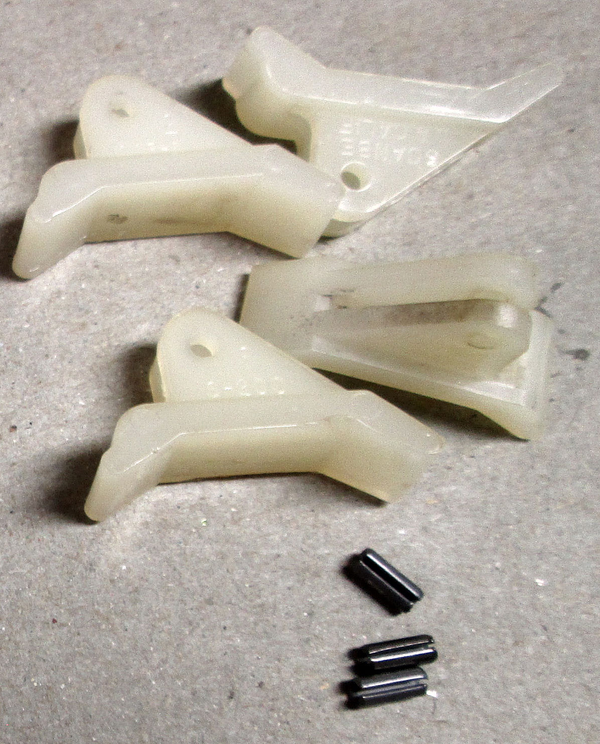
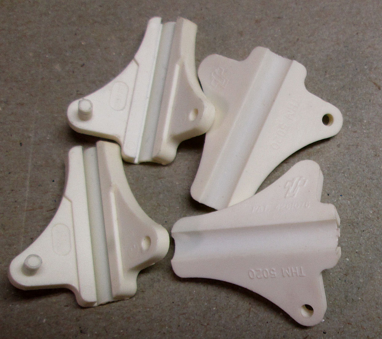
S-100 card ejectors, board thickness: While working on another restoration, I paid attention to S-100 card ejectors.
That's the plastic (often Nylon) tabs at either corner of PC boards to lever or "eject" cards from the card cage. There were
some standards of sort for these things: .093 inch holes, .25 inches from either edge to mount, board thickness .065 to .071 inch, about 1/16th.
I have some ejectors around. Here's one nylon ejector Scanbe S-200. The metal pins are called "roll pins", these are 3/16" long. By eyeball, these S-200's look a lot like
this Bivar CP-06 NT model. Here's a cheaper plastic fold-up ejectors, Thermalloy 5020, with plastic pins - these get brittle with age. Ejectors vary in features but these two are just over an inch long. Lots of boards in the 1970's and 80's in card-cages had these. -- Herb
IMSAI front panel and buss connectors Mechanical features specific to the IMSAI front panel and IMSAI backplane, may correspond to other front-panel S-100 systems. The Ithaca Intersystems DPS-1 has
a front panel board. Also there's IMSAI compatible brands of front-panels and backplanes. The MITS Altair 8800 series is different, they have cables from the front panel to the MITS backplane or some logic controller S-100 card. (Some people upgrade their Altair by
wiring the front panel to a simple S-100 connector board, and not directly to the Altair backplane as original.)
The IMSAI front panel is connected to the IMSAI bus through a backplane connector,
just like any other S-100 card. But mechanically the front-panel backplane connector is
different in important ways. First, the connector's top edge must be of exact height so the front panel PC board's screw holes align with the IMSAI chassis. Practically, the connector height must be .6 inches or less from the backplane PC board. One IMSAI backplane I have, uses a TI brand (H3221 50 337A) connector of that height. Other connectors on that backplane are .625 (5/8) inches tall (CPH 8100-100ST for instance). Second, the front-panel buss connector is spaced further from the other buss connector. I'll measure that later.
References:
"The S-100 Bus Handbook" by Dave Bursky. Hayden Press, 1980
various IMSAI and Altair hardware manuals
IEEE Standard 696-1983, notes in the "Forward"
May 1978 and July 1979 articles in IEEE Computer magazine, "Standard Specifications for S-100 Bus Interface Devices"
Compupro CPU 8085/88 User's Manual, July 1980
Program for the 1978 West Coast Computer Faire
July 1979 IEEE Computer magazine, "Proposed IEEE-696 Standard"
"Interfacing to S-100/IEEE 696 Microcomputers" by Mark Garetz and Sol Libes, publised 1981 and 1988. The introduction by Garetz has the quote about the S-100 name.
"The S-100 Bus and other Micro Buses" by Elmer C Poe & James C. Goodwin, 1979.
Impact of the S-100 bus
The S-100 architecture was completely open; boards were not just expansions but DEFINED the entire computer. After the MITS Altair 8800 and IMSAI 8080, subsequent early S-100 manufacturers started with board products; then produced S-100 systems. In the late 1970's S-100 systems were a large, arguably dominant, segment of the personal and business microcomputing market; they were a strong presence through the mid-1980's. Many features of the 1981 IBM PC, which is mis-repesented as "starting" the personal computer market, can be attributed to the need to compete with S-100 systems and to provide comparable support. Third-party card expansion, open hardware and full software documentation were standard for S-100 systems long before the IBM-PC. The work of people like George Morrow and Bill Godbout to standardize and advance the S-100 bus into the IEEE-696 standard was critical for the future of S-100 systems, and set the course followed by the later "PC compatible" industry.
During the mid-1970's, industrial controllers and scientific instruments were often made from S-100 systems. This market was eventually taken over by IBM-PC's in the mid-1980's, followed in the 1990's by what is now called "embedded controllers". Those are non-bussed single-card computers. Later some of these were replaced by single-chip computers, as chips became complex enough to do the work needed while sending data to other computers for analysis and storage. Even with these other controller products, S-100/IEEE-696 cards were
produced for purpose through the 1980's.
Empirical evidence for the strengh of the S-100 bus, is evidenced by my list of documented S-100 bus manufacturers for which I have documents; plus
my list of "undocumented" S-100 bus manufacturers. As of 2025
there were over 200 different manufacturers of S-100 boards over two decades since the MITS Altair. Individuals in the 21st century continue to create new (or recreate old) S-100 cards today in 2025.
S-100 books and documents
For detailed descriptions of the original IMSAI 8080 and Altair 8800 bus
architectures, check our lists in our bus document; and the bus pin lists below on this page. We have a S-100 Frequent Questions document to cover many questions of use. Bill Godbout, founder of Compupro and George Morrow of Morrow worked on the IEEE-696 bus design, we have many manuals of those products. A discussion of pins 20 and 70 on the original Altair bus, which supported front-panel memory write protect, is in this document. My S-100 home page links to other documents of interest.
There were a number of S-100 technical books of the era. "Interfacing to S-100/IEEE 696 Microcomputers", by Sol Libes and (in the 2nd edition) Mark Garetz, was published in 1981 by Osborne/McGraw-Hill and later published by M&T Press in 1988. It covers in depth how to design and interface S-100 cards for all kinds of uses. "The S-100 Bus Handbook" by Dave Bursky was published in 1980 by Hayden Book Company, covers systems and boards of the 1970's. It also has many early S-100 board schematics, and a lot of how-to information. Both books have versions of the 696 standard. A Web search will find these books as often available for sale.
The IEEE 696-1983 standard in preliminary form was published in "IEEE Computer" magazine in July 1979; it's likely available as a reprint. oTher magazines may have published it or some version; or it appeared in some books which describe S-100. Godbout/Compupro published a version in their "Product Users Manuals 1975-1980" in 1981. The IEEE Standards publication was published by IEEE in 1983, and MAY be available from the IEEE as a PDF document. However, the IEEE "retired" the standard in 1994 and it may not be available from them today.
Of course, review our list of S-100 bus manufacturers
to find links to the product documents I have. S-100 and IEEE-696 product docs generally include schematics, bus lists, and functional descriptions for that company's implementation of the bus.
The chart below lists the "S-100 bus" signals for the Altair 8800(a),
the IMSAI 8080 variations, and seperately the IEEE-696 lines. A detailed
list of the IMSAI bus and the Altair bus
is in this linked document.
Active low signals are shown as "/". Unused lines are "---". Reserved
lines are "rsvd". The first column are Altair 8800 and IMSAI 8080 signals;
if the IMSAI signals are
different they are in "()". The next column are the IEEE-696 signals. Signals
24 and 25 are named "phi" one and two. IEEE-696 signals separated
by "|" represent the 8-bit and 16-bit data path signals, respectively,
the latter enabled by the /SIXTN and /SXTRQ handshake.
Note: Some S-100 or IEEE-696 systems may have +5V, +/-12V power, not +8 and +/-18. See the notes above for details.
PIN    Alt(IMS)   696          PIN      Alt(IMS)     696

1       +8 V      +8 V          51      +8 V         +8V
2       +18 V     +18 V         52      -16 V        -16V
3       XRDY      XRDY          53      /SSW DSBL    GND
4       VI 0      /VI0          54      /EXTCLR      /S CLR
5       VI 1      /VI1          55      RTC(---)     /DMA0
6       VI 2      /VI2          56      /STSTB(---)  /DMA1
7       VI 3      /VI3          57      DIG1(---)    /DMA2
8       VI 4      /VI4          58      FRDY(---)    /SXTRQ
9       VI 5      /VI5          59      ---          A19
10      VI 6      /VI6          60      ---          /SIXTN
11      VI 7      /VI7          61      ---          A20
12      ---       /NMI          62      ---          A21
13      ---       /PWRFAIL      63      ---          A22
14      ---       /DMA3         64      ---          A23
15      ---       A18           65      ---          ---
16      ---       A16           66      ---          ---
17      ---       A17           67      ---(/PHANT)  /PHANTOM
18      /STADSB   /SDSB         68      MWRT         MWRT
19      /CCDSB    /CDSB         69      /PS(--)      rsvd
20      UNPROT(T5) GND          70      PROT(GND)    GND
21      SS        ---           71      RUN          rsvd
22      /ADDDSB   /ADSB         72      PRDY         RDY
23      /DODSB    /DODSB        73      /PINT        /INT
24      phi2      phi2,phi0     74      /PHOLD       /HOLD
25      phi1      /PSTVAL       75      /PRESET      /RESET
26      PHLDA     PHLDA         76      PSYNC        PSYNC
27      PWAIT     rsvd          77      /PWR         /PWR
28      PINTE     rsvd          78      PDBIN        PDBIN
29      A5        A5            79      A0           A0
30      A4        A4            80      A1           A1
31      A3        A3            81      A2           A2
32      A15       A15           82      A6           A6
33      A12       A12           83      A7           A7
34      A9        A9            84      A8           A8
35      DO1       DO1|D1        85      A13          A13
36      DO0       DO0|D0        86      A14          A14
37      A10       A10           87      A11          A11
38      DO4       DO4|D4        88      DO2          DO2|D2
39      DO5       DO5|D5        89      DO3          DO3|D3
40      DO6       DO6|D6        90      DO7          DO7|D7
41      DI2       DI2|D10       91      DI4          DI4|D12
42      DI3       DI3|D11       92      DI5          DI5|D13
43      DI7       DI7|D15       93      DI6          DI6|D14
44      SM1       SM1           94      DI1          DI1|D9
45      SOUT      SOUT          95      DI0          DI0|D8
46      SINP      SINP          96      SINTA        SINTA
47      SMEMR     SMEMR         97      /SWO         /SWO
48      SHLTA     SHLTA         98      SSTACK       /ERROR
49      /CLOCK    CLOCK         99      /POC         /POC
50      GND       GND           100     GND          GND
After the IMSAI 8080, several manufacturers produced S-100 systems and
cards. Northstar used most but not all of the IMSAI/Altair bus lines,
adding lines 65 for memory request and 66 for the Z80 refresh line, respectively.
A number of CPU card makers used line 66 to strobe a refresh address onto the
bus: the Z80 produced a sequential address and this address strobe signal.
In later S-100 designs it was common to ground pins 70 and 20 -
watch for this when mixing cards! The signals below are from
Northstar ZPB-A (Z80) card documentation; they are compared to the IMSAI/Altair
bus lines.
PIN    Alt(IMS)   N*            PIN      Alt(IMS)     N*

1       +8 V      +8 V          51      +8 V         +8V
2       +18 V     +18 V         52      -16 V        -16V
3       XRDY      XRDY          53      /SSW DSBL    /SSW-DSBL
4       VI 0      /VI0          54      /EXTCLR      /EXTCLR
5       VI 1      /VI1          55      RTC(---)
6       VI 2      /VI2          56      /STSTB(---)
7       VI 3      /VI3          57      DIG1(---)
8       VI 4      /VI4          58      FRDY(---)
9       VI 5      /VI5          59      ---
10      VI 6      /VI6          60      ---          GND optional
11      VI 7      /VI7          61      ---
12      ---       /NMI          62      ---
13      ---                     63      ---
14      ---                     64      ---
15      ---                     65      ---          /PMREQ
16      ---                     66      ---          /PRFSH
17      ---                     67      ---(/PHANT)  /PHANTOM
18      /STADSB   /STA-DSBL     68      MWRT         MWRITE
19      /CCDSB    /CC-DSBL      69      /PS(--)      /PS
20      UNPROT(T5) GND optional 70      PROT(GND)    GND optional
21      SS        SS            71      RUN          RUN
22      /ADDDSB   /ADDR-DSBL    72      PRDY         PRDY
23      /DODSB    /DO-DSBL      73      /PINT        /PINT
24      phi2      phi2          74      /PHOLD       /PHOLD
25      phi1      phi1          75      /PRESET      /PRESET
26      PHLDA     PHLDA         76      PSYNC        PSYNC
27      PWAIT     PWAIT         77      /PWR         /PWR
28      PINTE     PINTE         78      PDBIN        PDBIN
29      A5        A5            79      A0           A0
30      A4        A4            80      A1           A1
31      A3        A3            81      A2           A2
32      A15       A15           82      A6           A6
33      A12       A12           83      A7           A7
34      A9        A9            84      A8           A8
35      DO1       DO1           85      A13          A13
36      DO0       DO0           86      A14          A14
37      A10       A10           87      A11          A11
38      DO4       DO4           88      DO2          DO2
39      DO5       DO5           89      DO3          DO3
40      DO6       DO6           90      DO7          DO7
41      DI2       DI2           91      DI4          DI4
42      DI3       DI3           92      DI5          DI5
43      DI7       DI7           93      DI6          DI6
44      SM1       SM1           94      DI1          DI1
45      SOUT      SOUT          95      DI0          DI0
46      SINP      SINP          96      SINTA        SINTA
47      SMEMR     SMEMR         97      /SWO         /SWO
48      SHLTA     SHLTA         98      SSTACK       SSTACK
49      /CLOCK    CLOCK         99      /POC         /POC
50      GND       GND           100     GND          GND
A company produced a 16-bit processor on a varient of the S-100 bus.
The Alpha Micro AM-100 used a Western Digital multichip processor
set - the same one used to emulate the PDP-11 for the LSI-11 -
and used most of the S-100 bus pins in a fashion similar to
the IMSAI bus. Alpha Micro sold their AM-100 in an IMSAI chassis
with IMSAI front panel. Here are the AM-100 interface signals, from a
document for the AM-100 processor. card. Lines marked ??? were
not specified in the document. I assume the power and ground
pins are the same. The pin 49 clock is 2MHz. Note the extensive
DMA lines. An owner of both an IMSAI and an Alpha Micro said to me:
"The Alpha Micro did not support a front panel. Sure, the lights blinked
but you could not toggle programs in through those keys."
PIN    Alt(IMS)   AM-100        PIN      Alt(IMS)    AM-100

1       +8 V      +8 V          51      +8 V         +8V
2       +18 V     +18 V         52      -16 V        -16V
3       XRDY      ----          53      /SSW DSBL    ????
4       VI 0      /VI0          54      /EXTCLR      ???
5       VI 1      /VI1          55      RTC(---)     ???
6       VI 2      /VI2          56      /STSTB(---)  /DMAGR7
7       VI 3      /VI3          57      DIG1(---)    /DMAGR6
8       VI 4      /VI4          58      FRDY(---)    /DMAGR5
9       VI 5      /VI5          59      ---          /DMAGR4
10      VI 6      /VI6          60      ---          /DMAGR3
11      VI 7      /VI7          61      ---          /DMAGR2
12      ---                     62      ---          /DMAGR1
13      ---                     63      ---          /DMAGR0
14      ---                     64      ---          /DMARCVD
15      ---                     65      ---          ---
16      ---                     66      ---          ---
17      ---                     67      ---(/PHANT)  ???
18      /STADSB   ----          68      MWRT         MWRT
19      /CCDSB    ----          69      /PS(--)      ???
20      UNPROT(T5) ???          70      PROT(GND)    ???
21      SS        ---           71      RUN          ???
22      /ADDDSB   ---           72      PRDY         ???
23      /DODSB    ---           73      /PINT        ???
24      phi2      phi2          74      /PHOLD       /DMAREQ
25      phi1      /PSTVAL       75      /PRESET      /PRESET
26      PHLDA     PHLDA         76      PSYNC        ???
27      PWAIT     PWAIT         77      /PWR         /PWR
28      PINTE     PINTE         78      PDBIN        PDBIN
29      A5        A5            79      A0           A0
30      A4        A4            80      A1           A1
31      A3        A3            81      A2           A2
32      A15       A15           82      A6           A6
33      A12       A12           83      A7           A7
34      A9        A9            84      A8           A8
35      DO1       DO1           85      A13          A13
36      DO0       DO0           86      A14          A14
37      A10       A10           87      A11          A11
38      DO4       DO4           88      DO2          DO2
39      DO5       DO5           89      DO3          DO3
40      DO6       DO6           90      DO7          DO7
41      DI2       DI2           91      DI4          DI4
42      DI3       DI3           92      DI5          DI5
43      DI7       DI7           93      DI6          DI6
44      SM1       SM1           94      DI1          DI1
45      SOUT      SOUT          95      DI0          DI0
46      SINP      SINP          96      SINTA        SINTA
47      SMEMR     SMEMR         97      /SWO         /SWO
48      SHLTA                   98      SSTACK       ???
49      /CLOCK    CLOC          99      /POC         /POC
50      GND       GND           100     GND          GND
additional: SD Systems S-100 bus
SD Systems built a number of S-100 and IEEE-696 systems.
They used bus line 66 for refresh; lines 15, 16, and 17 for some kind of
timer; line 19 for a disable of some sort. Phase 1 and 2 were both
provided (pins 25 and 24). Note that some of the interrupt lines are
different from their use on the IMSAI. Most of the other lines appear to be
similar to the IMSAI (shown here as IMS) except for the absence of front
panel signals. In this S-100 design pins 70 and 20 are grounded.
The signals below are from the SD-Systems documents, they may not
include all pin functions on all cards. A good rule of thumb is to check
the lines on the CPU card of choice.
Some of the SD Systems motherboards
have a current source to drive a set of terminating resistors: each active
signal line has a 560 ohm resistor at either end of the bus tied to this
current source. That is one of a number of ways to "terminate" S-100
active signal lines to reduce ringing and noise.
PIN    Alt(IMS)   SDS           PIN      Alt(IMS)     SDS

1       +8 V      +8 V          51      +8 V         +8V
2       +18 V     +16 V         52      -16 V        -16V
3       XRDY                    53      /SSW DSBL
4       VI 0      NMI           54      /EXTCLR
5       VI 1      V11           55      RTC(---)
6       VI 2      V12           56      /STSTB(---)
7       VI 3      V13           57      DIG1(---)
8       VI 4      V14           58      FRDY(---)
9       VI 5                    59      ---
10      VI 6                    60      ---
11      VI 7                    61      ---
12      ---                     62      ---
13      ---                     63      ---
14      ---       IE            64      ---          IEO
15      ---       ZC1 to 0      65      ---
16      ---       ZC1 to 1      66      ---          /PRFSH
17      ---       ZC1 to 3      67      ---(/PHANT)  /PHANTOM
18      /STADSB                 68      MWRT         MWRITE
19      /CCDSB    CSA-DSBL      69      /PS(--)
20      UNPROT(T5) GND          70      PROT(GND)    GND
21      SS                      71      RUN
22      /ADDDSB                 72      PRDY         PRDY
23      /DODSB                  73      /PINT        /PINT
24      phi2      phi2          74      /PHOLD       /PHOLD
25      phi1      phi1          75      /PRESET      /PRESET
26      PHLDA     PHLDA         76      PSYNC        PSYNC
27      PWAIT     PWAIT         77      /PWR         /PWR
28      PINTE                   78      PDBIN        PDBIN
29      A5        A5            79      A0           A0
30      A4        A4            80      A1           A1
31      A3        A3            81      A2           A2
32      A15       A15           82      A6           A6
33      A12       A12           83      A7           A7
34      A9        A9            84      A8           A8
35      DO1       DO1           85      A13          A13
36      DO0       DO0           86      A14          A14
37      A10       A10           87      A11          A11
38      DO4       DO4           88      DO2          DO2
39      DO5       DO5           89      DO3          DO3
40      DO6       DO6           90      DO7          DO7
41      DI2       DI2           91      DI4          DI4
42      DI3       DI3           92      DI5          DI5
43      DI7       DI7           93      DI6          DI6
44      SM1       SM1           94      DI1          DI1
45      SOUT      SOUT          95      DI0          DI0
46      SINP      SINP          96      SINTA        SINTA
47      SMEMR     SMEMR         97      /SWO
48      SHLTA     SHLTA         98      SSTACK
49      /CLOCK    CLOCK         99      /POC         /POC
50      GND       GND           100     GND          GND
Contact information:
Herb Johnson
New Jersey, USA
To email @ me, see see my ordering Web page.
Copyright © 2026 Herb Johnson
![[IMSAI 8080 CPU]](s100_imsai_cpu.jpg) The MITS Altair 8800 of course was the introduction of the "Altair bus", first published in the January 1975 issue of Popular Electronics. IMS Associates, Inc. replicated that bus in its product, the IMSAI 8080 of late 1975. (The photo on the left is the IMSAI 8080 CPU card.) These two systems are the iconic representations of "S-100". On the IMSAI bus, several of the MITS bus signals were replaced or ignored, but the core set remained: two 8-bit unidirectional data lines, 16 address lines, the 8080 status and control signals, some front-panel control lines,
and power (unregulated positive and negative 8 volts, unregulated positive
and negative 16 volts). Power was regulated on each S-100 card with
individual voltage regulators: +8 became +5 for logic for instance.
In this document we refer to the Altair/IMSAI bus as the first version of the S-100 bus, as listed below. Also examine this linked document for a list of IMSAI and Altair signals.
The MITS Altair 8800 of course was the introduction of the "Altair bus", first published in the January 1975 issue of Popular Electronics. IMS Associates, Inc. replicated that bus in its product, the IMSAI 8080 of late 1975. (The photo on the left is the IMSAI 8080 CPU card.) These two systems are the iconic representations of "S-100". On the IMSAI bus, several of the MITS bus signals were replaced or ignored, but the core set remained: two 8-bit unidirectional data lines, 16 address lines, the 8080 status and control signals, some front-panel control lines,
and power (unregulated positive and negative 8 volts, unregulated positive
and negative 16 volts). Power was regulated on each S-100 card with
individual voltage regulators: +8 became +5 for logic for instance.
In this document we refer to the Altair/IMSAI bus as the first version of the S-100 bus, as listed below. Also examine this linked document for a list of IMSAI and Altair signals.![[SD Systems S-100 backplane]](s100_sds_plane.jpg)