![[prog panel]](8a_prog_pan_0.jpg)
This Web page last updated date Feb 12 2016. I obtained some PDP-8/A chassis and power parts in May 2015, examined, cleaned, painted, tested and repaired them. On another Web page, I discuss creating a serial cable. In this Web page, I discuss working with a raw DEC KC8-A board set for the 8/A Programmers Panel. Learn more about my 8/A repair sessions at the VCF Inc. Jan 2016 repair event at InfoAge. - Herb
See my other DEC minicomputers as listed on my DEC Web page. To email me, see see my ordering Web page for my email addresses.
In 2015 Feb I obtained a two-board KC8-A programmers panel set - probably
from an OEM PDP 8/A. Condition unknown. During Jan 2016, I plan to use these unmounted boards as-is
(if they work) to debug my PDP-8/A; I'm a bit rushed to try that. To do that, I'll have to do something with the
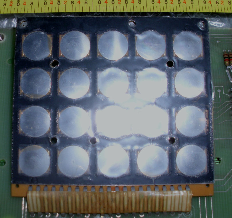
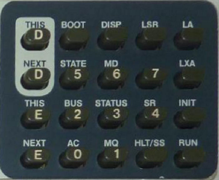
bare keypad which measures 3-1/4" wide and 2-3/4" tall.
And I'll have to mount the PC board pair in some way, and of course cable it up. This will not be pretty. ;) - Herb
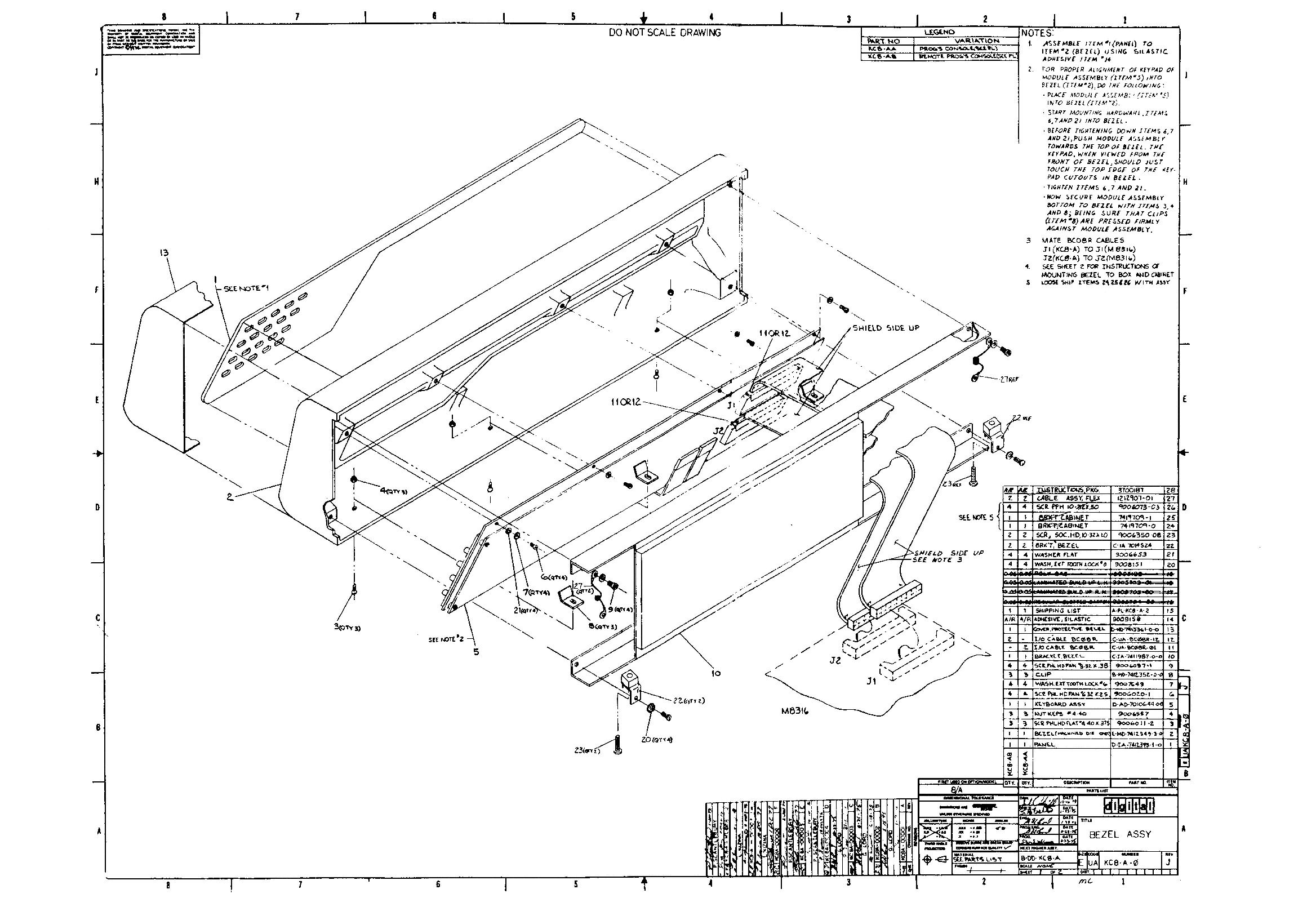
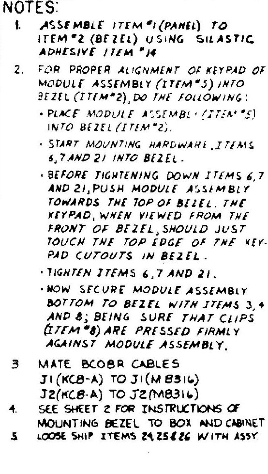
The 8/A Engineering drawing of the KC8-A assembly includes a note on cabling. The drawing shows the connections to the M8316. It's a surprising amount of lines between the, but it's all TTL-class logic. See the pair of 40-pin flat-cable connectors for the cable back to the M8316 I/O board;
The cabling to the M8316 consists of a pair of 40-pin IDC flat cables. I have bunches of these. I chose a pair about 3 foot long. The DEC docs say you can use a cable 15 feet long.. the two boards were bought with the DIP-header cables intact between the two boards.
![[prog panel]](8a_prog_bub.jpg) The keypad has contacts which my technical friend calls "click-disks". The complete panel has some squishy-plastic
array of bumps which cushion the keycaps, and an overlay of molded plastic keycaps on an assembly. For expedicious
purposes I'll ignore that stuff. But I need to put something under the keypad to avoid flexing the keypad wiring
to the PC board. I chose to put a Mylar sheet above the PC board, and then a small bubble-wrap sheet between
the keypad and the Mylar. This provides some spring to the keypad when pushing buttons; that may reduce the
repeated shocks of poking at it.
The keypad has contacts which my technical friend calls "click-disks". The complete panel has some squishy-plastic
array of bumps which cushion the keycaps, and an overlay of molded plastic keycaps on an assembly. For expedicious
purposes I'll ignore that stuff. But I need to put something under the keypad to avoid flexing the keypad wiring
to the PC board. I chose to put a Mylar sheet above the PC board, and then a small bubble-wrap sheet between
the keypad and the Mylar. This provides some spring to the keypad when pushing buttons; that may reduce the
repeated shocks of poking at it.
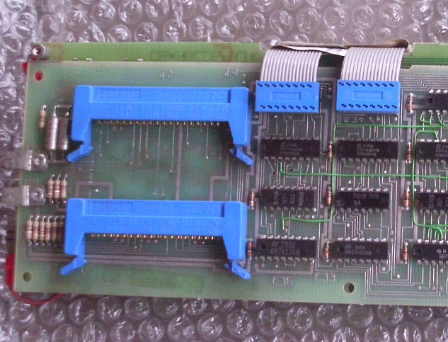
![[prog panel]](8a_prog_pad.jpg) I don't have the cast-aluminum frame and printed-Mylar overlay for the programmer's panel. As I have a few feet
of cable back to the M8316, I may as well consider the panel as "portable". so I simply tied some soft "rubber" foam
to the back of the board-pair. I'll have to sneak the two 40-pin cables into it. Shouldn't be a problem.
I don't have the cast-aluminum frame and printed-Mylar overlay for the programmer's panel. As I have a few feet
of cable back to the M8316, I may as well consider the panel as "portable". so I simply tied some soft "rubber" foam
to the back of the board-pair. I'll have to sneak the two 40-pin cables into it. Shouldn't be a problem.
![[prog panel]](8a_fix_jan16_panel.jpg)
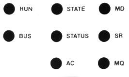
To use this panel, I'll need some kind of overlay to designate the keys and also describe the displays. The LED's are labeled on the PC board but that's not easily read. And no lables for the keypad. So I printed an image of the 8/A keypad and the LED legends; and I mounted them PC board and keypad. Here's the results , used during my late Jan 2016 repairs session at InfoAge.
![[prog panel]](8a_prog_tests.jpg)
The panel worked fine, with no faults, when I operated either David Gesswein's PDP-8/A, or later my own 8/A.
Learn more about my 8/A repair sessions at the VCF Inc repair event at InfoAge.
I asked David Gesswein about testing and setup of the programmers panel:
Q. Is it worth applying 5 volts to the panel for bench testing? Or ohms testing the 5V line, as I only get 60 ohms?
A: I get the same 60 ohms on mine. I think a lot of the logic is on the processor card in interfaces to so likely won't show too much. If the LED's light you can check them. Are the 7 segments HP 5082-7740's? I can bring some spares in case.