![[serial cable]](8aser_connect_map.jpg)
![[serial cable]](8aser_connect_color.jpg)
This Web page last updated date Feb 12 2016. I obtained some PDP-8/A chassis and power parts in May 2015, examined, cleaned, painted, tested and repaired them. In this Web page, I discuss making a serial cable. I used the cable during my 8/A repair sessions in Jan 2016, sponsored by VCF Inc. at Infoage. - Herb
See my other DEC minicomputers as listed on my DEC Web page. To email me, see see my ordering Web page for my email addresses.
The 8/A serial cable off the I/O card M8316, is the same as for the older 8-series serial interface board. Thanks to Doug Jones for his how-to-construct this cable, including current versions of original connectors. Also thanks to David Gesswin for his comments. From Doug's documents, I sketched the chart on the left, for the wiring scheme between the DB-25P (male) connector, and the DEC-designated pins on the PC-mount 40-pin connector.
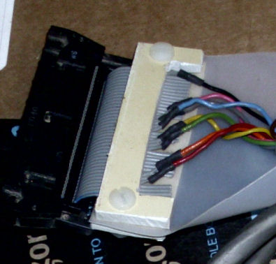
However, I chose out of expediency to cobble together a cable from bits of IDC 40-pin flat cable; soldered to colored twisted wires to the soldered DB-25. A premade DB-25 cable provided the wiring. On the left, you see the mated wires, soldered to the counted-off flat cable wires. Black shrink-tubing covers the joint and adds mechanical strength.
For the 8/A, the only active "EIA" pins are TXD, RXD, GND and (one of the handshakes). For the 8/F serial interface, many more EIA pins are in use, plus others for current loop, etc. I limited the wiring for this cable (and a copy I'll make for my 8/F) to eight of the common RS-232 lines.
Additionally: I omitted a jumper on the 40-pin connector, between the 8/A's EIA to TTL recieve output; to the 8/A's TTL
recieve input. These construction images don't show that jumper. My chart shows this jumper as from 40-pin connector pins E to M. Results below discuss the details.
![[serial cable]](8aser_connect_fit.jpg)
![[serial cable]](8aser_connect_parts.jpg)
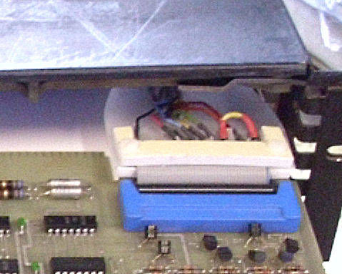
With the assembly inserted into the serial card as shown on the left, I used an ohmmeter to verify the connections, from the DB-25 to the PC board pins. But it's not mechanically strong; any tug on the cable, will put all the tension on the shortest wire-junction. A solution was to clamp the multipair cable to the IDC connector in some fashion. Also, to provide a way to pull the connector out other than pulling at the cable. The solution: another cobble-up, of plastic hardware.
The mechanical pieces are shown on the right. A milk jug provided a long piece of flexible plastic. Some old PVC block, provided 1/8" thick chunks of plastic to act as a clamp. The clamp was cut to be wider than the 40-pin flat cable. The milkjug sheet would also be clamped to the IDC cable near the connector. The other end of the sheet can be clamped to the cable, and also serve as a pull.
![[serial cable]](8aser_connect_recut.jpg)
The assembly is shown on the lower left. I had to trim the length of the clamp, so there was some space from the clamp to the IDC connector. Why? Because for use, the cable will likely run parallel to the PC board, OVER the PC board IDC connector. The bent cable is shown below left. This is not a long-term solution, but should last for months or a few years. Milk-bottle plastic is designed to deteroriate over time.
![[serial cable]](8aser_connect_bend.jpg)
A note from David Gesswein: "On your cable make sure the nuts can't short anything." Good catch! I replaced the nuts and bolts with 8-32 nylon hardware as shown.
Additionally: I omitted a jumper on the 40-pin connector, between the 8/A's EIA to TTL recieve output; to the 8/A's TTL
recieve input. These construction images don't show that jumper. My chart shows this jumper as from 40-pin connector pins E to M. Results below discuss the details.
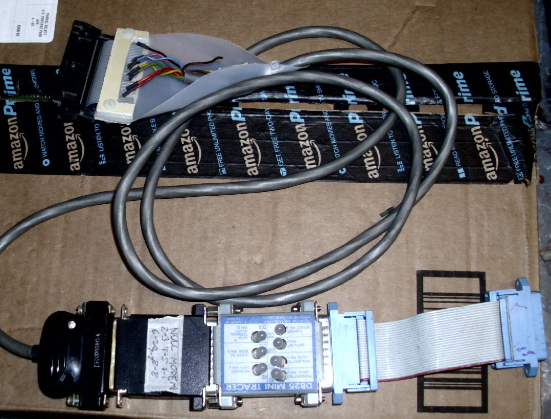
For a convenient terminal I intend to use a Windows/MS-DOS laptop. Those have the so-called "PC compatible serial port", a DB-9 connector. To connect that to the DEC-specified DB-25 EIA connector, I needed various adapters and "null modem". Here's what the bundle looks like. I include an LED line monitor. Quite a bundle, and the DB-25 to DB-9 isn't shown! Note the nylon nuts and bolts, which replaced the metal ones.
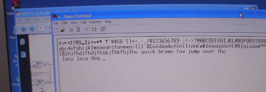
I used the cable during my 8/A repair sessions in Jan 26-27 2016, sponsored by VCF Inc. at Infoage. Here's my Web page about my 8/A repairs on that site, for details. But my cable only displayed output from the 8/A, not serial input, based on simply loopback programs provided by David and in the 8/A User's manual.
The cable required an additional jumper, to connect the EIA-to-TTL output (recieved from the serial line) to the 8/A's TTL recieve input. The interface also supports current-loop, and so has a current-loop recieve output which, alternatively, would have been connected to the TTL receive input. My chart shows this jumper as from 40-pin connector pins E to M.
YOu can see the red jumper I added, on this image of the installed cable
connector. Once added, the cable successfully performed the keyboard echo program.