![[chassis before]](8a_recved_1.jpg)
![[chassis after]](8a_1sttest_trans.jpg)
This Web page last updated date Feb 2 2016, link added Sept 30 2019. Background: I obtained some PDP-8/A chassis and power parts in May 2015, examined and tested them and found some failures or issues. In Sept 2015 I acquired a second power regulator and verified its DC voltages.As another Web page shows, after some testing and small repairs I reassembled them..
As this Web page shows: At the VCFed repair event of Jan 29-30, 2016, I tested on a working 8/A the following: my 8/A board set, my core memory boards, and my programmer's panel. Then I assembled the best of these on my 8/A chassis, and ran tests with some success. My thanks and great appreciation to David Gesswein, who provided total use of his 8/A, and patiently gave me instruction and answered questions, as he worked on another slightly more challenging PDP-8.
In Sept 2019, I worked on this 8/A again, to test some additional Programmers Panels. One of the 8K core boards failed unfortunately.- Herb
To email me, see see my ordering Web page for my email addresses.
See my other DEC minicomputers as listed on my DEC Web page.
Index:
Notes on 8/A chassis repairs, collection of board set, memory, serial cable
Work done at Jan 2015 VCF workshop
Gesswein's repairs of the straight-8
Boards under test and in use
PDP 8/A board set
Core memory board sets
DC and AC ripple measurements
Programmers panel
Serial cable
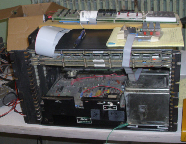
Details are shown on my 8/A repairs Web page. The 8/A chassis was recieved as a chassis with backplane, power regulator, transformer, and limited-function panel. There was rust on the bottom of the chassis. There was some kind of power-up problem reported, but the G8018 power regulator and lim-fun panel were from a working 8/A system. In Spring of 2015, the system was disassembled, examined and component level tested (mostly resistive and diode tests). DEC documentation from bitsavers was gathered and schematics compared to actual parts; some additional parts not in documentation were traced and schematics updated. A few parts were replaced; a cable connection was corrected. Part of the chassis was sanded to remove rust and repainted. DC power tests were good. A second G8018 was tested later and found good.
![[Sat setup]](8a_fix_jan16_setup.jpg)
On my chassis, I checked DC voltages and (on David's advice) AC ripple. Most of the voltages are accessible on fuses on the G80XX card. I had to hunt around the schematic to find convenient locations for +20 and +5, they are fused before the regulator. Results are listed later in this document but voltages and AC ripple were deemded reasonable by David.
Then my boards were individually tested on David's working 8/A. He had the same set of boards as I - the three 8/A standard cards, an 8/A 8K core board. Saturday was a process of learning to operate David's 8/A, then swapping board by board and testing to find issues. I was a little perplexed by David's quick show-me of operating the 8/A programmers panel, but I sorted it out. Particularly challenging was the data display is "one off" from the address display when incrementally adding or examining data.
M8315: David's had SW1 only needed switch #7 on, to disable power-on jump. Yadda yadda yadda, here's the results of my card tests on David's 8/A:
M8315 CPU - works, ran FOCAL; 2nd M8315 s/n ..246 also OK on brief tests Interestingly enough: I discovered David's 8/A, had a mechanical intermittant on his AC fuse holder. The AC power relay would not
always engage when the AC power cable was plugged in. It was stable enough, to not need repair this weekend.
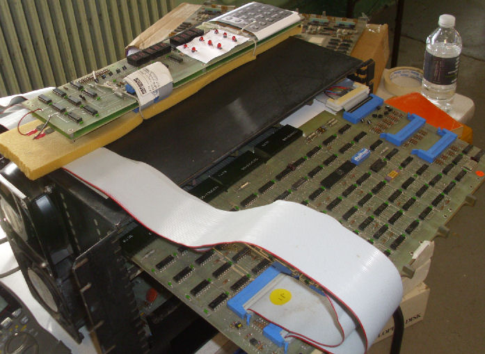
I moved my boards under test to my chassis. with my "soft" 8K core board "1613". Laptop
as terminal and document library; oscilloscope to check DC power ripple with my boards in play. Results are listed later
as compared to Saturday's DC and AC measurements without the boards in chassis.
The three 8/A boards are in my chassis, the M8315 CPU is in the top slot as
required. Below is the M8316 I/O card with the cables out to the programmers panel lying atop the chassis. Below is the M8317.
To the front of the prog panel, is the smaller limited-function front panel, which attaches to the backplane. Of course the chassis
contains the G80something power regulator board, and the large 60Hz transformer to its right.
Good operation of the 8/A programmer's panel board on my chassis! Tests with my 8/A board set and my "soft" 8K core board "1613", were the same as the tests of the same 8K core board on David's 8/A.
The instructions kept changing when run at full speed, but were OK when single-stepped. For subsequent testing of my 8/A, I used
David's known-good 8K core board. I made DC and AC ripple measuments again: check my list of voltages.
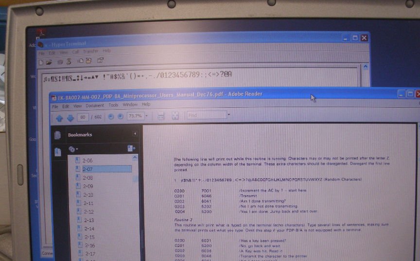
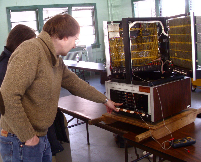
Here's the first test program run on my 8/A. This is with David's 8K core board. It simply
spits out the serial port, the incremented accumulator. The back window is of course the terminal, the front window shows the DEC 8/A
User's Manual page for the program. My three-board set - M8315, 16, 17 - ran fine on my system, despite the apparent problem with
occasional clear-accumulator when the M8316 was run on David's 8/A.
When I tried to run a console echo-character program, my 8/A failed to respond. Stepping through the program showed no character was
recieved. So I had to check the logic path of the incoming EIA character on the M8316 board.
Logic testing on the M8316 I/O card. The card is on David's hex-width bus extender board. For
isolation I put a cardboard sheet under the M8316. It was cut from a Dunkin Donuts box - the right dimensions and good stiff pressboard,
and white for visibility. I'm about to test, to resolve a serial-in problem as described below.
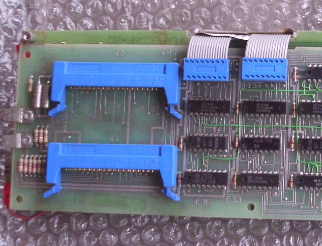
In this photo, the extended M8316 and programmer's panel. You can see the pair of 40-pin flat cables
to the programmer's panel; and the small serial cable at J5 in the upper corner. I'm debugging why the M8316 is not responding to serial
inputs, for the serial echo program. Simple diagnosis: I traced the input on the EIA reciever chip; the schematic told me it was routed
back out on the J5 connector. Why? so the connector could jumper select, between current loop input and EIA input!
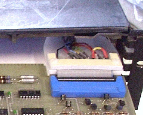
this photo of the upgraded serial connector at J5 shows a red and yellow jumper across the
connector, to connect EIA/TTL input to the TTL serial input of the M8316. The echo-terminal program ran fine after that.
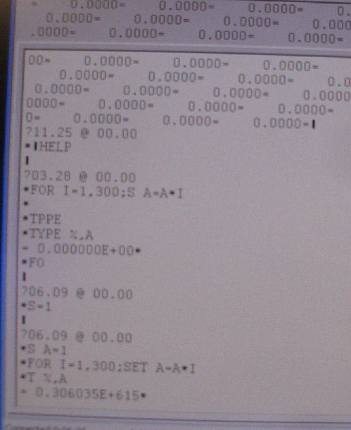
Portion of run of FOCAL on my 8/A with David's 8K core board. FOCAL loaded on the first try! and
it ran successfully - to the extent I could figure out how to use it.
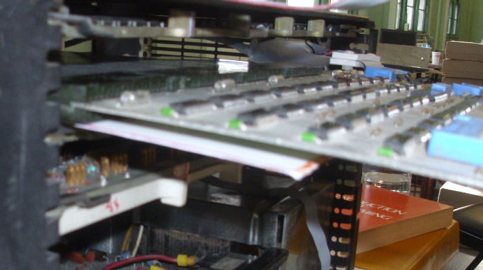
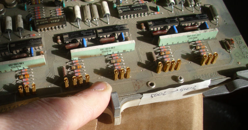
I did a few tests on my chassis, with the 8K core board that occasionally Here's a view of the core driver board. This is the board which has occasionally sets the least-sig bit
after execution on run (not single-step). Those gold upright pins, are contacts between the stacked
pair of core board and driver/logic board. I inspected the contacts to look for obvious corrosion, found none. David says he's never serviced or separated his 8/a core boards. Indeed, my three sets of memory boards still have their DEC seals between the two cards.
David Gesswein's primary mission was the repair of the VCF / Claude Kagan RESISTOR's "straight 8" PDP-8. He was kind enough to coordinate
with me and bring a whole 8/A and some extra memory, so I could test my boards on his system. Fortunatately, I didn't take a lot of his time
as his time was needed to replace bulbs on the straight-8, and to diagnose logic problems. This original 8 uses discrete diodes and transistors
to operate the hundreds of Flip-Chip logic boards. Failing 45-year-old diodes, poor contacts, and fragile bulb wires were challenges David
met, one at a time. When he left Sunday, the 8 was mostly operational at the front panel, but had problems with the flip-flop logic for
accepting serial (current loop) characters from the ASR-33 Teletype. - Herb
David at work on the straight-8. I purchased the 8/A board set below in late 2014 as a tested and pulled set. In May 2015 I obtained another M8315, S/N 598246.
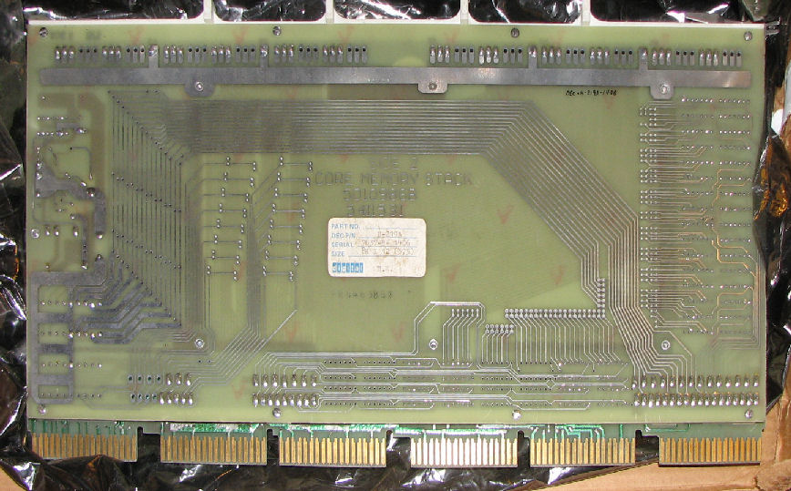
M8315, CPU, front view and no back view. I obtained the following core board pair in May 2009, as untested. In Jan 2016, I recieved two pairs of 8K core boards, as "these hang my system":
core H-219A S/N 7515- - -1489, etch 5010986B, 5411531 core H-219A S/N 7516- - -1613, etch 5010986A, H219 In 2015 Feb I obtained a two-board programmers panel set
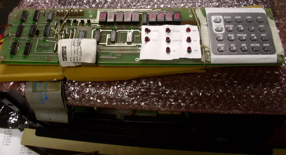
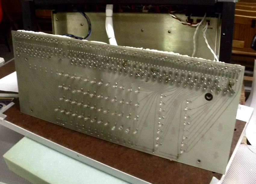
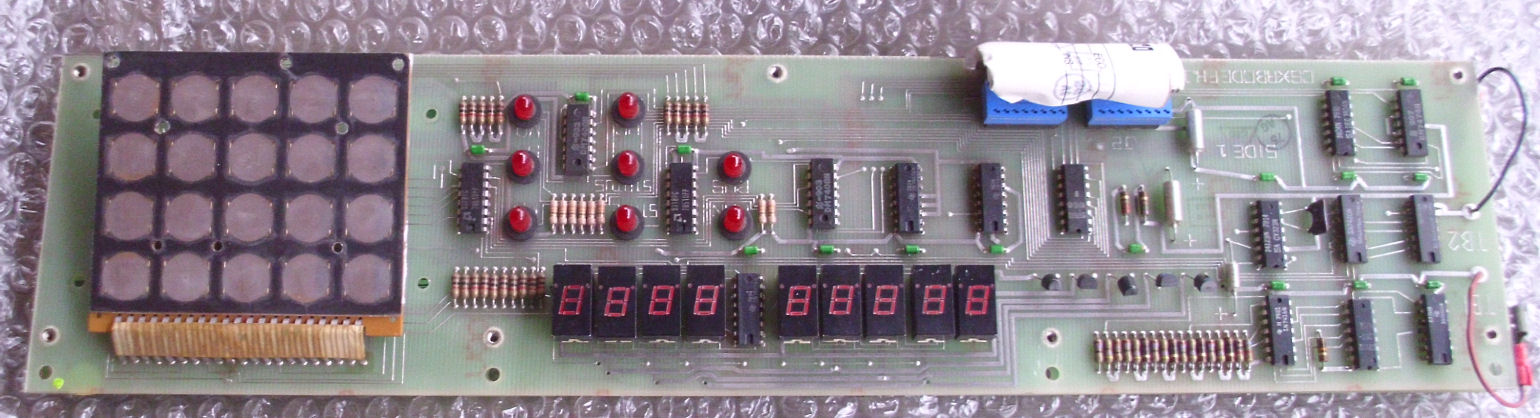
- probably from an OEM PDP 8/A. Condition unknown. The back of the panel
has a pair of 40-pin flat-cable connectors back to
the M8316 I/O board; I can scrounge such cables. But I had to do something about the
bare keypad and lack of display legends. Look at what I came up with for this 8/A programming panel. But as you'll see above, I mounted the dual-board set on some spongy material to insulate the board, put some bubble-wrap under
the loose keypad. And, I laser-printed a photo of the keypad and LED display for identification and use.
For further repair work in Jan 2016, I needed to construct a serial cable assembly, from the
serial connector on the M8316 to an "EIA" serial connector DB-25. Rather than buy the correct parts,
I chose to cobble something up. But I think it will hold up for awhile.
See how I constructed a cable from convenient parts, and fixed a problem during testing. As I described
above, my cable worked well mechanically, but I forgot to jumper the serial-in from the EIA receiver, to the TTL serial input. Worked OK after that. On the 8/A, the only EIA lines in use are transmit, receive, and (um, one of the ready lines...).
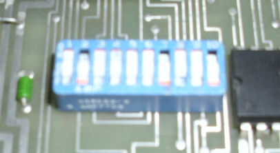
M8316: SW1 1,5,6,9 on for 9600 baud, RTC on, 2 stop bits, fileter out, TS1 settings (page 48 User's Guide)
M8316 I/O - works but sometimes caused a clear-accumlator on an I/O instruction in RUN (but not single-step). Check lines C0 C1 C2
M8317 features - not used much but caused no failures.
programmer's panel - runs OK
8K core boards s/n "1456" - would not take any data, read 0000 octal after prog panel entry.
8K core boards s/n "1489" - 2nd LSB seems to be stuck at 1.
8K core boards s/n "1613" - accept prog panel entry and performs single-step, but LSB gets set occasionally on RUN.
![[Sunday work]](8a_fix_jan16_core1.jpg)
Sunday
Gesswein's repairs of the straight-8
![[David work]](8a_fix_jan16_gess_2.jpg)
The array of bulbs on the 8.
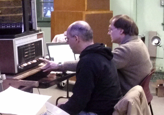
David Gesswein, describing the operation of the straight-8, after his bulb repairs.
David Gesswein (right) showing Evan Koblentz how to operate the straight-8.
Boards under test and in use
PDP 8/A board set
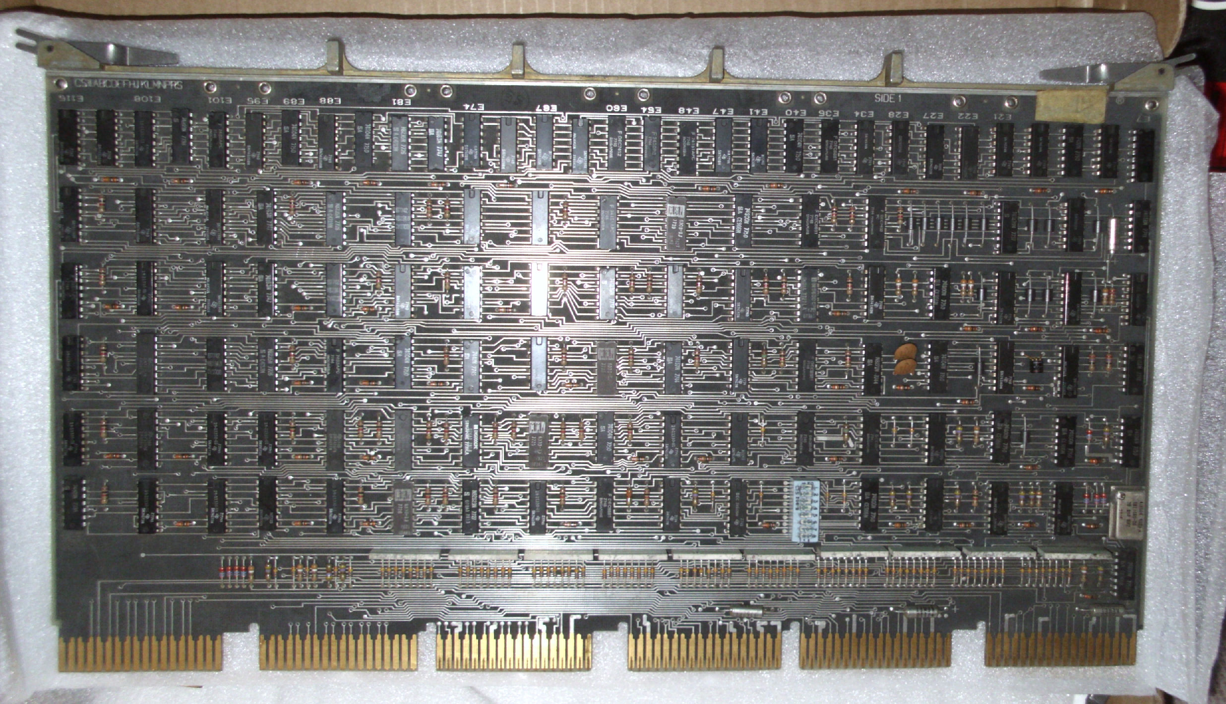
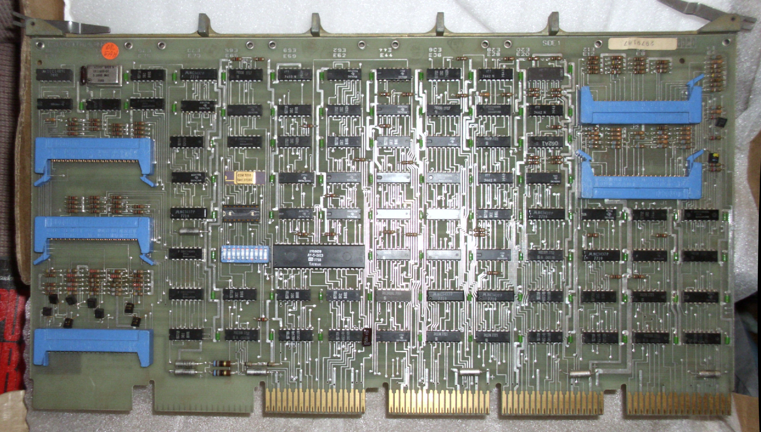
M8316, I/O multifunction, front view and M8316 switch settings.
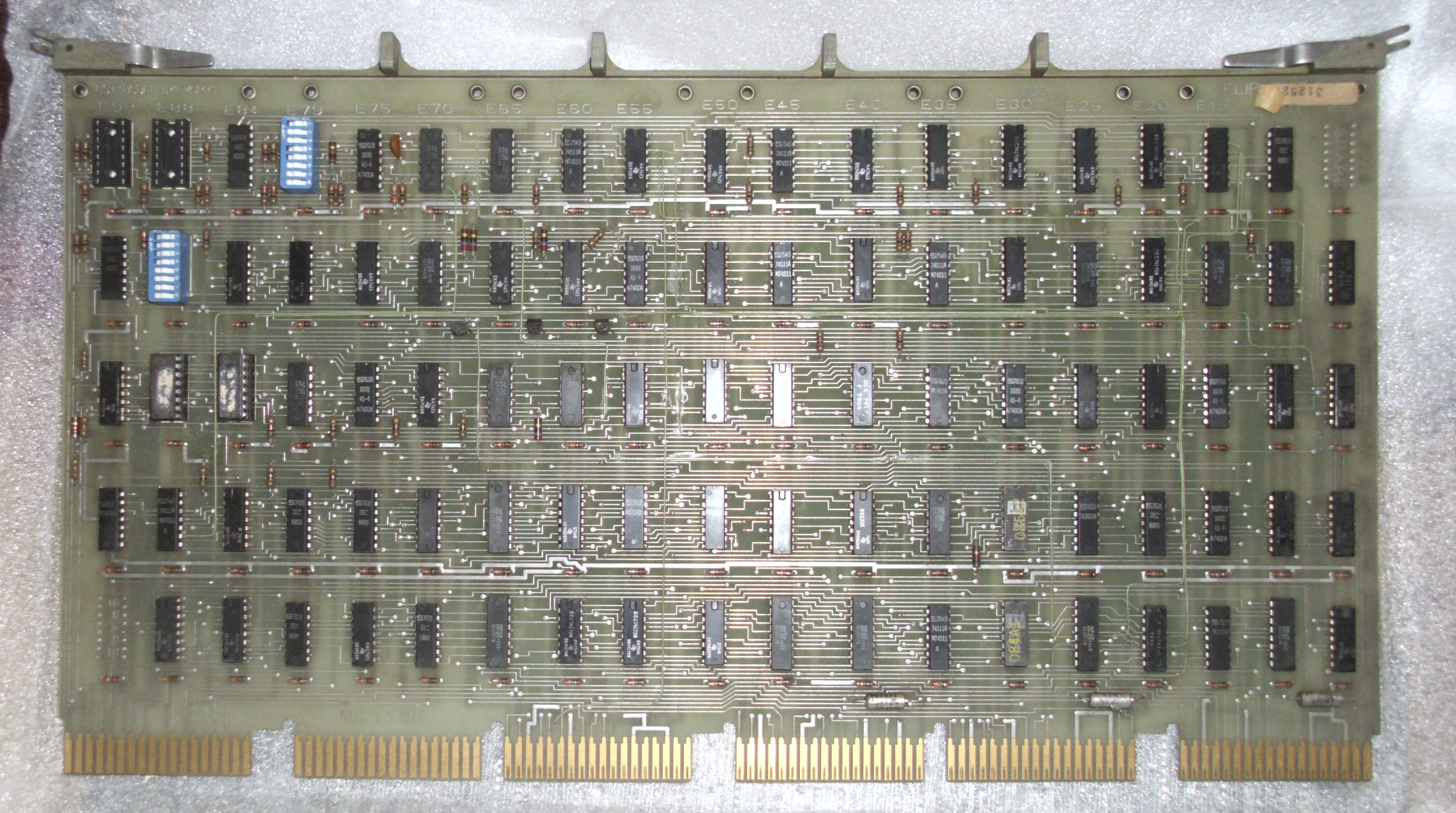
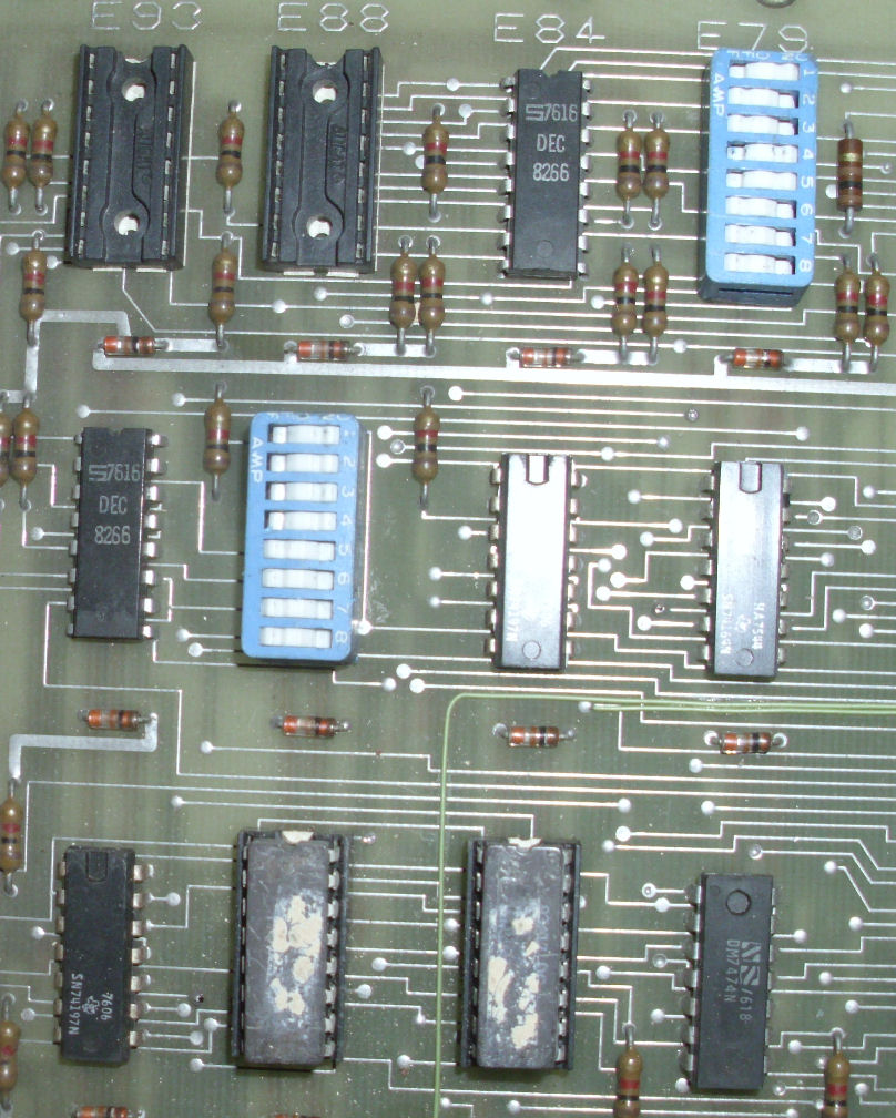
M8317, Extended options, front view and M8317 switch settings and ROMS (lower center pair with damaged labels). This is not the -YB version.
Core memory boards
a H219A core memory card s/n 7637-b-1456 etch 5010986B 5411531.
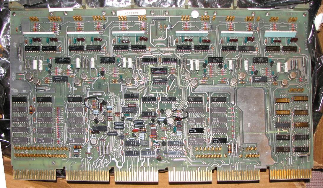
G649 Core x-y driver & sense/inhibit card s/n 4541456.
I'll refer to this board pair as "1456" after the core serial number.
G649?, no lable.
Henceforth core-board pair "1489"
G649?, date 01/16/80, s/n M07110812
henceforth core-board pair "1613"
DC and AC measurements
			noload		logics	logics+core
		DC	AC	DC	AC	DC	AC
28V fuse	+28.49	.20	+27.9	<.2	+26.9	.40
+15V fuse	+16.0	.15	+15.62	<.2	+15.46	.20
-15V fuse	-16.14	.10	-15.2	<.2	-15.06	.15
-5V fuse	-4.97	<.10	-4.97	<.2	-4.98	.02
+8V brkr	+8.27	<.20	+7.1	.6	+7.01	.70
+5 on bus	+4.96	<.20	+4.87	<.05	+4.87	<.02
+20V						+20.12	<.03
Programmers panel
Serial cable
Copyright © 2019 Herb Johnson