![[rev K2 CPU]](mem_k4_cpu_bare.jpg)
![[rev J assembled]](mem_revJ_toggles.jpg)
Page last updated Feb 23 2022.This is the support page for the Rev K2, K3, K4 CPU / Rev J & K front-panel 1802 Membership Cards. K4 CPU is in distribution since June 14 2021. K3 CPU was distributed during Sept 2020 - May 2021. The K2 CPU was in distribution July 20 2019 - Sep 2020. Rev J front-panel was in prior distributions, Rev K front-panel since Sept 2020. See the Chronological section for links to pages and documents for versions prior to the K4 CPU and K front panel.
This Web page contains MANY Web links with support and use information; but there's more background about design changes on previous version support pages. Links to order and for more information are below.
The photo on the left is of the bare Rev K2 CPU board, photo by Herb Johnson. The photo on the right is an assembled Rev J Front Panel 1802 Membership Card, assembled and photo by Herb Johnson. Assembled photos of later boards will look substantially the same.
"For those just tuning in, the Membership Card Kit is a reproduction of the original Popular Electronics COSMAC Elf computer, but shrunk to fit in an Altoids tin! It works the same, and runs the same software." - Lee Hart, developer.
How to order: Order the Membership Card via links from the 1802 Membership Card home Web page. The page has links to current and previous 1802 Membership Card version pages. It also has links to 1802 history, testing, hardware, software, and more.
Product documents
A quality kit for the beginner or vintage builder
Rev K features and options
Initial testing and programming
Rev K detailed description
Engineering & Change Data
Hardware and software and notes about them
Errors, corrections, mods
Chronology of Membership Card products & support Web pages
Prices, ordering, contact
Pages edited by Herb Johnson, (c) 2021 Herb Johnson, except for content created by Lee Hart and others. To report errors on this page, contact Herb at www.retrotechnology.com, an email address is on that page. - Herb Johnson
![[parts kit]](mem_j_kit.jpg)
Documentation K3, 4 CPU and Rev J & K front panel:
The Rev K4 manual is a .PDF file at this link. dated Feb 9 2022.
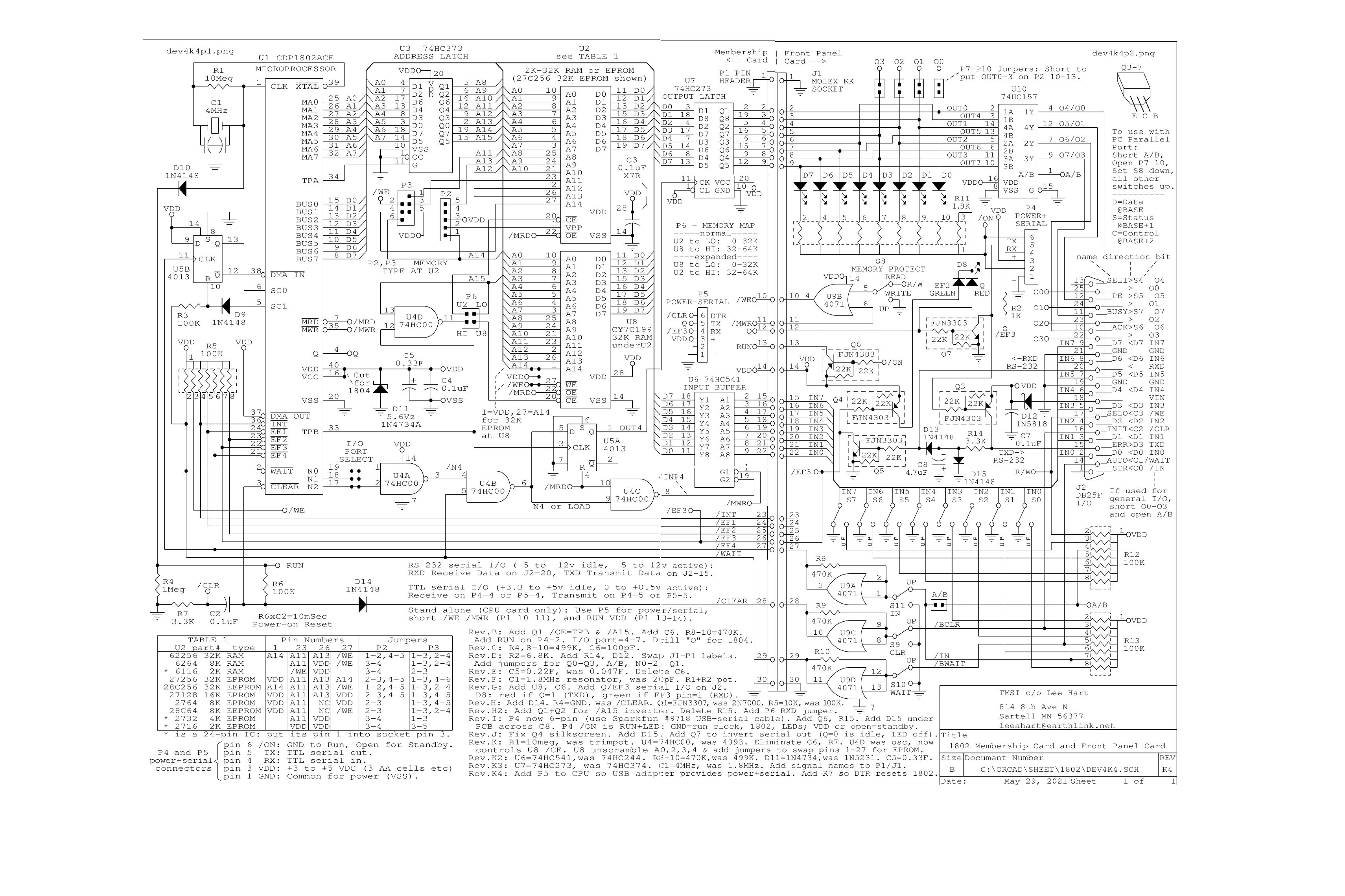
The Rev K4 CPU and K front panel schematic is at this link dated May 29 2021.
The Rev K3 manual is a .PDF file at this link. dated Apr 11 2020.
Here's the link to the Rev K3 CPU and J or K front panel schematic PDF dated Aug 13 2020.
The previous JK2 version documents are on the Rev JK2 Web page.
See the Chronological section for links to these and earlier manuals and Web pages.
Here's the link to the 2019 cheat sheet . Gives the 1802 instruction set, Rev J connections.
On the left is a Rev J kit parts from May 2018; the Rev J & K parts kits look much the same. On the right, is an assembled Rev J front panel, by Herb Johnson.
![[edge view]](mem_revI_build_2.jpg)
Small size, ordinary components, assembly manual for hands-on building. The front panel and CPU boards stack to fit in an Altoids tin. (Rev I stack shown.) The front panel cover board (optional) fits over the Altoids lid.
Only readily-available electronic parts are used (except the 1802) and are part of the kit. Most parts are from the 1970's "ELF" era. All thru-hole parts (not surface mount), for easy hand assembly. Assembly manual guides construction, part by part, with testing and debug information.
Quality printed-circuit board, easy to see, build and repair:
- quality USA-made PC board material, 1 oz. copper, wide 15 mil traces
- quality IC sockets
- many chips tested before distribution
- white, legible "silk screen" text to identify parts and pin functions
- 60 mil large pads, 40 mil holes to fit larger pins or pin-socket inserts
- large holes and pads are easier to desolder misplaced parts without damage
- gives a 70's look to a 1976 processor kit
"On occasion, customers have put parts in the wrong places. They commented [to me] that they were amazed they could remove them without damaging the PCB." - Lee Hart June 2021
Run with or without a PC. For the full product, no PC, external hardware, or any onboard program, are required for use. Front-panel runs, halt, loads by toggling switches. LED binary display. These are same features as the classic COSMAC ELF; plus RAM, ROM and I/O options as described here. For the CPU only, it's operated by a serial link which controls a ROM monitor or a ROMmed BASIC. Or you can put your own programs in ROM or download them via the monitor.
stable clock frequency with ceramic resonator. Rev K4 is sold with a 4 MHz resonator. Previous versions included a 1.7Mhz resonator. Earlier versions included a trimpot to slow that down for lower-power operation.
Low-power standby, nonvolitile RAM: Separating the CPU board from the Front Panel, or disconnecting the power connector, will put the CPU board into a "standby state", program halted and RAM contents saved by the supercapacitor. Save time is hours to days depending.
RAM and ROM on one CPU board The K4 kit comes with .3-inch narrow RAM chip. A ROM can be installed above the narrow RAM, to support a ROM/RAM based monitor. Or you can add a .6-inch wide RAM for an all-RAM computer; a wide RAM was provided with kits before revision K4. A narrow ROM is also possible. The image on the left, shows the Rev H2 assembled in that way, with the ROM out of the socket. You can run the CPU board only, with a TTL to
serial adapter and a ROM monitor with serial terminal support. Assembly and operation is described in the K4 manual. A CPU only kit is now available.
Load/run and data transfer via "parallel port". The front-panel board has a DB-25 connector for 8-bit data in and out; other lines control 1802 LOAD and RUN, and serial. The 8-bit wide DB-25 arrangment matches the traditional "PC parallel port". Old-school PC's under MS-DOS can run programs in QBASIC to download and run Membership Card programs; the Windows OS limits parallel-port operation. Some M/S card owners have built microcontrollers to operate the Membership Card. See this Note about use of the parallel port by old PC's, with links to examples of use of microcontrollers. Rev H and later have more ways to set up the DB-25 connector for 8-bit-wide operation.
serial interface operation via EF3 and Q with an RS-232 interface on one front panel connector pins, a TTL or 3.3V serial interface on another pins. A two-color LED shows serial activity on Q and EF3. Serial operation requires a ROM or program to support a "software UART" and to interact with the serial user. The TTL connector is also the +5V power connector and can be compatible with some USB-to-serial adapter cables and boards. Serial and RS-232 features were discussed in more detail on the Rev I Web page's "Engineering" notes.
Adding a ROM monitor or BASIC: Lee Hart offers ROM files or ROMS for a ROM BASIC and an 1802 ROM monitor. Follow the link for details on this Web page. Other monitors or programs, from Lee Hart or others, can be run from your own ROM or from RAM, see the software notes below.
Changes from earlier revisions: Details of recent changes are later in this document. Some components have been changed over time; and there were earlier versions with a variable clock circuit; and various kinds of serial interfaces; and various system signal changes. Earlier revisions are documented on other Web pages linked-to at the end of this Web page.
To order: Refer to the Membership Card home page for the current ordering status. An email address and Web link takes you to developer Lee Hart for ordering and contact.
The kit manual has test programs and debug information; ROM monitors and BASIC ROMs are also available. Also, see this document on Testing the 1802 Membership Card with small toggle-in programs. Basic operations of the front panel are described. There's more links about testing and use, under "features" on this Web page. Other links are to testing hardware Web pages and testing software Web pages are on listed on the home Web page. - Herb Johnson
The 1802 Membership card set, consists of a CPU board stacked on a Front Panel board, with an optional Cover Board atop the toggles. Or, you can run the CPU board alone. Also, you can buy a prototyping board for your own circuits. You can buy ROMs for a monitor or for BASIC; or burn your own ROMs from images provided. You can buy the boards, or a kit with boards and parts; or partial kits. And, you can buy a Cover Board, a circuit board to cover the switches and lights of the Front Panel card. These are all sized to fit an Altoids tin box. All boards (except the cover) accomodate the CPU's 30-pin expansion connector. The Front Panel provides a 25-pin D-sub connector for specific I/O; the signals compliment the ancient "parallel port" of the IBM PC.
![[Rev K2 CPU]](mem_revK2_cpu_bare.jpg)
![[Rev K4 CPU]](mem_revK4_cpu_top.jpg)
Rev K2 CPU bare board on right; left is the layout of the K4 CPU. The K3 replaces the K2's 74HC374 with 74HC273; K4 has a number of small changes.See the Engineering section for specific changes.
- 1802 microprocessor (option for 1804/5/6 which have no load mode).
- .6-inch 24-pin socket for 2K to 32K byte-wide RAM or ROM, selected by P3 jumpers
- dual-use of a 27C512 ROM, select one of two programs at power-up
- also .3-inch 24-pin socket under ROM/RAM for narrow SRAM or ROM.
- supercapacitor to maintain RAM contents with power disconnected or /ON asserted
- HI/LO jumper select on board ROM/RAM for high or low 32K address space
- board cuts to select U8 as narrow ROM not RAM
- optional +5 volt power input at DB-25 pin 18 w/diode protection (jumper selected)
- K4 adds 6-pin serial/power connector P5 for one-connector to USB/power dongle
- diode to /CLEAR for power-on clear
- ceramic resonator for stable clock 4.0 MHz in full kit
- the usual 1802 I/O bits (Q, EF1-EF4, INT, etc.) and OUT4 IN4 decoded and buffered
- IN/OUT4, control, serial and power brought out to a 30-pin header (pins labled)
- size: 3.5" x 2.125"
- power: 3-6vdc at several mA (depends on clock speed and choice of ROM and RAM memory chips)
![[Rev J front panel]](mem_revJ_front_bare.jpg)
![[Rev K CPU]](mem_revJ_fpback_bare.jpg)
Rev J front panel bare board on left. The Rev K front panel adds labels to the 30-pin connector.
- plugs onto the 30-pin connector of the Membership Card CPU board
- no PC, external hardware, or any onboard program, are required for front-panel use.
- read/write memory, run/clear, run/load toggle switches
- 8 data output LEDs (memory reads and OUT4)
- 1 input and EF4 pushbutton to load front-panel switch data
- 8 data input toggle switches (memory writes and INP4)
- provides the Elf front panel interface and "classic PC" DB-25 parallel interface,
- one 8-bit output port (OUT4 default, or you can jumper-select others)
- output port multiplexed to four DB-25 pins (PC parallel port)
- OR all 8 bits out to eight DB-25 pins (jumper selected)
- one 8-bit input port (INP4 default or you can solder-jumper select others)
- serial interface with activity LEDs for  EF3 and Q.
-  serial receive, transmit connections, build to support TTL/3.3V, or RS-232 voltages.
- size: 3.5" x 2.125"
- power consumption: milliamps plus 1-3ma for each LED lit.

DB-25 PC parallel port connector on Front Panel:
- has all I/O and control signals to classic PC parallel port (8 bits in, 4 out)
- can control run/halt/load front-panel operations
- jumpers to bring out all 8 bits and bring in +5 on DB-25

6-pin serial/power connector
- RX/TX GND and +5 volts compatible with some USB-to-serial adapters
- adds "idle" signal, could be connected to serial (TTL level) RTS line or a toggle switch.
- one pin is removed, to key the cable connector so to avoid a reversed connection.
![[panel cover]](mem_revJ_frontpanel.jpg)
Cover board on left as part of Rev I built kit. Built by Lee Hart.
The Membership Card Cover Board is a PC board to cover the Altoids lid and mounts on the Front Panel board. The board has holes for the switches and lights, power/serial connector, and DB-25 connector. There's silkscreened labels and a tinned copper shield on the back. Cut a large rough rectangular hole in the Altoids box, and solder or epoxy this board to the top to provide a neat finished front panel.
![[protoboard]](mship_proto_1.jpg)
The Membership Card Protoboard is a PC board for prototyping and development. It mounts on the CPU board instead of, or potentially underneath, the Front Panel board. It's sold
seperately from the 1802 M/S Card kit or board set. See this Protoboard Web page for more details.
Lee Hart provides ROM images for monitors, BASIC and other programs. From mid-2021 Lee offers a ROM and RAM kit. Details and documents will be on Lee Hart's ordering Web page, get there by links from the 1802 Membership Card home Web page. Currently the ROMs available as images and/or as prepared ROMS include:
MCSMP20 series of ROM monitors with BASIC3;
Tiny BASIC;
Chuck Yakym's MCSMP Super Monitor plus BASIC3;
Mike Riley's Elf/OS diskless ROM with many programs.
Go to my Membership Card home page for a Web link, to developer Lee Hart for ordering and contact.
The clock speed is now 4Mhz from the supplied ceramic resonator. There's an additional header to configure the memory map. P6, the low/high memory jumpers, don't need a PC board cut, jumpers must be in place.
Lee Hart noted: "I added P5, a 6-pin header, to the CPU board. It's a duplicate of P4 on the Front Panel, and allows a Sparkfun (or other) USB-serial adapter to be plugged directly into the CPU board when it is used stand-alone. I decided to start supplying 0.3" wide RAMs as standard (instead of the 0.6" parts)." This makes it easier to add an EPROM at U2.
"I added R7 (3.3K) in series with the GND end of capacitor C2. The top end of R7 goes to DTR pin 6 of P5. This is done so DTR can reset the 1802. TTL USB-serial adapters normally leave DTR high when your terminal program is "off-line" or "disconnected". When you go "on-line" or "connect", DTR goes low. The falling edge of DTR is coupled through C2 to pulse the 1802's /CLEAR pin low. R7 also limits the peak current into the 1802's /CLEAR pin's protection diodes if the supply voltage suddenly goes to zero (such as by shorting the power supply). This is an unlikely failure mode, but it can happen."
"I added names to the 30-pin header pins on the CPU board. I already did this on the rev.K Front Panel, but figured I might as well have them on the CPU board as well. "
"[The new CPU boards] are marked K3. No functional difference, but I did change U7 from 74HC374 to 74HC273. Pinouts and functions are the same, except '374 pin 1 was low (0=output enable) and is now high (0=clear on the '273)." Compare the K2 and K3 CPU schematics for details. The Rev K front panel adds labels on its 30-pin connector [not on the Rev J front panel board]."
The Rev K2 and earlier CPUs have a 74HC244 to buffer the INP 4 toggle switches. Lee Hart says: "Replacing the 74HC244 with the 74HC541 eliminates the [brief] high power consumption in the special case of going from CLEAR to LOAD, before you press IN for the first time. It [occurs] because the 1802 has a special "initialization" cycle after CLEAR that grounds the data bus. At the same time, the 74HC244 input buffer was trying to put the Front Panel switches onto the bus, [in preparation] for the first IN cycle."
Oscillator operations: The Rev J CPU had a 4093 CMOS logic gate to operate the 1802 clock, but the gate limited the run frequency. In Rev K and K2, the 1802's oscillator driver circuit is in use. The now-available gate, now a 74HC00, is used as the A15 logic-inverter, replacing two MOSFETS as the previous inverter. Lee Hart reports the results: "It at least doubles the speed. It eliminates the trimpot, 2 MOSFETs, a resistor, and a capacitor. It cleans up the layout, by getting rid of C6 and R7 (that were hiding under the EPROM), and I don't have to hand-machine every EPROM socket to get around those components." - Lee Hart
"The 1802 oscillator is shut down via a diode, through a logic low on the RUN signal. Lee describes this: "When RUN is high, the diode is reverse-biased; so all it adds is capacitance. You want capacitance anyway; the resonator itself has about 40pf. This is required for stability. This capacitance, and the resistance of the XTAL output of the 1802 form an RC network to keep it from oscillating on some harmonic."
Also for Rev K and later CPUs, "I added jumper options to use a 27C256 "skinny" EPROM at U8. Basically, these let you connect pin 1 to A14 or VDD, and pin 27 to /WE or A14." - Lee Hart. Also, in previous revisions four address lines to U8 were "scrambled". In Rev K and later, they are now unscrambled and in normal order. See correction notes below for details about RAM versus ROM lines at U8.
![[U8 as ROM]](mem_revk_U8_rom.jpg)
Lee Hart, Feb 18-20 2017: "There's a "catch" with using an EPROM in the U8 0.3" wide RAM socket on the Membership Card. The pinouts are different between RAMs and EPROMs, [and need to be rewired] as follows. Pins 1 and 27 have to be reversed: There are jumpers to do this on the Rev K CPU board." Leave the board alone to use U8 as RAM; cross-wire to use U8 as ROM. Here's an image of the bottom of the Rev K CPU PC board, of the two wide traces on U8 pins 1 and 27. Refer to the Rev K CPU PC board images on this page to get oriented.
PIN#	EPROM	RAM
-----	-----	---
1	VPP	A14
27	A14	/WE
In previous revisions, the 1802 address lines A0, A2, A3, A4 to U8 were scrambled. This doesn't matter for a RAM; but it does matter for a ROM! In Rev K, the address lines to U8 are in the correct order. Here's a Tech Note with details for previous revisions Or refer to the support Web page by CPU board revision for details.
To add a 300-mil wide RAM at U8, a 0.1uFd X7R axial-lead ceramic bypass capacitor must also be added. It might be necessary for a narrow ROM. Parts for a narrow RAM, ROM monitor and serial connection, are described on this linked Web page.
Discussion of the front-panel P4 connector, by Lee Hart and Herb Johnson, updated July 2019. Also see the Rev I Engineering notes about the P4 connector which operated differently. . With CPU board rev K4, there's a similar connector on the CPU board for single-board operation.
Unplugging the P4 power/serial connector, removes power and lets the /ON signal float high. The /ON disable stops the clock, resets the 1802, disables the LEDs, and puts everything in "standby" mode, powered by the supercapacitor. The standard kit comes with older "slow" all-CMOS parts and 600-mil-wide RAM. So power consumption is essentially zero in standby, and the supercapacitor will maintain memory for hours or days.
If you upgrade memory with modern "fast" cache RAMs or faster non-CMOS EPROMs, power consumption will be higher. So the supercapacitor may only hold RAM memory contents for minutes or hours. Some (not all!) CMOS EPROMS with "C" in the model name, are really low power. Slower usually equals lower power. For instance, National 27C256Q 450nsec is low-power. Two "real" CMOS 300-mil RAMs I've identified are Hitachi HM62256BLSP and Sony CXK58257ASP. See this Web page for tests of various 300-mil RAMs and some further discussion.
Various non-critical components in the kit, may have different values from the current or previous manual. Typically these are like pull-up resistors, or the super-capacitor, or some I/O logic chips. Look at the Engineering Changes for design changes. In this section I try to document errors and solutions, or useful changes after/during construction which are optional. Previous revisions each have their Web pages with manuals and other changes. - Herb Johnson
From Lee Hart, June 15 2021: "I built [the K4 CPU] myself, following the new [K4 manual's] directions. So far, I found one challenge: My new batch of supercapacitors (C5) are a bit bigger in diameter! So the black plastic body of P5 (the new 6-pin USB adapter header) hits C5. I had to file away a little bit of the black plastic body to make it fit. (I corrected the PCB layout so this will be fixed in the next PC board order.) - Lee Hart
Some time prior to Nov 2019: "R8-R9-R10 [on the front panel] were 400k, now [they are] 470k". Also, on the CPU board, "D11=1N4734, was 1N5321". The 5.1V 1N5321 zener which protects the 5-volt supply, started conducting well below 5 volts; the 1N4734 5.6V zener "draws 0.4ma at 5.0v, and a negligible current below 4.5v". Quotes from Lee Hart, details on this low-power Web page.
Inverting /EF3 serial input: If you need to invert the P4 serial TTL input on the Rev I or J front-panel card, here's a means described by Al Williams. He provided this description, in his notes about use of the Spare Time Gizmo's version of the "ELF2K" ROM monitor on the 1802 MC. "The solution I used, was to clip R2 off the circuit board completely. Then I wired the left pad of R2 (which connects to P4) to the banded end of D13. This uses Q5 as an inverter. This is equivalent to jumpering [the TTL serial input pin] to pin 20 of the DB25 connector." - Al Williams, July 2017.
Dual-use of 27C512 ROM A 27C512 PROM holds 32K of program and data. That's bigger than most COSMAC programs and "ELF" product ROMs. The COSMAC on reset, runs a program at 0000H - you can address the ROM there. But a trick makes it easier to select one of two ROM programs to run on power-up. Lee Hart: "I can burn two versions into a 32k EPROM; one placed at 0000h in the ROM, one at 4000h in the ROM - both assembled to start at 0000H. Install this ROM at U2, and set the address jumpers for U2=LO, U8=HI.
- If you jumper U2 as a 32k 27256 (P3 = 1-3, 4-6), you have the 0000h-located code at 0000h. This Web site has dozens of Web pages about hardware, software, operation and upgrades and debugging of the Membership Card. Please, please look at the Home Page of the 1802 Membership Card for links to those notes. Collections of hardware note Web links and software note Web links are on these linked pages.
Here's operation of the Rev J M/S card with BASIC 3 and an FTDI-chipped USB serial adapter. Some details and history of BASIC 3 and USB serial adapters
are below.
June 2021: Diskless Elf/OS ROM available Diskless Elf/OS ROM by Mike Riley gives you a taste of everything! It has Tiny BASIC, FORTH, Lisp, VTL2, a monitor, simulator, a mini-editor/assembler, and XMODEM
upload/download. See links to the 1802 Membership Card sales page to get the binary ROM image and find more details.
2018: Lee Hart and Chuck Yakym provide a BASIC, Tiny BASIC, and ROM monitor, as binary images you can download to burn into a PROM. See Lee's 1802 M/S card sales page, look under under "BASIC for the 1802". Choose the "Rev J" version for your rev J CPU board. Details are in the ZIP files and on his site. There may be in-development versions on the cosmacelf Yahoo Web site in the "files" section, "Basic 3" folder by Chuck "the-eagle". again, choose "Rev J".
June 2017: Many people use a USB to serial adapter to operate the 1802 Membership Card serial port. Over time, it's been discovered that these adapters introduce hardware buffering of characters sent and recieved. This buffering interferes with timing delays caused by 1802 software, and delays deliberately added by "terminal" programs on the PC in use. Here's a Tech Note which is from discussion of these issues, taken from the cosmacelf Yahoo discussion group. - Herb Johnson
June 2017: Many people want to use a USB to serial adapter to operate the 1802 Membership Card serial & power port. Check the Rev I Engineering notes for some considerations about the power/serial connector.
These USB devices require "software drivers", which aren't always easy to install and use. Different USB "chips" give different results. Over time, it's been discovered that these USB-chip adapters, introduce hardware and software buffering of characters sent and recieved. This buffering interferes with timing delays caused by 1802 software, and delays deliberately added by "terminal" programs on the PC in use. Here's a Tech Note which is from discussion of these issues, taken from the cosmacelf Yahoo discussion group. - Herb Johnson
Jan 2017, various ROM programs: Lee Hart says "So far, I have tested [the 1802 Membership Card] with the following ROM monitor programs: Dec 2015: Lee Hart looks at some TTL to USB and DB-9 RS-232 to USB adapters. Here's what he has to say. Further
notes about the art of bit-serial on the 1802 M/S card is on this how-to Web page.
In June 2014, David Kriest assembled a Rev G CPU card as a stop-motion video. See the video
on Youtube as "MC Revg" by "Corecoder" for June 13 2014.
To order: Refer to the Membership Card home page for the current ordering status. Web links there take you to developer Lee Hart's Web site for ordering and contact. The 1802 Membership card has had many design changes: to improve operation, provide more user options, or to correct problems. Review previous version's support Web pages for discussions of those changes, or for guidance about use of the current version. Consider buying a new-version CPU or front-panel card versus modifying your version. There's often links to notes about such "mods" on the previous support pages.
Dec 17 2021: improvement to the Rev K4 kit include a 4.0Mhz ceramic resonator, machine-pin
low-profile sockets.
June 14 2021: Rev K4 CPU is in distribution with Rev K front panel. Several small circuit
changes made, see the Engineering section for details. The Rev K4 manual is a .PDF file at this link.
June 2021: Diskless Elf/OS ROM available Diskless Elf/OS ROM by Mike Riley gives you a taste of everything! It has Tiny BASIC, FORTH, Lisp, VTL2, a monitor, simulator, a mini-editor/assembler, and XMODEM
upload/download. See links to the 1802 Membership Card sales page to get the binary ROM image and find more details.
Sept 2020: Rev K3 CPU is in distribution until June 14 2021. Sold with Rev J front panel until Jan 2021; or with K front panel later. Rev K3 CPU changes U7 from 74HC374 to 74HC273 The Rev K front panel adds labels on its 30-pin connector. The Rev K3 manual is a .PDF file at this link.
Nov 2019: There's a "special" one-card version of the 1802 Membership Card kit. It's just the CPU board [and critical parts]. See the 1802 Special Kit Web page for details and how to order. This offer ended by 2022.
July 20 2019: Rev K2 CPU is in distribution; Rev J front-panel is still in distribution. The K CPU's 74HC244 input buffer was replaced with a 74HC541 on the K2, to eliminate extra power consumption during the time between CLEAR and the first LOAD cycle. The Rev K2 manual is a .PDF file at this link. See the JK2 Web page for details.
Jan 21 2019: Rev J2 CPU was in distribution until July 20 2019; Rev J front-panel was still in distribution. The CPU's 4093 is replaced with a 74HC132 to improve logic-switching speed.
Aug 1 2018: Rev K CPU was in distribution until Jan 20 2019; Rev J front-panel was still in distribution. "This NEW [Rev K CPU] version is simpler to build, uses less power, and runs at higher clock speeds (with a faster resonator)." - Lee Hart, July 1 2018. The Rev K manual is a .PDF file at this link.
July 1 2017: Rev J CPU and Front-panel boards were in production,
the CPU board until about July 2018. A transistor was added to the Rev J Front-Panel board for the Q LED. See the Rev J Web page for details.
Feb 1 2017: Rev I Front Panel in production, now with a power/serial connector. The H2 CPU was still in distribution, until April 2017 and Rev I with minor changes. Some problems of use were found, see the Rev I page for details.
July 2016: Rev H2 Front Panel in production with Rev H2 CPU. A 3.3K resistor R2 was added in series with the RS-232 input; as a change to Rev H.
June 2015: Rev H2 CPU in production with Rev H F/P. The Rev H CPU /A15 address inverter NPN transistor Q1 replaced with 5LN01SP N-channel MOSFET and 5LP01SP P-channel MOSFET to produce the /A15 signal (chip-select for memory at 32-64k). Rev H2 CPU also has a normal 4-pin header for [HI/LO] memory address selection, located on the top of the board.
Check the 1802 M/S Card home page, for links to ALL previous version Web pages. Further details of production and change history are on a history of production Web page.
40 years ago as of 2018, Lee produced an 1802 single board computer called BASYS. Look at the BASYS manual for hardware interface suggestions for the Membership Card.
Refer to the Membership Card home page for the current ordering status. A Web link takes you to developer Lee Hart's Web site for ordering and contact.
This page and edited content is copyright Herb Johnson (c) 2021.
Contact Herb at www.retrotechnology.com, an email address is available on that page..
- If you jumper U2 as a 16k 27128 (P3 = 1-3,4-5), you have the 4000h-located code at 0000h."
- Lee Hart
Hardware and software and notes about them
- Herb Johnson's IDIOT monitor
� Chuck Yakym's monitor + Tiny BASIC at cosmacelf Yahoo
� Spare Time Gizmo's Elf2K EPROM
Recent History of 1802 Membership Card production.
How to Order