![[solar 1802]](mship_solar.jpg)
Last updated Nov 14 2019. Edited by Herb Johnson, (c) Herb Johnson Contact Herb at www.retrotechnology.com, an email address is on that page.
This Web page describes testing and construction, and documents the low-power operation of the COSMAC 1802. One section is about constructing a low-power 1802 Membership Card, by Herb Johnson. Another section shows a demo model produced by Lee Hart. There's a note about Zener diode current draw. Described in a backround section are links to background about the 1802 COSMAC processor, the currently-available 1802 Membership Card, and a number of support Web pages for that kit and the programs used in this demo. - Herb Johnson
This is a rev.F 1802MC with a solar panel to power it. To keep the power down, it has ultra-bright LEDs, the clock speed set to minimum, and only 2k of RAM. The solar panel is on the cover of the Altoids tin cover. Open the cover so it is exposed to light when operating the computer.
There is an ON/STANDBY switch. "ON" draws about 0.6ma plus 1ma or so for each LED lit. "STANDBY" draws less than 50uA. To get the lowest standby power, set the WAIT switch up, and the CLEAR switch down.
The solar panel delivers about 5v at 20ma in sunlight (which will fully charge the supercapacitor in a few minutes). Or about 2.5v at 100uA in typical ("my") room light. That's enough to run the computer, but not the LEDs continuously; but it will hold memory indefinitely. Note that the RAM write-protects itself below about 2.4v.
A lamp with a 60-100w tungsten (not fluorescent or LED) bulb makes enough light to power the computer continuously. I use a Luxo lamp exactly like this (ebay# 252834704970) shining on the solar panel. - Lee Hart, written March 2017
Update May 2017: I have an 1802 Membership Card on my desk for playing with. It has a little solar panel on the lid, which provides all the power (no batteries). On a sunny day with the solar panel facing the window but sun not shining directly on it, it will run continuously, LEDs and all, on just light. Or, it runs for a few hours on just the supercapacitor (LEDs off), or 10-15 minutes with the LEDs, depending on how many are on. The only change from the "stock" version is that the LEDs with super-bright versions, and their series resistor is 3.3k instead of 1k. [And] one [Membership Card] I measured recently draws 3 microamps when idle. - Lee Hart
Herb Johnson: I'm working on a demonstration of the 1802 Membership Card, a COSMAC ELF derivative, as a low power microprocessor. This demo produces codes in LED and audio based on a radio message sent decades ago through the Areciebo radio telescope. Power will be by a solar cell and either battery or supercap to retain collected power. The program is loaded using the very small IDIOT monitor, already in ROM.
I describe and put to use the "Arecibo program" later. For purposes of developing the hardware, "short and long blinks to represent binary data" is an adequate description of the intended software. In fact, for my testing program I used a simple "blink the Q" program I toggled into the M/S card. (That program is in the assembly manual for the M/S Card kit.)
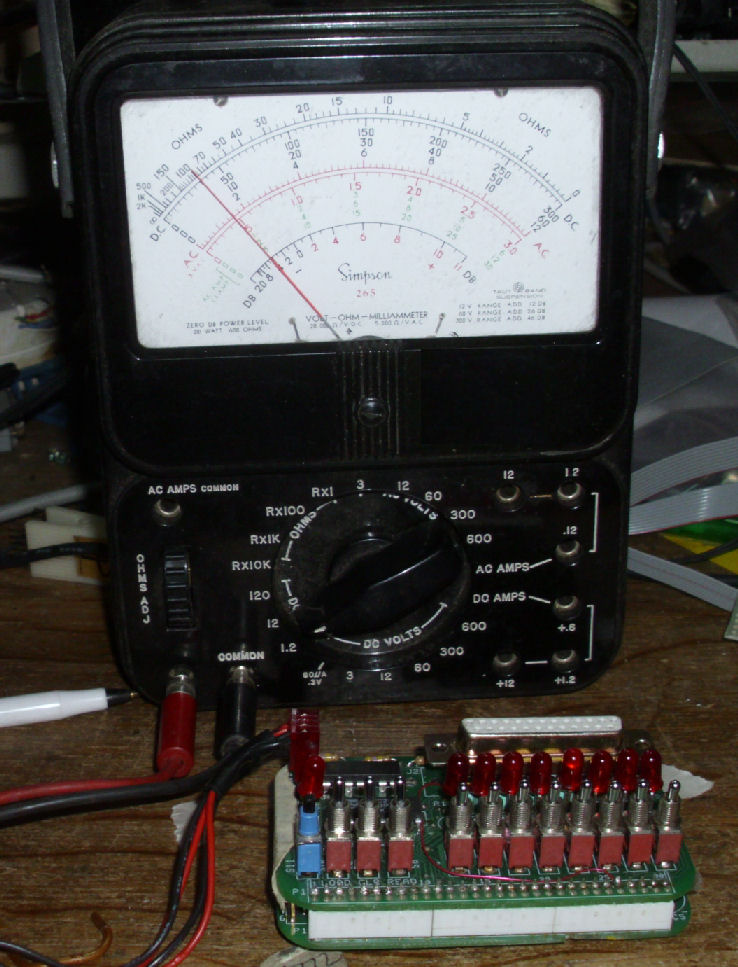
In the linked photo, a meter shows under 2mA current (12mA full scale) of TOTAL DC power to the Membership Card, blinking Q (data output) LED, plus an LED accidently left on for the address display. At 4.2V tired battery power, that's under 9 milliwatts power to operate the computer and LEDs - and some of that is the front-panel LED. (Q: why did I use an ancient analog meter and not a digital meter?)
![[arecibo breadboard]](are_bread1.jpg)
Blinks are hard to follow; tones less so. I obtained a piezoelectric buzzer from Radio Shack, to add to the binary output port. Piezos are low power noisemakers: this unit was rated at 10mA at 6V. To provide plenty of current, I designed a one-transistor circuit or "driver". When the input is "high", the PNP transistor comes "on" and the buzzer buzzes.
I prototyped it on a breadboard first, and got it working. The large image
on the left of this Web page, shows a sketch of the circuit; the three AA battery power; the Membership Card (less the cover board); and the breadboarded buzzer circuit. The Piezo only adds 2mA more current draw
when on, as measured by my DC meter.
The NPN transistor can be any; I used a 2N2222A. The buzzer is a Radio Shack 6V low current model 273-0054. There's a 10K resistor on the base of the transistor, the size is not critical. The Q data out signal is pin 15 of the DB-25; pin 19 is one of the grounds; pin 18 is DC power. (Earlier versions of the M/S card did not bring out power, I wired my M/S card to match recent versions.) The circuit is common-collector or "emitter follower" in ancient jargon. When the base is driven "high", the transistor is "on" and the emitter drives the buzzer "on". When the base is "low", the transistor is "off" and there's no collector-emitter current.
![[proto]](are_proto2.jpg)
Then I wired up a circuit board which mounts on the Membership Card DB-25 connector. The board holds the piezo, a DB-25, the transistor driver. It's convenient to have boards that you can just add and remove from the Membership Card's DB-25. Currently that's how my serial interface is wired up; the older version of the Membership Card I use did not have a serial interface on the front panel board.
![[arecibo breadboard]](are_speed.jpg)
With the buzzer circuit tested and prototyped, I reassembled the M/S card with its external serial interface, to download the Arecibo program under the IDIOT ROM monitor and serial interface. My older M/S card has an external serial interface; now-current versions have the interface on the switches/LED front panel.
To run the ROM monitor, the M/S card clock circuit must be run at full speed. But to run the Arecibo program, the clock must be slowed down, as the "blink" rate is determined by a simple software loop. Also: slowing down the 1802 clock, reduces power consumption (because the microprocessor spends less time switching around - speed becomes watts). The photo on the left, shows the M/S CPU card as I adjust the CPU clock trimpot (blue block) to slow down the clock. (The M/S card kit manual describes this feature.) The supercap on the CPU board (lower right, circular part) preserves the RAM contents for DAYS while power is removed and the CPU is unclocked.
Here's the 1802 program listing which produces the Arecibo message. {Links to support Web pages are below.) The program runs a loop to read data from a table, convert the data bytes to bits. The bits are "output" to produce for a "1" a long on-time for an LED, and for a "0" a short on-time. As in the original message, the length of the message in bits is a number divisible only by two numbers; when the bits are arranged in rows and columns by those numbers, a blocky image appears which represents astronomical information about the Solar System and Earth.
It's simple to operate the Arecibo program once downloaded, since it is loaded at address 0000, where the 1802 starts execution upon reset. From the Membership Card's toggle switches "load" position, the "reset" is toggled up/down once (unnecessary but safe), then two switches are flipped from "load" to "run from address 0". The front panel LEDs happen to display the last examined memory location. [Lee Hart later noted the front panel can be disabled from the DC power connector.]
In my tests, the memory read/write switch is NOT flipped; the program RAM is in read-only mode. Thus is demonstrated that the Arecibo program can run in ROM, which is my current plan. The IDIOT ROM monitor is not necessary to run the Arecibo program.
Lee Hart built a model of the Galileo spacecraft, which holds a 1802 Membership Card to "broadcast" the Arecibo message, in beeps and blinks. Galileo used several 1802's, and orbited Jupiter to obtain data and photos of the Jovian system. My bit of work confirmed the program would run from ROM and otherwise operate in a current Membership Card.
Because a digital meter failed! When I hooked a cheap digital voltmeter to the 4-volt, few-milliamp circit as a current meter in series, the Membership Card just crapped out. Ohm's law told us the circuit is drawing milliwatts (2ma X 4 volts). To measure current without sucking power away means I need a MICROwatt instrument. The DVM simply grabbed too much circuit power to make the current measurement. An analog current meter typically can measure tens of MICROamps - just to move a needle with a magnetic coil. So this "ancient" instrument does not load down this "modern" microcomputer circuit. Call it "retro-technology". - Herb Johnson
Lee Hart: Can you wire the piezo and LED in series? That would reduce power (and reduce piezo volume), but maybe it's still enough? Some of the piezo buzzers are annoyingly loud. Herb replies: I was going for low power consumption, and piezos are efficient. But it's an annoying sounce so my next try will be a 555 timer and PC-mount speaker.
Lee Hart: There is also a jumper you can open to disable the onboard LEDs. I also suspect Q can directly drive the piezo and LED. The low state is rated at something like 1.6ma at 0.4v, which means it behaves like a 250 ohm resistor. Herb replies: I was protecting the Q output with a transistor, and at 7 cents each they are not expensive. 555's are well under a dollar, and in fact little speakers from dead PC motherboards are "free".
When Lee updated the Rev K2 CPU board, he changed the protective Zener diode D11 across the 5-volt supply, from a 5.1V Zener to a 5.6V Zener. Why? It previously drew too much current, even near 5 volts. "Zener diodes under 5 volts have a very poor "knee". Zeners above 6v perform much better. Between 5-6v, they gradually transition from "poor" to "good". The 1N5231 0.5w at D11 was drawing a lot of current at low voltages. It's rated at 5.1v at 20ma, but still draws 10ma at 5.0v, 2ma at 4.5v, and still draws 0.5ma at 4.1v."
"I changed it to a 1N4734 5.6v 1w zener to reduce this effect. It's rated 5.6v at 43ma, but only draws 0.4ma at 5.0v, and a negligible current below 4.5v." - Lee Hart Nov 14 2019
![[card and tomatos]](membership_done2.jpg)
The Membership Card I used, is an early version with a ROM/RAM upgrade: the latest version in 2014 has both. See the home page for the Membership Card for current version and ordering information.
The "Arecibo" program is a means to represent the binary message sent into space decades ago using the Arecibo radio telescope. The 1802 was not used at that time of course. Here's a Web page about the 1802 program, to encode and send data once sent through Areciebo. Here's a history of the COSMAC in early spacecraft - among the first microprocessors in space.
The ROM monitor I used to load the Arecibo program into RAM, is called "IDIOT". It's based on an early RCA 1802 ROM monitor called "UT4". Here's a link to the IDIOT Web page. That page has links to the UT4 Web page if you are interested. Also, links to an 1802 cross assembler written in C and compiled for the Windows (XP and earlier) "MS-DOS command line".
This page is copyright Herb Johnson (c) 2019. Some content on this page, belongs to the authors so named, and is used with their permission. Contact Herb at www.retrotechnology.com, an email address is available on that page..