Last updated JUn 29 2020. Edited by Herb Johnson, (c) Herb Johnson, except for content written by others.
These are notes for supporting the Lee Hart 1802 Membership card with a program to download and upload software, via a Windows/Linux/PC parallel port to the M/S card DB-25 connector, designed to "match" the PC parallel port. This note describes details of signals and connections to the M/S card to load and run programs and transfer data. These notes apply to any load/run interface for the Membership Card.
Chuck Yakym in early 2011, built a Rev B M/S Card kit, and created a Windows 32-bit program (XP, 7) to access and program the Membership card through the PC parallel port. Details are discussed below.
Here are links to other Web pages, about non-PC/Windows hardware & software for operating the M/S card via the DB-25 connector:
Home page for M/S card hardware notes.
Web page for serial interfaces, using the IDIOT monitor (or a monitor you obtain)
Bill Rowe's "olduino" is an aggressive M/S Card interface to an Arduino, plus a C compiler for the 1802, to support some Arduino applications run by 1802 programs. It's a very impressive set of work by Bill, over many years.
There's a Raspberry Pi loader for 1802 M/S card by Len Bayles, produced Dec 2017.
....and the groups.io cosmacelf email list has many discussions and files about COSMAC ELF and derivatives including work done by owhers of the Membership Card. Check the cosmacelf.com web page as well.
- Herb Johnson
I don't know much about Linux. But Fabio Battaglia knows something about Linux. He's apparently adapted a PC parallel port under Linux to upload and download into the M/S card. Look on github for his ELF Membership Card parport loader. of Sept 2014. There's a Youtube video also. The wiring isn't detailed but look at the C source code for the handshake lines; the rest I presume are PC port data lines, probably bidirectional. - Herb
Windows OS's after Windows NT will not run MS-DOS programs with calls to the parallel port I/O addresses. Later OS' will give a protection error. There are ways around this "protection", by using DLL's which work with Windows. The janaxelson.com site among others, discusses these I/O protection issues, and provides a DLL called Inpout32.dll. Recent Web searching (2020) says this DLL is only for 32-bit Windows. A varient is of course Inpoutx64.dll for 64-bit Windows systems. HEre's a 2020 found site which provides some open-source which may be helpful. Check other sites for varients and discussion about use of these DLLs.
Another programming problem is the appropriate BASIC or C compilers. The Windows/DOS-32 C compiler I (Herb Johnson) use, LCC-32, is a 32-bit MS-DOS or Windows, but pre-Win-NT, compiler. It won't produce old-school "16-bit" MS-DOS application programs. Early MS-DOS OS's are "16 bit" and need a different C compiler (example, Borland Turbo C).
A suggestion to me has been to use Watcom C, which has versions for either 16-bit or 32-bit.
Please note: one can run "MS-DOS" programs in Windows systems as command-line programs under Window's "command prompt" window. Ask your Windows help for "MS-DOS" or "command line" to find it. Otherwise one has to use a BASIC or C which provides a "Windows environment" wrapped around your program, with the libraries needed to do that.
In the "old days", MS-DOS based PC's included QBasic or "QuickBASIC". With a text-based IDE, and interpreted (not compiled) BASIC, it's easy to create little (and big) programs incrementally. My old 80486 system with Win 3.1 includes it, and I'm using it to mess with the parallel port with the "PC Port Dongle" attached. Here's a QBASIC program to send bits to the parallel port.
Note that of the four output control lines on the parallel port, one is active HIGH, the others are active LOW. So your program logic must be aware of that.
Here's software and notes about Josh Bensadon's QBASIC program to control the M/S card via the PC parallel port. Again - QBASIC runs under MS-DOS, not 32-bit Windows with that protection error.
Chuck Yakym in early 2011, built a Rev B M/S Card kit, and created a Windows 32-bit program (XP, 7) to access and program the Membership card through the PC parallel port. His program was released in March 2011 as "free/shareware" as a binary (no sources) compressed installable. It is available from the groups.io cosmacelf discussion group file archive, and also available from me by permission. The program is written in Visual Basic 5.0 and uses inpout32.dll. He provides switch-setting instructions for using the Membership Card with the parallel port.
- Herb Johnson
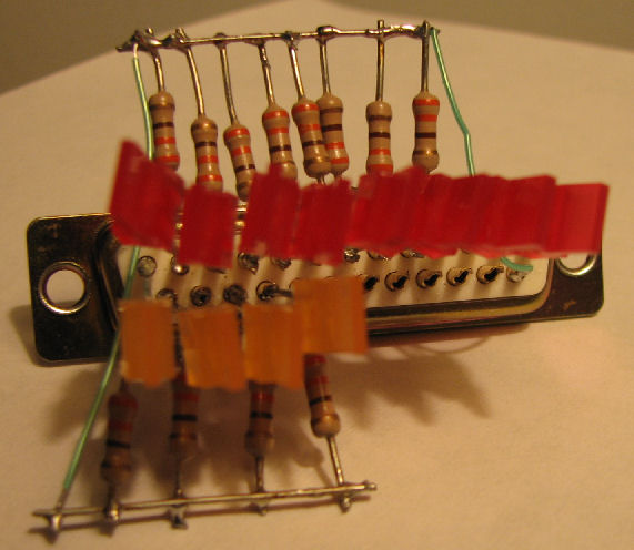
To verify the operation of my program, I built this LED dongle to display the parallel port lines. It simply consists of LED's with 330 ohm resistors to ground. The LEDs are wired so that when an output is HIGH the LED is ON, so the low side of the LED is to ground. I used red LEDs for the data lines, orange for the control out lines. - Herb Johnson
Base I/O address for parallel ports

        MDPA    no MDPA
 LPT1   0x3BC    0x378
 LPT2   0x378    0x278
 LPT3   0x278     n/a

MDPA means monochrome display and print adapter - the original video/print card on PC's.

Register addresses within the parallel printer port:

Port            R/W IOAddr      Bits    Function
----------          ------      -----   ----------------
Data Out        W   Base+0      D0-D7   8 LS TTL outputs
Status In       R   Base+1      S3-S7   5 LS TTL inputs
Control Out     W   Base+2      C0-C3   4 TTL Open Collector outputs
    "           "     "         C4      internal, IRQ enable
    "           "     "         C5      internal, Tristate data [PS/2]

Data Feedback   R   Base+0      D0-D7   matches Data Out
Control Feedbk  R   Base+2      C0-C3   matches Control Out
    "           "     "         C4      internal, IRQ enable readback

Note: some parallel ports are bidirectional. I've not documented that here.

Control OUT Register:  bits vs Pins vs 1802 pins:
"active LOW" means a 1 in the register is a LOW condition on the pin.

bit0 - strobe pin 1 (active LOW), to clock through the IN button the /DMA-IN flipflop on the RISING edge.

Also to steer pairs of input bits via U9.
bit1 - autofeed pin 14 (active LOW), to the OFF postion of "LOAD" switch to /WAIT and also gate data IN latch U6.
bit2 - init pin 16 (active HIGH), to the ON position of "RUN" switch to /CLEAR.
bit3 - selectin pin 17 (active LOW), to the R/O position of "R/W" switch, the /WE line of the RAM.

status IN Register: bits vs Pins vs 1802 lines: active HIGH unless noted.

bit3 - error pin 15, to Q and LED D8
bit4 - selectout pin 13, to D4 or D0 via U9
bit5 - paperout pin 12, to D5 or D1 via U9
bit6 - ack pin 10, to D6 or D2 via U9
bit7 - busy pin 11 active LOW?, to D7 or D3 via U9

Active LOW means a logic 1 produces or reads a ground voltage; active HIGH, a logic 1 is five volts or so.
Lee Hart wrote these instructions in Feb 2012, with some updates in June 2020. In 2012 he advised how to download software via direct (high speed) control using the parallel port and signals not available from the DB-25. Further instructions on the exact sequence of switches and signals are in the next section of this Web page. - Herb
When using the PC parallel port, set *all* toggle switches UP, except the read/write switch which should be DOWN (to enable writing to RAM). For relevant 1802 MC versions: The A/B jumper if present must also be installed, and the four o0, o1, o2, and o3 jumpers must be open if present.
You need to power the 1802MC with an external power supply of 3v to 5v. Most PC parallel ports work at 5v; but if your PC happens to use 3.3v for its parallel port, power the 1802MC at 3.3v, 3.5v or so as well. [A future update will refine this 3.3V advice. Use a voltmeter and look at your PC's parallel port pins for the highest voltage, to decide how- Herb]
Operating the 1802 MC via the PC parallel port, is almost identical to operating it with the front panel switches. The PC parallel port is just setting the switches instead of you. The only "trick" is the multiplexer that outputs the high/low nibble depending on the state of the IN switch.
You want to put the 8 data bits on the Membership Card's D0-D7 (J2 pins 2-9 of the PC parallel port connector. Then pulse IN low (J2 pin 1, called STROBE by the PC parallel port) with a strobe pulse.
Here's what LOAD mode does on the Membership Card:
- The falling edge of STROBE does nothing.
- The rising edge of STROBE sets flip-flop U5B.
- The /Q output of U5B goes low, requesting DMA-IN.
- The 1802 does a DMA cycle, and writes whatever is on the
data bus into RAM. It takes 8 clock cycles to complete
the write, so the time depends on the trimpot that sets
the clock frequency.
- When the DMA cycle starts, the 1802 sets SC0 high.
This clears U5B and removes the DMA-IN request, but
once started, the DMA will progress to completion.
- SC0 will go low at the end of the DMA cycle; the falling
edge of SC0 would normally be your "cycle completed"
handshake line. Unfortunately, it's not brought out on
any pin.
- You might also use the rising edge of /MWR to signal the
end of the DMA-IN cycle. It is brought out on the 30-pin
connector J1/P1 between the boards. But it also does not
come out the 25-pin parallel port connector.
- Lee Hart
Note: the STROBE advances the 1802 during DMA, so you can control loading externally without a "handshake", as long as your data rate is slower than the DMA cycle (8 clocks).
These are under revision as of Jan 19 2019. - Herb
Lee Hart wrote these instructions in 2012, on using the Membership Card's DB-25 with an Intel/Windows/Linux PC. Note: to run the M/S card through the PC port, toggles CLR and WAIT should be up, and R/W should be down - so those signals are connected to the PC port.. In 2019 I thank Robert Parker for his comments and corrections. - Herb Johnson
To load a program into the 1802's memory, and run it, [these PC parallel port lines must be operated as follows below. "Pulse low" means a high signal that's briefly low; likewise for "pulse high". "Set low" means a persistantly low signal; likewise for "set high".]
- set INIT (pin 16) low and set AUTOFEED (pin 14) low (puts the 1802 in LOAD mode)
- set SELECTIN (pin 17) low to enable writes into 1802 memory
- set D0-D7 (pins 2-9) to the byte to write into 1802 memory
- pulse STROBE (pin 1) low to write the byte and increment the address
- set AUTOFEED high to end load mode (INIT still low, so 1802 is reset)
- set INIT high, and the 1802 runs the program you loaded.
To read the contents of the 1802's memory [via the parallel port]:
- set INIT (pin 16) low and set AUTOFEED (pin 14) low (puts the 1802 in LOAD mode)
- set SELECTIN (pin 17) high to make 1802 memory read-only
- set STROBE (pin 1) low to read 1802 low nibble:
... Q0 is on SELECT (pin 13)
... Q1 is on PAPER (pin 12
... Q2 is on ACK (pin 10)
... Q3 is on BUSY (pin 11)
- set STROBE high to read 1802 high nibble:
... Q4 is on SELECT (pin 13)
... Q5 is on PAPER (pin 12
... Q6 is on ACK (pin 10)
... Q7 is on BUSY (pin 11)
- set STROBE low to increment to next address and read its contents
Note: rev D and later front-panels, have jumpers to permit an 8-bit write from the PC to the Membership Card. This document has some details.
While the 1802 is in RUN mode:
- D0-D7 are inputs that get read by the 1802's IN5 or IN7 instruction
- Q0-Q7 are outputs written to by the 1802's OUT5 or OUT7 instruction
- the 1802 Q output can be read on ERROR (pin 15)
- the 1802 /EF4 flag input can be set by STROBE (pin 1)
- Lee Hart
This page and edited content is copyright Herb Johnson (c) 2020. Copyright of other contents beyond brief quotes, is held by those authors. Contact Herb at www.retrotechnology.com, an email address is available on that page..