![[rev G with IDIOT, serial dongle]](mem_revG_blue_serial.jpg)
Last updated Oct 9 2018. These are notes about using USB adapters, or RS-232 type connections, for the serial interface on Lee Hart's COSMAC 1802 Membership Card. Follow this Web link to the 1802 Membership Card support "home" Web page, and to ordering and other information.
There's more USB notes in a Tech Note of online discussion of USB product selection and use. Here's a Web page on how to use FTDI-based boards and the FTDI Windows driver.
Version I and later of the M/S card-set, also includes a TTL serial interface as part of the power connector. That can can be connected to a USB to TTL adapter for serial communications and for DC power. The 1802 M/S Front-Panel card, includes a DB-25 I/O connector, configured to connect to a classic IBM-PC parallel port. That cconnector also has two pins for the serial interface; that connection is also discussed in ths Note. About older versions of the 1802 M/S card: These notes were part of a Tech Note on use of the IDIOT ROM monitor, ROM and RAM, and serial interface and how to construct the interface and use that ROM.
Please consult the Web page for your version of the 1802 M/S card; links for each version are at the Membership Card "home page" linked above.
recommended TTL to USB products?
In late 2016, Lee Hart likes the Sparkfun FTDI Cable 5V, DEV-09718 a USB - RS-232 cable with embedded FT232RQ device, at $17.95 as of April 2018. Drivers are available at links on the Sparkfun site; or at the ftdichip.com Web site for that chip. It's a full-sized USB connector at one end, and a 6-pin connnector supporting TTL logic at the other end. The TTL end fits recent (post 2016) versions of the 1802 M/S card power/serial connector; it can be wired to earlier versions. The adapter supplies 5V (not 3.3V) to the M/S card, and has a line to reset the 1802. Lee says he uses it, many customers use it, and they've had few problems. They've had more problems with other, cheaper USB/TTL devices and their OS (Windows, Linux) drivers. If the seller's Web site doesn't have FTDI-232RL or RQ drivers, check the FTDI manufacturer's Web site for "Virtual Comm Port (VCP) FT232R drivers and for docs on the driver and chip.
Since the 1802 M/S Card Rev I, the front-panel board has a six-pin serial/power header, with TTL levels for Q and EF4 (used for serial) and reset. The linked Rev I document provides details. Lee says: "The Sparkfun #9718 (DEV-09718) cable plugs right in; no pin scrambling needed. The only change I make is to remove pin 2 from the header on the 1802 Front Panel, and then block the cable's hole for pin 2of the Sparkfun connector with a piece of a toothpick). This "keys" it so you can't plug it on backwards. Early 1802 M/S Card revs A-H2 have a 4-pin connector at P4, so you need to connect the Sparkfun RX and TX signals to either the 30-pin header, or to pins on the DB-25 (and assemble for TTL, not RS-232 levels)." Refer to your version's manual on its Rev support page for details.
Lee also says, "of another Sparkfun product, "SparkFun FTDI Basic Breakout - 5V" DEV-09716 for $15, is a board not a cable. "I have tested this, and it works as well. The drawback is no cable; you have to make/scrounge up your own [cables at each end]." He adds, "It uses RTS instead of DTR for handshake/reset control. That might matter with some PC terminal programs. But the ones I've tested (Hyperterm, Procomm, Realterm, Teraterm) all switch both on/off together; so the difference is invisible to the user."
Herb Johnson tested a FTDI-chipped USB/TTL board in May 2018. It has a pinout that also matches the Rev J front-panel power/TTL connnector. Here's a Web page on how to use similar FTDI-based boards and the FTDI Windows driver.
Prior to 2016, Lee Hart and friends evaluated various TTL to USB solutions for the 1802 M/S Card. Lee discusses some products on this linked Web page of earlier notes. Whatever TTL/USB product you obtain, be sure to obtain the correct operating system "drivers" for that product - for the specific chip inside that product. Other considerations are below.
General considerations to use a USB serial adapter with the 1802 Membership Card:
1)DB-9 or wires? If you buy a USB serial dongle with a male DB-9 connector on it, that matches the connector on old PC-compatible serial ports. Details of that DB-9 connector are discussed on the IDIOT ROM monitor, ROM and RAM and serial Web page. These "cables" are sold on many Web venues.
If you buy a tiny "TTL to USB" board, or cable with a serial-to-USB chip on it, you may connect its wires or pins, directly (or through resistors), to the 1802 M/S card configured for a "TTL" interface. Check your 1802 M/S card version's docs for more information. If the board is "3V3" or 3.3 volt, the M/S card is 5 volt; you may need series resistor to the USB card's inputs - check its documentation.
2)software driver adjustments? With many USB-to-serial devices, you'll have to figure out a few "driver" things. You may need to adjust USB serial-port operating parameters, through features of the Windows or Linux device driver. Your results may vary, due to the low baud rates and delays of the 1802 M/S card; and features of the USB device and device driver.
All these details, unfortunately, turn out to be complex and technical. This was revealed in an email discussion in mid-2017 on flow-control and drivers and comm programs under Windows.
For details on the driver for your USB/TTL device, go to the chip manufacturer's Web site for the driver and and documentation for it. You may find driver-use notes on some Arduino or Raspberry Pi Web site where that USB/TTL adapter is supported or used. For details on your comm program, "read the fine manual". ;)
A) Does the USB device work with 5-volt signals or 3.3V? If 5-volt, the Membership Card provides 5-volt signal - read the manual for your M/S card front-panel revision. You might need to remove C8 from the serial interface, which produces negative voltages (read the manual). If your USB device expects 3.3V signals, you MAY need to add resistance - probably 2.2k but do some homework - between your chip and the M/S card Transmit and recieve. Lee Hart adds: "The 1802MC rev.I works with *some* USB adapters set to 3.3v levels. I checked it out with a couple I had, and they worked. But customers have had other adapters that did NOT work. I don't know why. So 5v levels are "safer"."
For Rev I Membership Card front-panel owners, read the Rev I manual for updated information. But Lee Hart told me on Mar 2 2017: " The new Rev.I board works with either 3.3v or 5v USB-serial adapters. It has series resistors on the serial lines, in case you are running the Membership Card at 5v and the USB-serial adapter is using 3.3v levels."
B: Does the chip expect inverted or noninverted data? You may need to try the four-versions of IDIOT (or to modify your 1802 ROM monitor or software) to see which one works, go back and read those instructions. Or, more difficult, see how the Windows or Linux driver can change the expected "logic" of the serial TTL lines. The driver documentation may include notes and software on setting parameters; there may be options in your operating system's "control panel". YOu may have to Web search for examples.
C) How does the USB chip in your device, buffer the data? It turns out, these USB chips have character buffers, which make flow-control from Windows/Linux/MS-DOS programs "useless". For example, a Windows program that introduces character delays between output characters is wasted - the USB dongle simply stores all the incoming characters and spits them out serially at any speed. Likewise, if an external serial device provides a RTS signal to "stop", it's not clear that the USB dongle will obey it - it may send a few more characters anyway! This sort of behavior is discussed in a Tech Note on USB dongles and adapters.
Note that software control of the virtual serial port - which is how ordinary "serial terminal emulator" programs access the USB-as-serial device - may not work! You can set baud rate and stop-start features. But "flow control" will only talk to the USB buffer - not the serial output. Most use of these USB adapters, expect modern devices at both ends, with no delays in processing!
In Sept 24 2018, Lee Hart discussed "flow control" - the buffering of serial bytes or signaling to stop or stop their flow - in some discussion in the Yahoo cosmacelf email list.
Flow control (both hardware and software) worked on my old PC XT running DOS with a real 8250 "ACE" UART and Procomm modem program. When you sent an XOFF, or dropped a handshake line, the UART finished sending a character already started, but then stopped.
If you use a modern 16C550 type UART that has an internal FIFO, the UART will keep sending characters from the FIFO until it is empty even if a hardware handshake line tells it to stop.
If you are running a Windows terminal program like Hyperterm, Teraterm, or Realterm, it is slow to respond to a software handshake. During the time it takes to notice the XOFF, characters keep getting sent.
USB-to-serial adapters add their more levels of delay. The PC sends data to them in packets, and the USB adapter tries to send a whole packet (like an entire line) to the serial device at once. There doesn't seem to be any consistency in how long they take to notice a hardware or software handshake request. The worst of them ignore handshaking completely. - Lee Hart
In reply to the discussion, Mark Molding noted that while Windows can "report" the size of a serial transmit buffer - it's almost always ZERO because the hardware "drains" the buffer to a UART or to a USB device. He was forced to do "math" - how long it takes to send characters times the number of characters sent - and force a timer delay and hope that was enough. In further discussion of how to support, say, 19.2K baud, it was noted that speeding up the baud rate was somewhat moot, as slow 8-bit processors (the COSMAC 1802 in this case) simply don't provide or accept data in millseconds anyway.
The resolution of these buffering and flow-control problems may require adjusting the Windows or Linux device driver operations. Those OS's and device-driver software may include "advanced control" or management features. Those include hardware and software flow-control (XON/XOFF, RTS/CTS) and buffer size and time delays. Apparently, USB dongles and their software drivers, don't "expect" low-baud rate or interrupted flow-control applications. In short - these are a challenge for use on vintage computers! Read the discussions referenced for further notes. - Herb
Some people still use old computers with serial ports. Old computers run simpler operating systems, which use old software running under MS-DOS for instance; even CP/M; or command-shell Linux; etc. . Or they have serial UART hardware ports on modern computers - you can buy PCI serial cards. The advantage of "hardware serial" is that there's no sneaky "USB drivers" and "USB buffers" to deal with, as discussed above. In any event, here's notes on the "IBM-PC" DB-9 type serial connection, which many old devices supported.
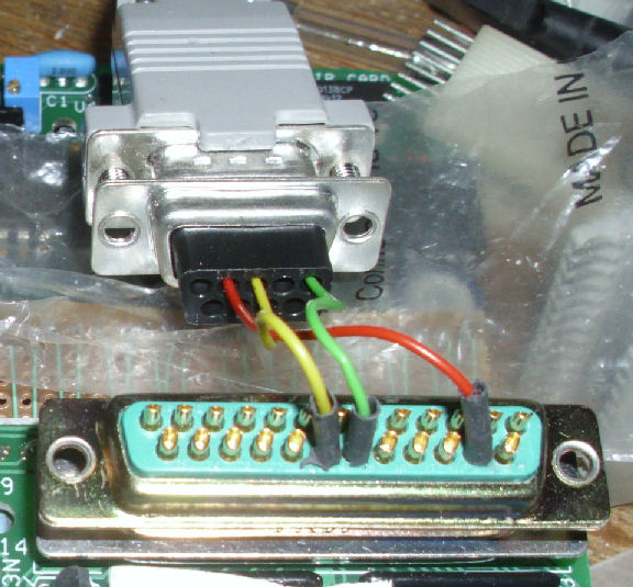
Recent versions of the 1802 M/S card have a power/TTL connector, which can be operated by a USB to TTL adapter. The 1802 M/S Front-Panel card, includes a DB-25 I/O connector, configured to connect to a classic IBM-PC parallel port. That cconnector also has pins dedicated to the serial interface. An old IBM-PC compatible, also has a DB-9 serial port. The photo on the left, shows a pair of connectors needed to make a simple DB-25 to DB-9 adapter for some versions of the 1802 M/S card.
If you get a "RS-232 to USB" adapter, it will expect to connect to a device with a "RS-232" connector, probably a DB-9. That device, was likely intended to be plugged into an old-skool IBM-PC compatible serial cable. The following describes how to provide the 1802 M/S card with that kind of connector, from the Card's DB-25 "parallel port" interface. See the IDIOT ROM monitor, ROM and RAM, and serial interface notes for more information - and your 1802 M/S card manual.
Here's an image of the 1802 Membership Card Front Panel at the DB-25 (25-pin) connector. You see a MALE DB-25 plugged into the Front Panel's "female" DB-25 connector. There are three wires from that connector, going to the back of a female DB-9 (9-pin) connector. That DB-9 is plugged into a "straight through" DB-9 cable to a PC laptop with a DB-9 serial interface. So the DB-9 I've wired up, "matches" the PC serial connection. OK? See the schematic above, but here's the wiring: DB25 pin 15 is TXD to DB-9 pin 2. DB25 pin 19 is GND to DB-9 pin 5. DB25 20 is RXD to DB-9 pin 3.
Rev I and later versions of the M/S card, have an additional connection at the power connector for TTL access to transmit and recieive. REv I and later, also support the DB-25 connection for "RS-232"; but they don't have the ability to change the "active" level of those signal. Refer to the Rev I or later manuals for details and options.
Many versions of the 1802 Membership Card, have an interface to support "RS-232" type connections. There's
circuits to accept and provide the higher-voltage signals used by RS-232; and to "invert" the logic if needed. If you want, you can build your own adapter for a more recent 1802 M/S card. Here's a document on a simple interface. It's based on the Rev G 1802 M/S card, here's that manual and schematic. The circuit shown uses ordinary transistors, not the ones on the Rev G with included resistors (RBT's) to save space. It's busy, but it generates a negative voltage for transmit. You can add another NPN transistor to "invert" logic, or use a LSTTL "gate" 74ALS00 or "inverter" 74ALS04 for the same purpose. It will still need 5V DC. - Herb
This page and edited content is copyright Herb Johnson (c) 2018. Contact Herb at www.retrotechnology.com, an email address is available on that page..