![[rev G CPU]](mem_revG_cpu_norom.jpg)
Last updated July 4 2017. Edited by Herb Johnson, (c) Herb Johnson, except for content written by Lee Hart and others. Contact Herb at www.retrotechnology.com, an email address is on that page.
This is the Rev G support Web page, with manuals, schematics, notes. As of Apr 23 2015, Rev G is not in distribution. Check the Membership Card "home page" for the current version and how to order.
Changes during distribution: Some Rev G kits shipped with Rev H CPU boards; there's a manual for that on this Web page. The CPU board addressing FET 2N7000 was changed to a FJN3301 NPN transistor and there's a resistor change. It's recommended that you change the resistor and change the FET to the FNJ3301. Also, some Rev G kits were distributed with LEDs with modified leads. Read these Error and Fixes notes for details and fixes, and other technical notes. - Herb Johnson
![[rev G assembled]](mem_revG_assem_thomas.jpg)
"For those just tuning in, the Membership Card is a reproduction of the original Popular Electronics COSMAC Elf computer, but shrunk to fit in an Altoids tin! It works the same, and runs the same software." - Lee Hart, developer. The Membership card home Web page has links to previous versions, history, testing, hardware notes and software - and HOW TO ORDER. This page has information specific to the Rev G card. For links to previous revisions, go to the Membership card home Web page.
The photo on the left is of the assembled Rev G CPU board, less ROM. On the right, is an assembled
Rev G. Both photos courtesy of Mark Thomas, who assembled these in June 2014.
![[empty boards]](mship_revgbd1.jpg)
![[parts kit]](mship_revH_pre_cpu.jpg)
Documentation: The Rev G manual is a .PDF file at this link. dated Mar 27 2015 w/Apr 8 schematic.
Here's the link to the Rev G schematic .PDF dated April 8 2015.
Here's the link to the Rev G boards layout .PDF dated Jan 22 2014.
This is the link to the pre-production manual for Rev H CPU and Rev G front panel with schematic. dated Apr 7 2015, with schematic Mar 27 2015
<<--- An image of the pre-production Rev H CPU board is on the left.
Pre-April 2015, the Rev G CPU board used a FET 2N7000 for Q1, and R5 was 100K. See error "FET enable" for details.
.
Here's a compact Membership Card and 1802 operating guide PDF dated Feb 18 2014.
![[parts kit]](mship_revfparts1.jpg) On the left is a Rev F kit parts from Jan 2014; the Rev G parts kit looks very much the same. The unpopulated Rev G boards of Feb 2014 are shown on the right. The front cover board at the top is offered separately from the logic boards below it. Rev G product descriptions are below.
On the left is a Rev F kit parts from Jan 2014; the Rev G parts kit looks very much the same. The unpopulated Rev G boards of Feb 2014 are shown on the right. The front cover board at the top is offered separately from the logic boards below it. Rev G product descriptions are below.
In the news: April 2015 The 1802 Membership Card was shown and sold at Vintage Computer Festival - East 10.0 in central New Jersey USA, during the April 18th weekend. There were dozens of vintage computing exhibits, and a 50th anniversary series of PDP-8 exhibits including a newly-restored PDP-8 "straight 8" from the early 1970's.
In the news:The March 2015 issue of IEEE Spectrum magazine, an academic-oriented publication for electrical engineers, has an article on the 1802 Membership Card. "...Here Comes the COSMAC Elf" features some mention of ELF history, features of the 1802 and the Membership Card, and links to this site, cosmacelf.com and Lee Hart's sales site.
Refer to the Membership Card home page for the ordering Web link. An email contact address is there for special orders. - Herb Johnson
Initial testing and programming
Rev G description
Rev G features and options, "upgrades" for previous revisions
Order the Membership Card from the home page
Engineering Data
Hardware and software and notes about them
Errors and corrections
Chronology of Membership Card products & support Web pages
The kit manual has test programs and debug information. Also, see this document on Testing the 1802 Membership Card with small toggle-in programs. Basic operations of the front panel are described.
There's more links about testing and use, under "features" on this Web page. That includes links
about adapting previous versions of the M/S card to Rev G - like features. Other links are to testing hardware Web pages and testing software Web pages are on listed on the home Web page. - Herb Johnson
The Rev G Membership cards consist of a CPU board stacked on a Front Panel board. You can also buy a Cover Board, "a circuit board to cover the switches and lights of the Front Panel card.
![[rev G CPU]](mship_revgcpubd.jpg)
![[rev G CPU]](mem_revG_cpu_edge.jpg)
- 1802 microprocessor (option for 1804/5/6 without load mode). - 2k-32k memory chip .6-inch socket; accepts 6116 2k RAM 6264 8k RAM 62256 32k RAM 2716 2k EPROM 2732 4k EPROM 2764 8k EPROM 27128 16k EPROM 27256 32k EPROM (or equivalents) - .3-inch RAM DIP socket under .6-inch socket. (Photo on left, courtesy of Mark Thomas, June 2014.) Accepts Cypress CY7C199 32k X8 RAM and compatible 300 mill wide 28-pin bytewide RAM - supercapacitor to maintain RAM contents with power off - one 8-bit output port (OUT4 default, or you can jumper-select others) - output port multiplexed to four DB-25 pins (PC parallel port) - OR all 8 bits out to eight DB-25 pins (jumper selected) - one 8-bit input port (INP4 default or you can jumper-select others) - jumper select on board ROM/RAM for high or low 32K address space - optional +5 volt power input at DB-25 pin 18 w/diode protection (jumper selected) - ceramic resonator for stable clock (replaces R/C in early versions) - clock adjustable with pot (slow for low power, fast for high speed) - the usual 1802 I/O bits (Q, EF1-EF4, INT, etc.) - all I/O and power brought out to a 30-pin header - size: 3.5" x 2.125" - power: 3-6vdc at 1ma (plus whatever the memory chip chosen requires)
![[rev G front panel]](mship_revgfrontbd.jpg)
![[rev G front panel]](mship_revgfrontasm.jpg)
- plugs onto the 30-pin connector of the Membership Card (assembled photo by Lee Hart)
- provides the Elf front panel interface and "classic PC" DB-25 parallel interface,
- optional serial interface with LED activity, software bit-driven from EF3 and Q, active high/low selectable
- 8 data output LEDs (memory reads and OUT4)
- 1 Q output LED
- 8 data input toggle switches (memory writes and INP4)
- read/write memory, run/clear, run/load toggle switches
- 1 input and EF4 pushbutton
- "stand alone" memory read, write, program load, and run operations
- no PC, external hardware, or any onboard program, are required for front-panel use.
- size: 3.5" x 2.125"
- power: adds about 3ma for each LED lit
DB-25 PC parallel port connector on Front Panel:
- has all I/O and control signals to classic PC parallel port (8 bits in, 4 out)
- allow full front panel operation by "classic" PC (software discusssed) or a microcontroller (Arduino, etc.)
- builder can jumper to bring out all 8 bits and bring in +5 on DB-25
- optional: selected pins for hardware serial in and out
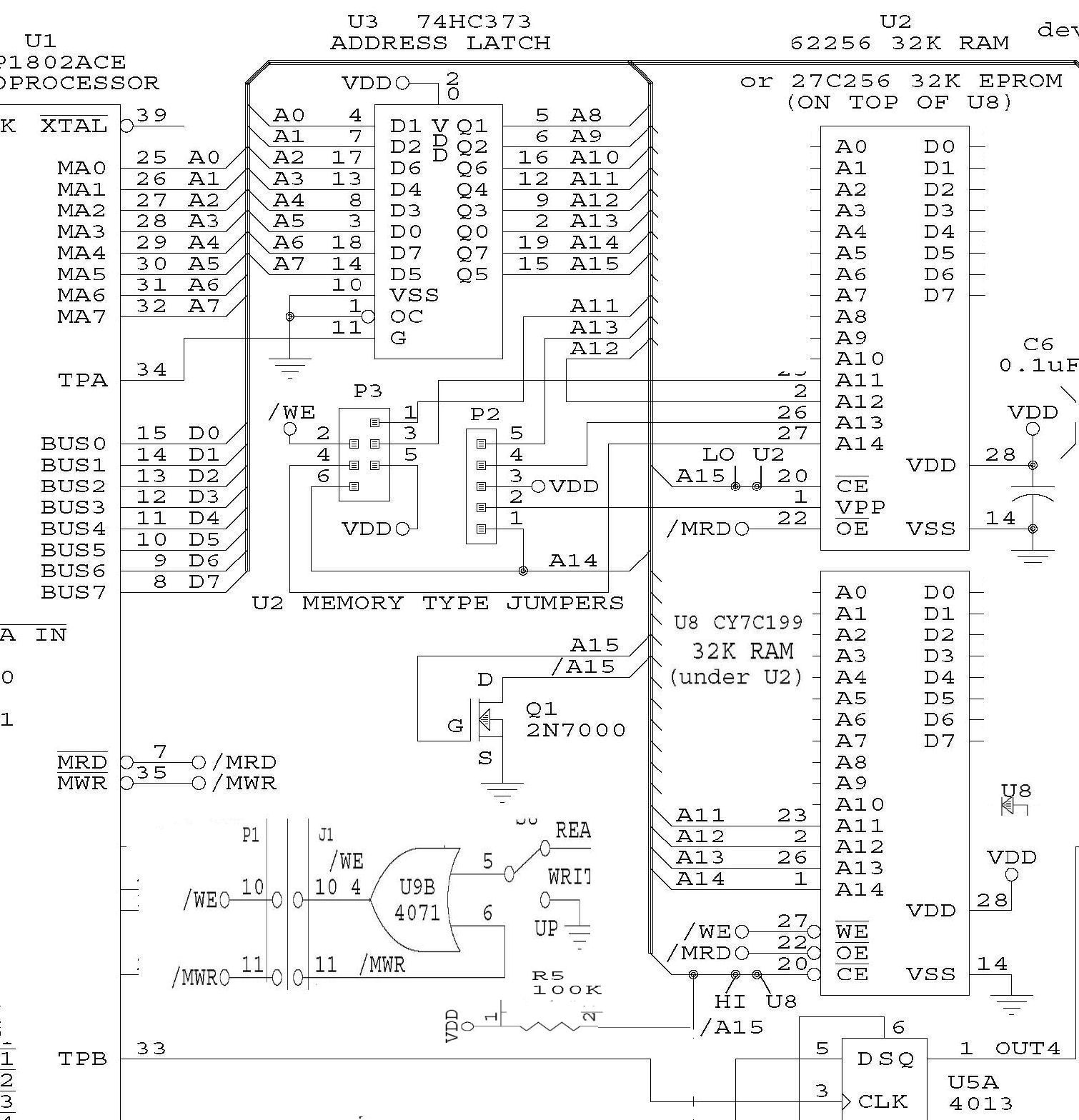
Here's a link to the Rev G schematic of the logic cards.
![[panel cover]](mship_revgpanbd.jpg)
The Membership Card Cover Board is a PC board to cover the Altoids lid and mounts on the Front Panel board. The board has holes for the switches and lights, power, and DB-25 connector. There's silkscreened labels and a tinned copper shield on the back. Cut a large rough rectangular hole in the Altoids box, and solder or epoxy this board to the top to provide a neat finished front panel.
Small size, common components, assembly manual for hands-on building The front panel and CPU boards stack, and will fit in an Altoids tin. The front panel cover board (optional) fits over the Altoids lid. Only common readily available electronic parts are used (the 1802 is the hardest part to get). All thru-hole parts, for easy assembly (no surface mount). Assembly manual guides construction part by part, with testing and debug information.
stable clock frequency with ceramic resonator AND variable clock with trimpot This has been a feature since Rev F. A ceramic resonator and also RAM/ROM can be added (with effort) to various older revision cards, see this Tech Note.
Standby mode, nonvolitile RAM: Seperating the CPU board from the Front Panel will put the CPU board into a "standby state", program halted and RAM powered by the supercapacitor. Removing the power connector disconnects the rest of the "stack" from supercap power to the RAM and processor. Retains RAM content for some time, longer for CMOS RAM.
optional RAM and ROM on one CPU board A .3-inch wide RAM chip can be installed under the .6-inch wide ROM chip to support a ROM/RAM based monitor. See the 1802 "IDIOT" ROM monitor Web page for an example ROM monitor. See the 1802 "IDIOT" ROM, RAM, serial upgrade Web page for details about this option. Stacking of ROM and RAM for Rev F as a manual change is discussed on this linked Web page. It may be informative for Rev G use.
load/run and data transfer via "parallel port" The front-panel has a DB-25 connector that compliments the traditional "PC parallel port". Old-school PC's under MS-DOS can run programs in QBASIC to download and run Membership Card programs; the Windows OS limits that capability and modern Windows computers lack the parallel port. So some M/S card owners have built microcontrollers to operate the Membership Card. See this Note about use of the parallel port by old PC's, with links to examples of use of microcontrollers.
optional serial interface operation It has an RS-232 or TTL serial interface via EF3 and Q. The TXD transmit output, can generate a negative signal level for improved RS-232 operation. The Q LED now also shows serial activity. The interface can be constructed for for inverted or non-inverted serial in and out, as documented in the kit manual. The EPROM could contain software drivers to use a PC's RS-232 serial port, or USB port through a suitable serial-to-USB adapter. A "kit" with serial connector, IDIOT monitor ROM and RAM and specific instructions, is described on this linked Web page. A more general and technically detailed discussion of the serial interface and operation of a ROM monitor is on this linked Web page. Mark Thomas, who developed these same features on an earlier-revision M/S card, noted: "I like that my revG membership card with its capacitor-diode trick to pull the RS-232 output to -V, works just great as-is with the RS232 port on my DEC video terminal."
optional stacking of CPU boards for dual ROM/RAM operation, four I/O ports Two CPU boards can be stacked by using a CPU socket to connect the two boards. One of them is has the CPU chips and either ROM or RAM; the other is driven by the CPU and used to hold ROM or RAM; and provide another pair of input and output ports at another address. Here's a Tech Note about stacking two Rev D or later Membership Card CPU boards. The details are not complete, and the Note is written to support a range of CPU board revisions. There's a description on how to change the CPU board's I/O port addressing.
Refer to the Membership Card home page for the current ordering status of the Rev G kit. An email address adn Web link takes you to the developer for ordering and contact.
Dimensions of assembled Rev G, preliminary, Feb 24 2014, Lee Hart : "Though it's very close, the height [of the stacked boards] is a bit too thick to get the Altoids case to close. Not using socket pins for U8 (the .3-inch-wide RAM) would help; maybe enough. I'll have to build one that way and see." - Lee Hart
Rev F & G Power consumption by RAM choice, changes to RAM addressing - Lee Hart Feb 2014
1. Rev.F at 5v, 1.782 MHz, U2 =  Hitachi HM62256 32k RAM, U8 = none,
   Q1 shortens U2 chip-select time to 1 clock cycle. Running program
   3 in the manual (echo the switch settings in LEDs; all LEDs off):
   Icc = 4.22ma

2. Rev.G, same conditions:  Icc = 7.40ma

3. Rev.G, same but U8 = .3-inch-wide Cypress CY7C199 32k RAM (not used by program)
   Icc = 7.41ma        so not accessing U8 does not affect power

4. Rev.G, same as 3 but using U8 RAM
   Icc = 46.4ma        so accessing U8 increases power about 6:1

5. same as 4, using WAIT to stop program at various points:
   Icc = 4.78ma if it stops when U8 is *not* chip selected,
   Icc = 28.31ma if it stops when U8 *is* chip-selected.
Conclusions: - Power consumption increased slightly (with Hitachi HM62256 CMOS RAM) by chip-selecting U2 for an entire 8 clock cycles instead of just 1. - Cypress CY7C199 increases power consumption about 6:1 when active. Has no effect when not active. It apparently draws a high "access" current (~100ma) when first chip-selected, which drops to a lower "hold" current (~25ma) when chip selected but all inputs are not changing.- Lee Hart
CMOS .3-inch RAM: Lee Hart, Mar 1 2014: "I discovered Hitachi also made the HM62256 (CMOS 32K x 8 RAM) in a 0.3" wide DIP.. The 62256 is a true CMOS RAM, and so has a low supply current -- essentially zero when static, even if chip-select is held low. It is about 1/10th as fast, and about 1/10th the operating power of the Cypress CY7C199. "
"The [relevant] Hitachi part number is HM62256ASP, HM62256ALSP, HM62256BSP or HM62256BLSP. A "speed" number follows this, but any speed works in the Membership Card. Suffixes [mean:] A or B is new, P means it is a plastic DIP, S means "skinny" 0.3" wide DIP, L is selected for lower supply current... They are out of production [but may be surplus]."
Schottky diode: D12 on the front panel board, is a Schottky diode 1N5818. It's in series with optional DC power as a protection diode. That kind of diode has a low forward voltage drop; at tens of milliamps it's a .2V drop. Ordinary silicon diodes have a .6V drop. The choice of a Schottky diode is just another Lee Hart way to reduce power consumption. - Herb
More hardware notes: Here's a link to some earlier engineering notes about power consumption, program retention, current consumption of LED's by color. There's also more information in the docs for previous versions.
The Rev G uses "resistor biased transistors" for the serial interface. A Tech Note about transistors with internal resistors, used on the M/S card serial I/O. Here's the data sheet for the FJN3307 NPN and Here's the data sheet for the FJN4303 PNP
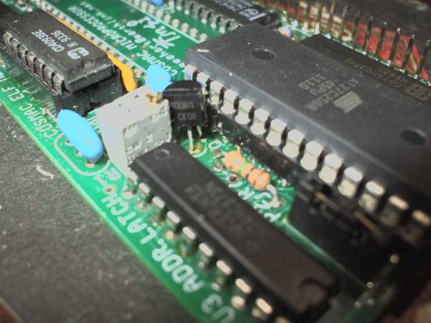
![[blue LEDs]](revg_blue_board.jpg)
This Web site has dozens of Web pages about hardware, software, operation and upgrades and debugging of the Membership Card. Please, please look at the Home Page of the 1802 Membership Card for links to those notes. Collections of hardware note Web links and software note Web links are on these linked pages.
In June 2014, David Kriest assembled a Rev G CPU card as a stop-motion video. See the video on Youtube as "MC Revg" by "Corecoder" for June 13 2014.
Herb Johnson built a Rev G with *blue* LED's in Feb 2015. "The R11 SIP resistors had to be increased from 1K to 4.7K because blue LED's are brighter. One of the SIP resistors (pin 3) is used for the Q LED; that should be bypassed with a 1K resistor. Result? Each blue LED consumes .75ma to 1ma current. LED voltage drop measures 2.7V. The two boards consume about 12ma to 16mA at 4 - 5V Vcc, when running a ROM program at 2MHz. This includes a narrow RAM, and operation of the bicolor Q & EF3 LED through the RS-232 "inverting" interface. - Herb
There was a design change during distribution of the Rev G 1802 Membership Card, of parts for the CPU board. The FET 2N7000 used to select addressing in Rev G, was changed to a "resistor biased" NPN transistor FJN3301R. In addition, the resistor SIP R5 was reduced to 10K from 100K; or a collector resistor to +5V of 10K added instead of changing the SIP. Why? The A15 signal produced by the FET, was not reliable. If you want the details, or just how-to on the fix, read this Tech Note about the problem, diagnosis, and various fixes.
If your Rev G has the FET 2N7000, consider these changes. The most-current Rev G manual shows the replaced parts and installation of them. The Rev H and later CPU boards incorporate this change or use other components.
Simple description of changes: read this Tech Note for for details.
Summary: 1) change the 100K pullup resistor for /A15 to 10K (or 1K). 2) You can optionally change the FET 2N7000 to a "resistor biased transistor" FJN3301R. These will speed up /A15.
1a) EITHER replace R5 SIP: Change the R5 SIP from 100K to a 10K SIP resistor pack; it will slighly increase current consumption. The R5 SIP is the skinny black component with nine pins, between the 1802 CPU and the 4093 IC. Check the Rev G manual for more information.
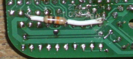
1b) OR add a pullup resistor: decrease the FET 2N7000 pullup resistor to 10K, in parallel with the 100K value in the R5 SIP resistor pack. For faster operation (say a 4Mhz CPU clock) but more current, use a 1K resistor. A "field" fix is to solder-in an add-on 10K resistor, from the FET drain pin, to Vcc on P2 pin 3, on the back of the CPU board. Lee Hart suggests an alternative placement on the IC side from the HI hole to a Vcc hole near D10 & R6.
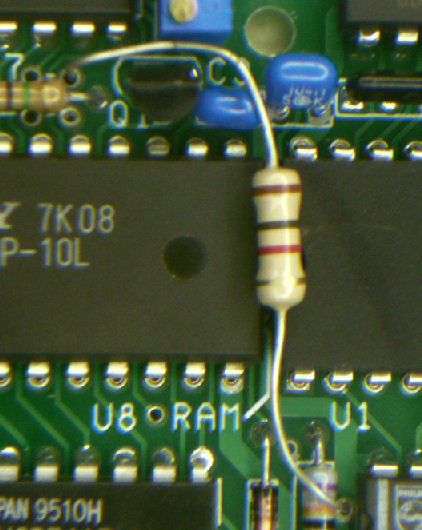
OPTIONALLY 2) replace FET 2N7000 with FJN3301R: This photo shows the placement of the FJN3301R in Q1 location. (the R5 SIP is yellow and already changed from 100K.) Notice the transistor body is rotated about 45 degrees to properly align with the Q1 thru holes. The most recent Rev G manual (ans the Tech Note mentioned here) describe installation in detail.
March 30th 2015:[In the course of ordering and distibuting parts for a recent run of Rev G kits,] one builder alerted me that his red LEDs (D0-D7) needed to be installed *backwards* to work. What the heck?!?
It turned out that the new LEDs I ordered (from the same source, same part#) have the flat side on the case on the OPPOSITE side from all the previous ones. The long lead is still +, and the short lead is still -. So install them by the lead length, NOT the flat side! If you install them with the flat side matching the board the way the manual says, the new ones won't work. You'll have to remove them, and turn them around! What's worse; I just dumped the new LEDs into the bin with my remaining LEDs. That means you may have a mix; old and new. So if you received a Membership Card kit recently, please *check* your LEDs before installing them. If you need replacements, contact me directly and I'll send them out for free. I apologize for this. I was in a hurry to get the orders out, and missed it. But in this case, it's the same part# I've been buying for years, and the data sheet says the flat is next to the cathode. These are clearly a QC defect. - Lee Hart
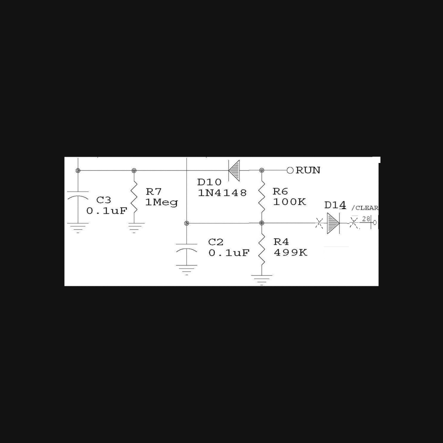
April 2015: Lee Hart determined that a 1N4148 diode on the /CLEAR line would be useful "so you get a power-on-reset even if the Front Panel [is connected and] switches are set to RUN" when powered up. "With an EPROM installed in U2, and *no* front panel connected, the board powers up, resets itself, and then runs the program correctly. But if the front panel IS connected, I have to *manually* reset it with the switches, or it wakes up "insane"." Here's how to add that diode. "1) On the CPU board, cut the trace to P1 pin 28 (/CLEAR). 2) D14 cathode goes to that pin. 3) D14 anode goes to the other side of this cut trace (to C2, 1802 /CLEAR pin 3, and R6)."Here's a schematic fragment of the change.
The Rev H and later CPU boards incorporate this change.
Lee: "An interesting quirk: Q=1 lights the red LED, and EF3=1 lights the green LED. So you would think that both would light in this loop test, and you'd see yellow. But both LEDs share the same series resistor, and the green LED has a higher forward voltage drop. This means you don't see the green LED; D8 just lights up red. To see green, you can [disconnect your serial external connections and] jumper DB25 pin 20 to power or ground while Q=0."
"When you are feeding in TTL or RS-232 data whose high-state voltage is greater than the Membership Card's supply, then the green does light even if the red is lit."
"You can also enter a trivial program to check EF3, and set Q to the opposite state. Then the LED lights either red or green, depending on the logic level at RXD (DB25 pin 20). This proves that both EF3 and Q and the LED circuits all work." - Lee Hart
Herb: Added to the M/S simple test programs is that "trivial" program to read EF3 and write to Q. It's useful as a "software loopback" to verify your serial hardware and your terminal (program) operation. There's two programs, one inverts the result and one does not. One of them has gotta work...... - Herb
Herb Johnson: I've found that maximum speed for the M/S card seems to be "set" in a stable manner, by rotating the trimpot fully counter-clockwise (CCW), until it "clicks" - note that rotational position. Then rotate the trimpot clockwise, "about" half a turn but *no more than one turn*. ( the manual says 3/4 clockwise.) It may not be well-stated, but both the IDIOT monitor and the ELF2K monitor, "want" the clock set to maximum (ceramic resonator labled) speed.
An oscilloscope to monitor the clock at CPU pin 1, shows how the clock speed quickly declines once the trimpot is turned more than "about" one turn from maximum clock speed. But the clock is a little "mushy" at the very maximum CCW setting, and a little more "square" when backed off roughly as described. - Herb
Apr 2015: Rev H in pre-production. /A15 FET 2N7000 changed to transistor and pullups changed to 10K, to improve rise-time. Diode on /CLEAR to force on power-up without regard to front-panel state.
Feb 2014: Rev G in production. Adds optional narrow RAM to sit under .6-inch wide ROM and optional hardware for serial interface.
May 2013: Rev F in production. 1.8 MHz ceramic resonator replaces cap C1 in clock circuit. Here's the Rev F support page.
Earlier design and production by date is now on a history of production Web page. Previous version support pages will also use that document. But check this page for changes about use and design of Rev G.
2005-2009 development history: See the Membership Card development page for years of discussion about the present Membership Card design, and the philosophy behind it.
30 years ago, Lee developed an 1802 single board computer called BASYS. Look at the BASYS manual for hardware interface suggestions for the Membership Card.
This page and edited content is copyright Herb Johnson (c) 2017. Contact Herb at www.retrotechnology.com, an email address is available on that page..