![[Rev C with ceramic resonator]](ctog_fets_1.jpg)
Last updated May 4 2014. Edited by Herb Johnson, (c) Herb Johnson, except for content written by others.
This is one of a series of Tech Notes to support the 1802 Membership Card. Follow that Web link for current status of that product and links to the current support and sales Web pages.
The Rev G 1802 Membership Card CPU board, continues the Rev F feature of a ceramic resonator as part of the clock. Earlier revs used an R/C circuit. Rev G also has a RAM/ROM combination; earlier revs only support RAM or ROM, using a FET to invert (or not) A15. In a previous Tech Note, I and Thomas rebuilt a Rev F CPU board to support both RAM and ROM.
On April 2014 I built an 1802 Membership Card Rev C CPU board, to include Rev G features of 2.0Mhz ceramic resonator and two-FET selection between ROM and RAM. .3-inch "narrow" RAM was installed under the CPU board; another had a .6-inch wide RAM underneath. This work shows the work, and issues and problems involved. Also refer to the Rev F rebuild Tech Note menitoned above for more details. - Herb Johnson
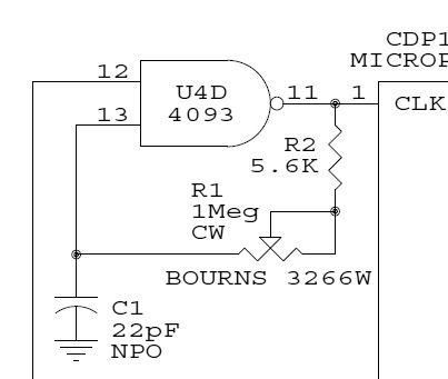
![[mods for resonator]](ctog_reson_1.jpg) Rev C R-C clock circuit
Rev C R-C clock circuit
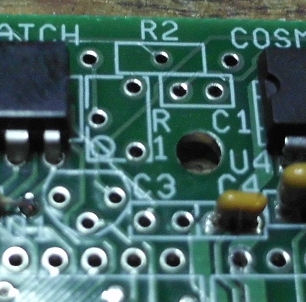
Rev C R-C PC board layoutC1, R2, and R1 trimpot
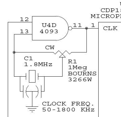
Rev F, G ceramic resonator circuit
Rev F, G ceramic resonator board layout
sketch for modsResonator fits in the C1 holes, one pin tied to R1 trimpot.
Other side of trimpot wired to end of R2. short at end of trimpot cut. Wires to pins 11 and 13 of IC U4.
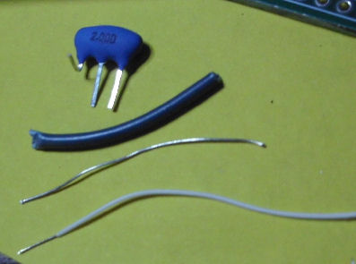
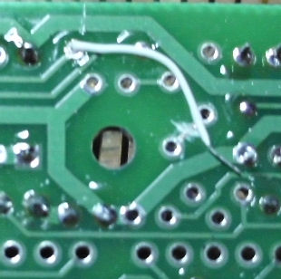
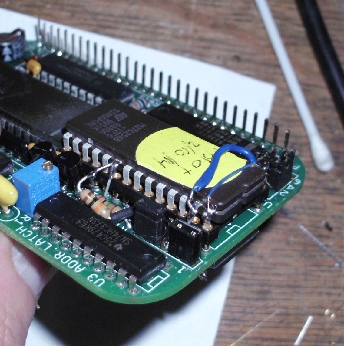
![[mods for resonator]](ctog_reson_3.jpg)
resonator with pin bent for wire, wires and insulator for bare lead of resonator
resonator soldered in for C1, insulated lead to hole formerly for R2
wire under board will be soldered to trimpot lead, trace cut between trimpot leads
another view of resonator after FET and other parts (except trimpot) installed
Trimpot and C3 not installed to make space to install 2nd FET.
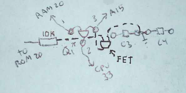
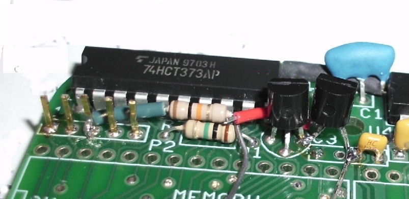
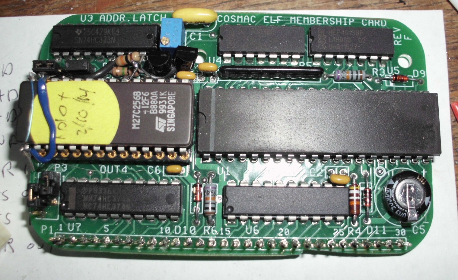
![[Rev C with ceramic resonator]](ctog_fets_4.jpg)
sketch schematic for 2nd FET and resistor to wire to ROM pin 20Also shows ROM rewiring
board layout sketch to add 2nd FET and resistor
First FET and R3 installed as normal. C3 installed slightly elevated. C4 and R1 trimpot not installed until later to make space.
Install the 100K resistor, one lead insulated and installed to base of pin 3 of P2 (+5v). Other end open
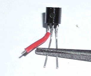
2nd FET, one lead insulated insulation stripped from wire
2nd FET installed, soldered between C3 and C4 and to pin 3 of first fet
insulation on remaining lead soldered to loose resistor.
top view of both FETs and other components
excess lead will go to ROM pin 20? to select "other" 32K address space versus RAM.
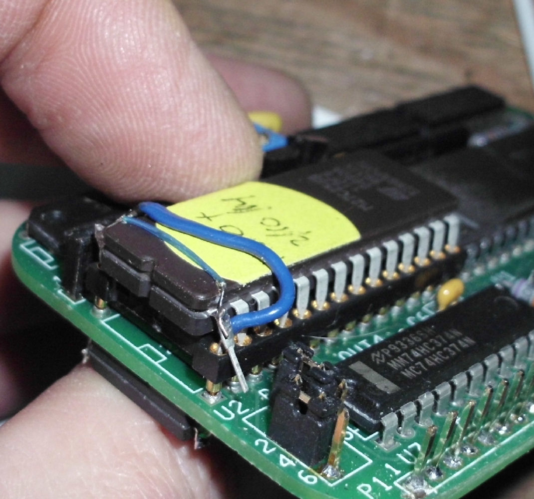
![[ROM rewired]](ctog_rom_strap1.jpg)
Note: the following photos are a Rev F board with its ROM wired up.
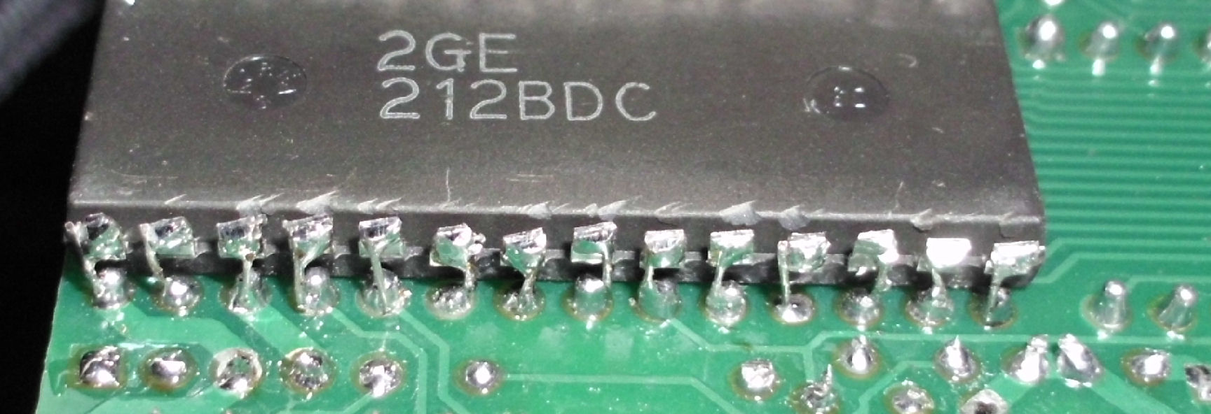
![[ROM rewired]](ctog_rom_fet.jpg) The CPU board is strapped to accept RAM, so the ROM must be wired differently.
The CPU board is strapped to accept RAM, so the ROM must be wired differently.
Pull ROM pin 1 from socket pin 1, wire ROM pin 1 to pin 28 to pull pin 1 high.
Pull pin from socket on pin 27, wired to inserted in socket pin 1.
And ROM pin 20 is pulled from socket and wired to FET to select ROM
ROM strap end view see ROM pins not in socket pins. Also RAM under board.
ROM strap view see wires to 20, 27, 28 on ROM
ROM strap view see wire soldered to ROM pin 1, and 2nd wire inserted in socket pin 1
ROM strap view view from above
The Rev G CPU board, hides a .3-inch wide RAM under the .6-inch wide ROM. There's board pins for both. Also the Rev G uses one FET, to invert A15, so ROM and RAM are each in a 32K byte address space.
For Rev F and earlier including Rev C, there's three choices about where to put the physical RAM with ROM.
Solder ROM over RAM. You install the .6-inch wide RAM in the CPU board socket, and solder the ROM atop it. Most of the RAM pins are soldered to the ROM, except for the ROM pins as described above. This kind of committs both ROM and RAM; it's hard to take them apart again. But it's simple to do. YOu also have to have enough length on the CPU 30-pin connector pins, so the extra height of the ROM/RAM stack can be accomodated. I haven't done this yet, I tried other arrangments.
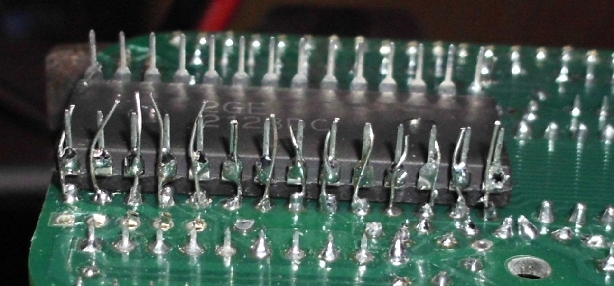
Solder wide RAM under CPU board. Or, you wire-up the .6-inch wide RAM under the CPU board RAM socket and upside down. It's pretty painful to wire it underneath. The pins have to be cut off and you have to solder tiny wires "up" from the pins. This is what I did as in the photos above and detailed below. I had to resolder some pins a few times to get proper connections. But, you can remove and replace the ROM "relatively" easily, except for pins soldered up or inserted in the socket.
Soldered RAM pins with tiny wires
RAM pins cut off
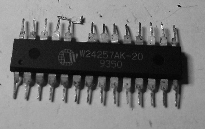
Solder narrow RAM under CPU board.A third choice, is to use a .3-inch wide RAM, and bend the pins backwards to make contact with the socket pins under the socket, and solder those. Good idea in principle. You don't have to change the height of the CPU board pins, but the "stack" is still taller with the RAM under the CPU board.
But my experience is, that some brands of narrow RAM have poorly-embedded pins - they will pop out if bent that way. Turns out to depend on how the pins were constructed, and that seems to varies by brand and model of RAM chip. I lost two chips from one brand, but the first of another was OK.
broken pin from bent .3-wide RAM
another brand, bent OK and soldered
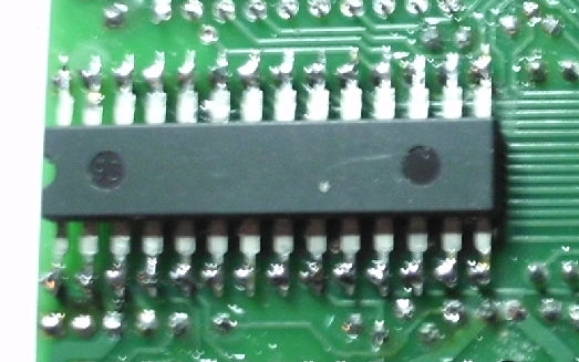
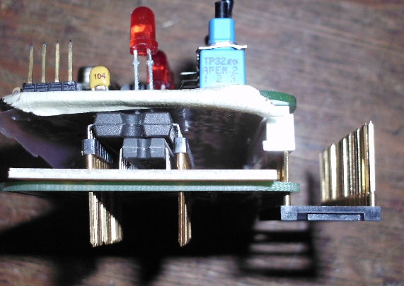
Here's the stack with Rev C CPU, .3 wide RAM, no ROM (that's the 1802 you see) and long 30-pin header
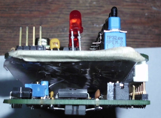
Or....? There may be other "dodges" or ways to jam in a RAM. Maybe you can put a long-pin socket in the CPU board and solder a narrow or wide RAM under the socket and THEN solder the socket on the CPU board. Or solder a narrow RAM to a tiny PC board, put that under the ROM's socket. Here's a photo of how that might look, note the (faked) extra-long 30-pin header on the CPU board. But Lee Hart redesigned the CPU board in Rev G, to make the best accomodation for both ROM and RAM, and that's the most straightforward solution.
Herb Johnson
This page and edited content is copyright Herb Johnson (c) 2014. Contact Herb at www.retrotechnology.com, an email address is available on that page..