![[ROM stack schematic]](mem_romstack_cpu.jpg)
Last updated May 30 2016. Edited by Herb Johnson, (c) Herb Johnson, except for content written by Mark Thomas, Lee Hart and others. Some content from discussions in cosmacelf and in email by Mark Thomas, Lee Hart, Sept-Oct 2013, with perimission.
This page references hardware for Lee Hart's COSMAC 1802 "Membership Card". Here's a link to the home Web page for the "Membership Card" It has history, development, current status, and links to other documents. There's a link there to the Web page for the current available version of the Membership Card kit, and a link on how to order it.
in later 2013, Mark Thomas posted a question in the Yahoo group cosmacelf, "how to add a ROM monitor and serial interface to the Membership Card?" Lee Hart responded with some options, and Mark went with his idea of a piggy-back ROM and got it to work. Then I built up a Rev F Membership Card, and got it to work as well. These are edited notes and photos. A companion Web page describes serial interface options. Also, Rev G of the M/S card, released Feb 2014, provides a RAM under the ROM, and a serial interface. While these notes are primarily for Rev F and earlier M/S cards, they are informative for Rev G use of those features. - Herb Johnson
Sept 15th 2013, Mark posted: "So, I'm putting together a membership card in a slightly larger case than an altoids tin, and I got to thinking it sure would be nice if it had a ROM monitor, and I could put a serial port on my enclosure. Could I piggy back an elf2k ROM with the RAM chip, do something with pin 20 to select the ROM for 0x8000? Are there any other issues that might prevent me from using a membership card with an elf2k ROM? Has anyone else done similarly? - Mark
Lee's response: "There are several ways you can do this.
1. You can load a program into RAM, and maintain power to keep it there. Or, 2. Same thing, but use a nonvolatile RAM, like one with a piggyback lithium cell, or a ferroelectric RAM [FRAM]. This way you don't need to maintain power.
3. You can build an external PROM board, as designed by Richard or Herb Johnson. These are basically a binary counter to provide sequential addresses to a PROM or EPROM. Plug it in to the 25-pin front socket, and its contents are automatically [or programmatically] loaded into RAM.
4. Get a 2nd Membership Card (rev.D or later). There are provisions to stack the two [CPU boards], with a ROM on one board and a RAM on the other board. Now you have both ROM and RAM, as well as a second I/O port.
5. I'm sure there are other ways as well. I can imagine piggy-backing two memory chips (one EPROM, one RAM), with one of the address lines used to chip-select between the two". - Lee Hart.
Mark chose the "piggy-back" method of a PROM on top of a RAM chip. Here's Lee Hart's discussion on how to do that. [Herb's edits are in []'s].
Hi Mark: Look at this portion of the schematic in the Membership Card manual. You can read in the Membership Card manual page 9 there are two ways to install transistor Q1. One way addresses the memory chip from 0-32k; the other way addresses it from 32k-64k. [So you'll need to add a second transistor to get two addresses.]
What you also want to do is solder a 28-pin IC socket on top of your 32k RAM chip. Leave the RAM chip's pins clear, so it can still plug into the socket on the Membership Card.
All pins of the ROM socket solder to the RAM pins EXCEPT pins 1, 20, and 27. Install the jumpers at P2 and P3 for the bottom memory chip (the RAM). Install Q1 [on the PC board as usual] to address the RAM at 32k-64k.
Now, you'll have to hand-wire pins 1, 20, and 27 of the EPROM socket
as described [later] for the jumper options for your [size of]
EPROM (27C256 if it's a 32k part). You will also need a second
Q1 transistor and pull-up resistor. Wire that to
chip-select the EPROM from 0-32k. - Lee Hart
Some days later, Mark Thomas discussed and posted to cosmacelf, photos of his ROM as stacked on the RAM of the M/S card, without a socket. Months later in early 2014, I replicated his work. This Web page shows work from both. NOTE: Both address the RAM at 0000H and the ROM at 8000H; the added FET provides the ROM addressing. To run the ROM you have to toggle in a jump at the start of RAM: C0 80 00 is a JMP 8000H. ROM code must be assembled to run at 8000H and programmed into the ROM at the "bottom" of its addressing.
Mark writes: "Sorry the attached schematics are rough and hand-drawn. I am extremely appreciative of the guidance Lee provided on the wiring."
![[ROM stack schematic]](mem_romstack_rom.jpg)
Here's a VERY rough schematic for the ROM stack.
Parts: 1x AT27C256R-45PU OTP ROM (elf2k v88, see below)
1x MOSFET, N-channel 2N7000 (Jameco 119423, same as original Q1)
1x 100k 1/8W resistor
I carefully bent back pins 1, 20, & 27 on the ROM. Then I soldered all
the remaining pins in parallel with the corresponding RAM pins.
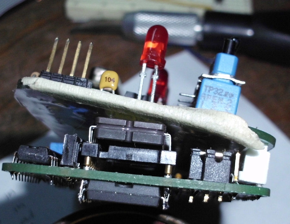
![[photo 6]](membcard2k-6.jpg)
![[photo 7]](membcard2k-7.jpg)
ROM pin #1 needs VDD, which I wired to nearby pin #28.
ROM pin #27 needs to go to A14, available on P3 pin #6.
ROM pin #20 goes to the drain of the additional transistor, and a 100k pull-up.
![[FET wriring]](membcard2k-8.jpg)
The second FET to the ROM enable, is wired as follows:
The gate goes to the FET pin 3, that's A15.
The source goes to FET pin 4, that's ground.
The drain output goes to ROM pin #20 as described above, selecting the ROM
when A15 is high for addresses at 8000H and above.
![[photo of FET & ROM wiring]](membcard2k-9.jpg)
![[photo of FET & ROM wiring]](membcard2k-10.jpg)
The board is jumpered for 32K of RAM as follows:
P2 1-2, 4-5
P3 1-3, 2-4
note that P3 pin 6 or A14 goes to the ROM.
You have to toggle in a jump at the start of RAM to run the ROM: C0 80 00.
In Jan 2014, Mark added: "Soldering the piggy back chip was the easy part, for me. Wedging the transistor in next to the other, and getting the wires right, required more care, in my opinion. If you ever were making an update to that board, and included pads for the pair of transistors and the extra lines towards the ROM, that gets us most of the way there, with no surface mount or daughter card involved.". -- Mark G. Thomas
Mark's photos of his ROM and card are also on the cosmacelf Yahoo site under the photo albums. Or look for the Yahoo cosmacelf Web page, and select Photo Albums > Mark Thomas' Membership Card-2k.
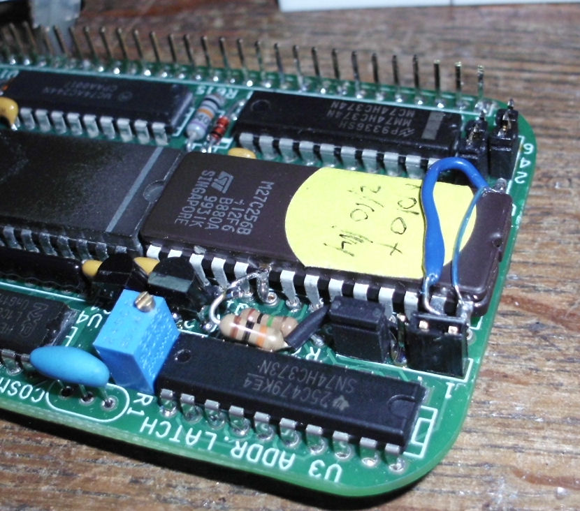
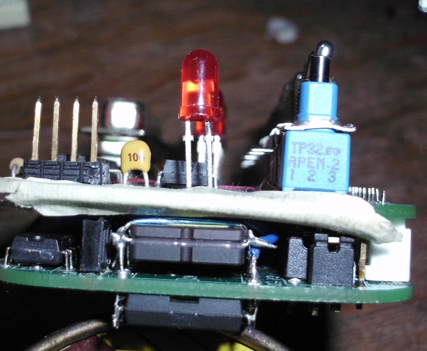
In Jan-Feb 2014, I built a Rev F CPU board to modify it for a ROM stacked on RAM. My RAM was mounted under the CPU board, which was difficult but successful; and a second FET was added to address the ROM. The first FET and the CPU board was set up to address 32Kbytes of RAM at 0000H, so the second FET inverted the first to address 8000H and up, to the ROM. I also built a serial interface, and an extender card between the CPU and front panel board. Read the linked Web page for details. - Herb
I put in a second ROM socket because it's difficult to align the ROM's pins into the tiny board-mounted socket pins.
but the "stack" was too tall and not stable. Once I
was confident in the ROM's content, I removed the ROM socket and used in-board socket pins to lower the ROM's height. The ROM is shown mounted on the socket pins and The CPU board height is lower as a result.
Mark Thomas used an Elf2k ROM on his Rev F M/S card, as he describes here:
I installed an Elf2k ROM (from Spare Time Gizmos) on the Membership Card. I soldering it piggy back on the RAM, and adding a [second] transistor and resistor [to invert A15 to select the ROM at 8000H]. It works wonderfully, with no further [ROM or RAM] modifications to the card needed. The chip adds some thickness, but not much, and my planned enclosure is deeper than an Altoids tin anyway.
{Note from Herb: Mark added an external serial interface, as documented in this Tech Note. The Rev G supports a serial interface on the Front Panel board, and provides space for RAM and ROM on the CPU board. - Herb]
To launch the ROM monitor, load in: C0 8000, then CLEAR, then RUN. The card then performs the elf2k initialization tests, leaving a 0x16 on the LEDs, waiting for an ASCII CR on EF3 for auto-baud detection, before outputting the startup screen on Q. Mine works fine at 1200 and 2400 baud, running at 5VDC, with the maximum clock speed.
[There are] URLs Bob Armstrong posted to this group last year [from his Spare Time Gizmos Web site]. There is a README file included, discussing the licensing of the various components of the source code and tools used to build it. - Mark
[Note from Herb: Read Bob Armstrong's Elf2K Firmware Web page for further discussion of his terms of use and distribution of the firmware products described there. The monitor software and some software components and the Elf 2000 are copywrited by Spare Time Gizmos. Other EPROM components are copyrighted by Michael H Riley, to whom he provides a Web link. Bob describes limited terms of distribution for third parties, and I conclude I'm a potential third party. Therefore, until I'm informed by Bob, I won't display direct links to the software described and used by Mark Thomas. The point of this Tech Note is to describe a hardware adaptation. - Herb Johnson.]
A ROM monitor available at this site, is Lee Hart's "IDIOT" monitor from his BASYS product of decades ago. Here's the Web page for the IDIOT monitor. Earlier versions of IDIOT used EF4 and Q for serial. The Membership Card uses EF3 for serial in instead (as Rev G does). For some serial interfaces, EF3 and Q may need to be inverted to be compatible with whatever serial interface is used. IDIOT code can be changed to support active high or low for EF3 and Q. I got it (IDIOT and the serial interface) working with a simple pair of transistors and a few other components on a breadboard, for the Rev F CPU and Front Panel. The Rev G has a serial inteface as part of the cards. Check the IDIOT page, the serial interface page, the Rev G Web page, and other pages for developments - Herb Johnson
See this Web page for serial interface options.
This page and edited content is copyright Herb Johnson (c) 2016. Contact Herb at www.retrotechnology.com, an email address is available on that page..