![[rev G NPN]](mem_revG_NPN_howto.jpg)
Last updated July 4 2017. Edited by Herb Johnson, (c) Herb Johnson, except for content written by Lee Hart and others. Contact Herb at www.retrotechnology.com, an email address is on that page.
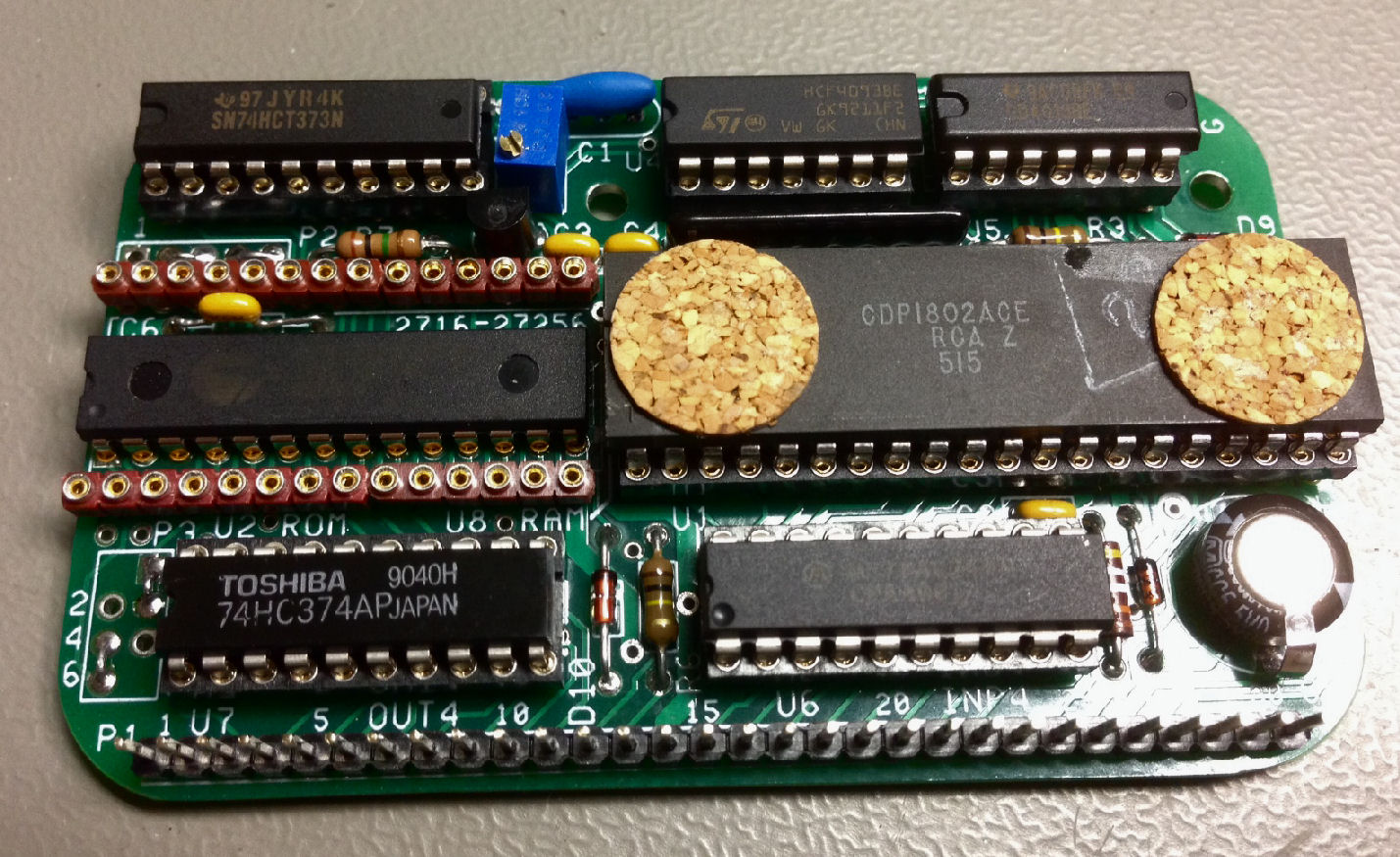
This Tech Note discusses a design change for the Rev G 1802 Membership Card CPU board. The FET 2N7000 used to select addressing in Rev G, was changed to a "resistor biased" NPN transistor. In addition, the resistor SIP R5 was reduced to 10K from 100K (or a collector resistor to +5V of 10K instead). Why? The A15 signal produced by the FET, was not reliable. Later revisions included this change or other changes. If you just want the "fix" read immediatel below. If you want the details, read the rest of this Tech Note. The Rev G manual is on the Rev G support Web page. and includes installation of the NPN and SIP (but not the single-resistor alternative fix).
For more information, contact Lee Hart on his Membership Card ordering Web page. For the current 1802 Membership Card version and how to order, Check the Membership Card "home page" - Herb Johnson
The FET 2N7000 used to select addressing A15 in Rev G, was changed to a FJN3301R NPN "resistor biased" transistor. In addition, the resistor SIP R5 was reduced to 10K from 100K (or a collector resistor to +5V of 5K can be added). Both changes - resistor and transistor - are better; changing the resistor by either method may be sufficient.
replace R5 SIP: Change the R5 SIP from 100K to a 10K SIP resistor pack; it will slighly increase current consumption. Or (not and) add a single resistor as described below. The R5 SIP is the skinny black component with nine pins, between the 1802 CPU and the 4093 IC. Check the Rev G manual for more information, the manual is on the Rev G support Web page.
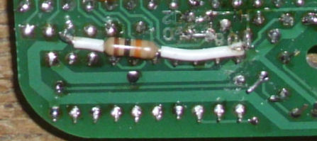
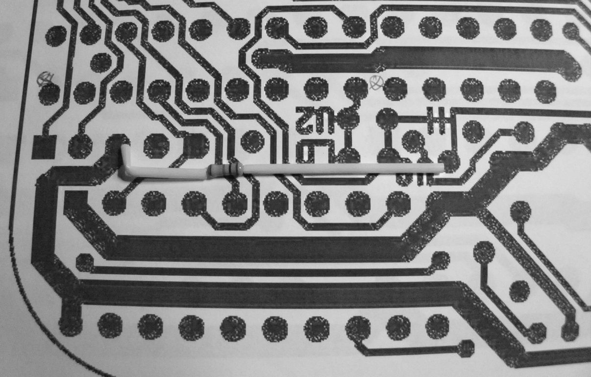
add a pullup resistor: decrease the FET 2N7000 pullup resistor to 10K from the 100K value in the R5 SIP resistor pack. A "field" fix is to solder-in an add-on 10K resistor, from the FET drain pin, to Vcc on P2 pin 3, on the back of the CPU board. Here's a imaged mockup of where to place that resistor. Insulate the resistor wire as shown, with insulation stripped from a wire. Lee Hart suggests an alternative placement on the IC side from the HI hole to a Vcc hole near D10 & R6.
July 2017 note: Operation of the Rev G CPU at 4MHz was possible, with a 1K pullup resistor and the FET 2N7000. This speeds up /A15 and avoids a conflict of both narrow and wide RAM/ROM sockets being briefly selected at the same time. Thanks to Bill Rowe and Lee Hart for these determinations. Chuck Yakym also used a 1K resistor at 2Mhz, as described below.
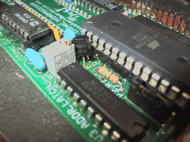
replace FET with FJN3301R: This photo shows the placement of the FJN3301R in Q1 location. (the R5 SIP is yellow and already changed from 100K.) Notice the transistor body is rotated about 45 degrees to properly align with the Q1 thru holes. Digi-Key Part Number FJN3301RTACT-ND, cost 10 for $1.85. Or, contact Lee Hart.
Here's a description from the Rev G manual, about placing the FNJ3301R in the Q1 location on the CPU board.
reported Mar 13 2015, updated April 5 2015: Some Rev G owners report problems with their CPU boards; they fail to access some ROM or other memory devices at 8000H. The problem is the FET 2N7000 circuit, a too-slow risetime for the "HI" signal (addresses 8000H and above). "HI" is pulled down by the FET Q1, and routed to one of the RAM or ROM pin 20 chip-enable pins. This may be visible on an oscilloscope, but the oscilloscope probe may add capacitance and makes it look worse, or crash a running program. This problem may depend on choice of ROM or RAM as enabled by the FET. The solution is to decrease the pullup resistor and also to replace the FET 2N7000 with a FJN3301R transistor circuit with less capacitance. Some RAM and ROM models might also be avoided. Below are details of design and in-field fixes, and descriptions of the problem. - Herb Johnson
design change, April 5 2015:- 1) change SIP R5 from 100k to 10k; 2) change Q1 from 2N7000 FET to FJN3301 NPN resistor-biased-transistor - Lee Hart Lee Hart adds: "I will send out the replacement 10k SIP *free* to any rev.G customers requesting it." Contact Lee by email, as you did when you ordered.
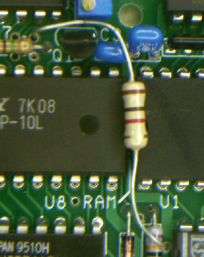
fixes - pullup resistor: One field fix is to decrease the FET pullup resistor to 10K (or lower, see Chuck's work below) from the 100K value in the R5 SIP resistor pack, by adding a parallel single resistor to the board. See the "fix" section for specific ways to do that.
Chuck Yakym independently reported this problem. He found he needed a 1K resistor to support a CY7C199 RAM; 1K also worked for his AM27C256 PROM, but it's possible 10K might have also worked. Smaller resistors decrease the "rise time" but eat a little more power. (The M/S card draws about 12-16mA or less in operation. OHm's Law tells you a 1K resistor with 5V across it draws 5mA.) - Herb
testing:The simplest program to evaluate memory access is: Read memory at address in R4 (LDA 4); increment R4 (INC 4); loop back to read (BR 0000, or BR 8000, whereever this program is toggled in). That will "march" through all memory; the address problem manifests itself when this program "crashes", probably due to corrupting the data lines as the CPU reads and runs the loop. YOu may have to pull the data pins of the ROM or RAM out of the socket to avoid a "crash" during testing. Add "code" to display a result (like toggle Q), or use an oscilloscope to monitor address line activity, etc. How to toggle in programs, is part of the kit's test program docs.
marginal RAM, ROM? Mar 24, Lee Hart: I have three different versions of these 32k 0.3" RAMs: Cypress CY7C199-35PC, Hitachi HM62256BLSP-12, CXK58257ASP-10L Only the Cypress CY7C199 crashes! With the stock 100k pullup [and FET], both Cypress parts fail. With a 10k pullup, one works, and one failed. Mark Thomas used a Hitachi ROM 27256G-25; he saw a very slow-rise signal but his ROM operated without a 10K pullup; he estimates 3us rise-time.
fixes - new R5 SIP:For immediate distributions of the Rev G kit, Lee Hart will change the R5 SIP to a 10K SIP resistor pack; it will slighly increase current consumption. Previous versions of the M/S card CPU have a different /A15 circuit and don't have this issue or need any changes. Later versions will have another /A15 circuit. Rev G owners can contact Lee by email, as you did when you ordered.
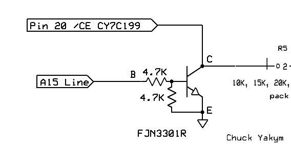
fixes - FJN3301R transistor and SIP change, Chuck Yakym, Mar 27 2015: "Here are my test results using a FJN3301R NPN transistor (with 4.7K/4.7K biased resistors). Membership Card CPU board state: Q1 removed and replaced by the FJN3301R (after reconfiguring the basing of the leads correctly). R5 SIP removed and replaced with the different value 9 pin resistor SIP packs. NOTE: No other pull-up resistor was used on the /CE line.See attached schematic. [Memory under test is CY7C199.]
Vcc=5vdc, Clock Speed = 1.80MHZ

Resistor
Pack		/CE
Value		Rise time	Waveform
10K		1us		5v Peak to Peak
15K		1.5us		5v Peak to Peak
20K		2us		5v Peak to Peak
22K		crashes when probed
33K		crashes when probed
The 22K and 33K value resistor packs kept the 1802 running correctly, however I was unable to measure the waveform. The [10:1] scope probe appears to load the circuit down and when attached the 1802 stops function correctly. Without the probe attached then all appears good. This problem did not occur using the 10K, 15K, or 20K value resistor packs. [Note: Lee Hart suggests the probe adds capacitance. - Herb]
This photo shows the placement of the FJN3301R in Q1 location. Notice the body is rotated about 45 degrees to properly [align with] the Q1 thru holes. The [yellow] 20K (R5) resistor SIP pack is installed. I plan on using the 20K version of this and permanently install this configuration into my current Rev. G. Membership Card. - Chuck. [Digi-Key Part Number FJN3301RTACT-ND, cost 10 for $1.85 - herb]
Here's a description from the Rev G manual, about placing the FNJ3301R in the Q1 location on the CPU board. The Rev G manual is on the Rev G support Web page.
Fix for Bill Rowe, June 2017: Bill reported problems with /A15 at 4Mhz clock operation with both RAM and ROM sockets in use. His Rev G still had the 100K pullup SIP, and the FET 2N7000 for /A15. The simple solution was to add a 1K pullup resistor to the FET. This increased its current consumption, but the ROM in use consumed even more current.
Lee Hart revisited this problem in July 2 2017, in a cosmacelf discussion about choice of FET or transistor switch for /A15. Cecil Bayona suggested a BS170 or BS270 as a faster version of the FET 2N7000. - Herb.
I tried them. They are indeed faster and easier to get; but they are not much faster. They are still "power" MOSFETs, intended to switch high-current loads.
The problem is the MOSFET's capacitance. Look at the BS270 data sheet:
C(iss) input capacitance = 20pf typ
C(oss) output capacitance = 11pf typ
C(rss) in-out capacitance = 4pf typ
A normal CMOS part's input capacitance is something like 5pf. This part has 4 times more input capacitance. This slows down the rise/fall time of the input signal. The output capacitance is also large. Since the circuit has a pullup resistor, that output capacitance slows down the [R-C] rise time.
But C(rss) the reverse transfer capacitance is the real killer. The "Miller" effect means that this capacitance gets multiplied by the gain of the device. Since the gain of the MOSFET is large, this capacitance dominates the other two. All this results in a surprisingly slow rise time when the MOSFET tries to turn off.
I selected the 5LP01SP [and 5LN01SP for Rev H2] because it is a *signal* MOSFET; more like the ones inside a CMOS gate. Its specs are:
C(iss) = 6.6pf typ
C(oss) = 4.7pf typ
C(rss) = 1.7pf typ
Its lower capacitance means it is about 4 times faster in-circuit. I also like the small package (SC72), and that it has a built-in zener protection diode on the gate. - Lee Hart
Note: The 2N7000 FET has a similar Miller effect problem. Also the original large 100K pullup slowed its turn-off time. A smaller pullup sped it up. In rev H2, Lee uses a pull-up/pull-down pair of FETs, with no pullup - much faster, and minimal current consumed. - Herb
This page and edited content is copyright Herb Johnson (c) 2017. Contact Herb at www.retrotechnology.com, an email address is available on that page..