![[Ithaca DPS-1 2016]](ith_feb16_open.jpg)
This Web page created Feb 16 2016, on work to Mar 17 2016, last edit May 7 2018. There's a notes file that has additional work to March 26. Busy back in 2016... copyright 2018 Herb Johnson
![[Ithaca DPS-1 2016]](ith_rob_run1.jpg) I started work on this Ithaca Intersystems DPS-1 system in feb 2016; I recieved it a few years prior, from Andy Robinson. On this Web page, you'll see how I cleaned it up and got it operational; and what I learned and how I learned it. Part of that education, was
working on Kipp Yeakel's Ithaca DPS-1 boot disks, although I've used the disks that came with this system.
I started work on this Ithaca Intersystems DPS-1 system in feb 2016; I recieved it a few years prior, from Andy Robinson. On this Web page, you'll see how I cleaned it up and got it operational; and what I learned and how I learned it. Part of that education, was
working on Kipp Yeakel's Ithaca DPS-1 boot disks, although I've used the disks that came with this system.
Another DPS-1 system I worked on previously but now completed, is described on another Web page.
This Web page is one of a number of repair and restoration Web pages I have which are linked from this Web page My S-100 Web pages have a home at this Web link. I have an Ithaca Intersystems documents Web page at this link. - Herb Johnson
Index:
Initial inspection, chassis & bus repairs of Robinson system
Initial inspection
Rust and repairs
Power-up Operation, early Feb 2016
Board repair and disk work, Feb-Mar 2016
Booting up the Robinson chassis with 4c STD
Running and examining 4.c STD
Progress with board test & repair, 2nd DPS-1
On exhibit at VCF-E XI; RAM problems
Specific repairs
Reforming caps, looking for shorts
Jumper settings of DPS-1 boards
Extra set of DPS-1 boards
keylock repair
Boot & system disks from Robinson system
Memory tests
History of ownership, by Andy Robinson
on another Web page: Kipp Yeakel's Ithaca DPS-1 boot disks
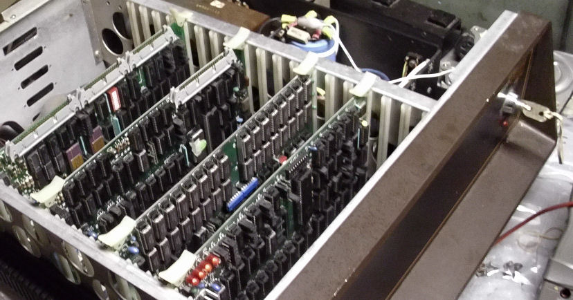
![[Ithaca DPS-1 2016]](ith_feb16_openside.jpg)
Opened the chassis to reveal the four S-100 cards. Note the power key in back.
Side view of chassis. From back to front: I/O card, floppy controller, RAM, CPU.
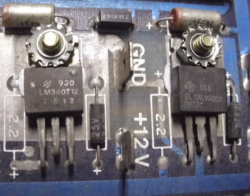
Back of the Morrow Wunderbuss backplane. See how the nuts on the voltage
regulators are rusted? This is common on these backplanes.
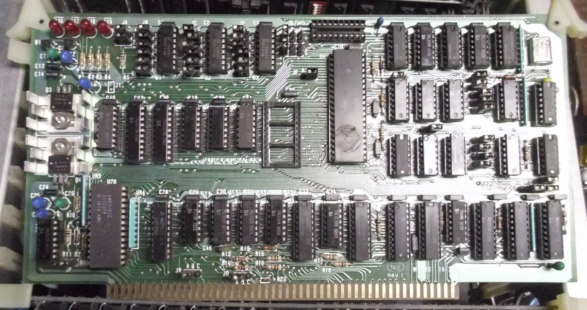
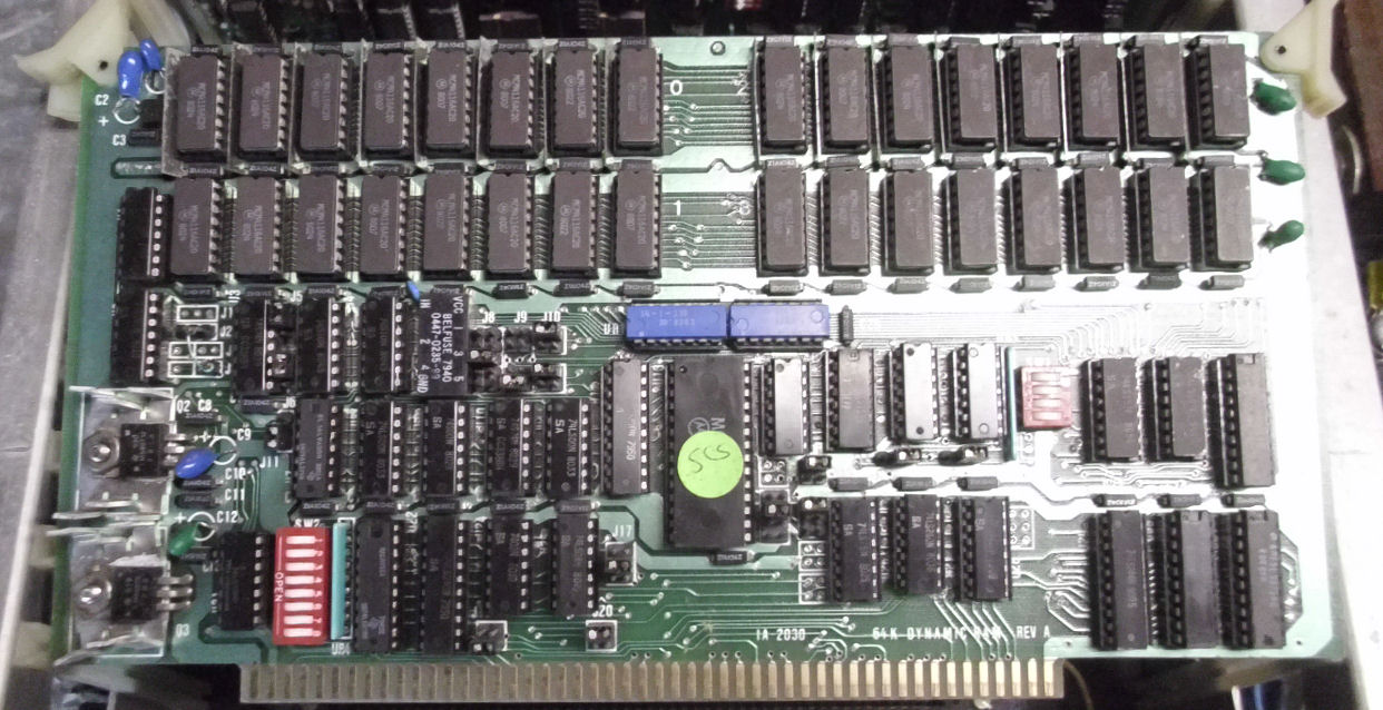
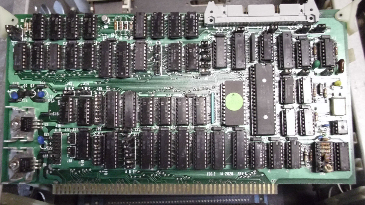
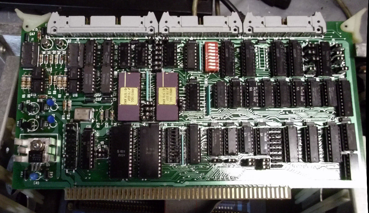
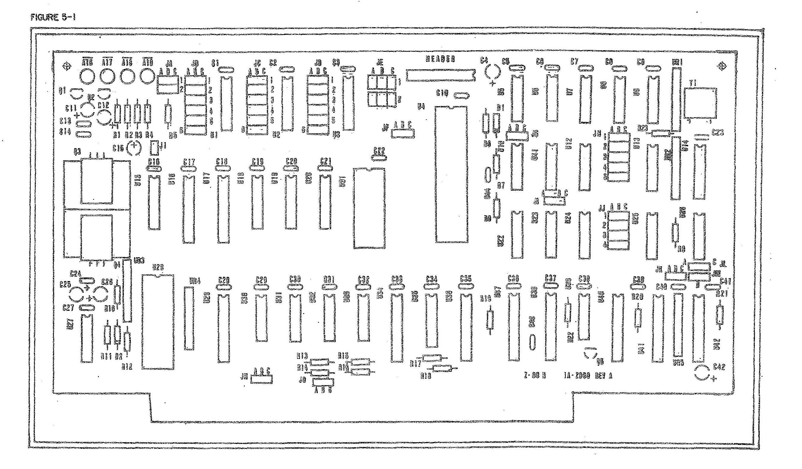
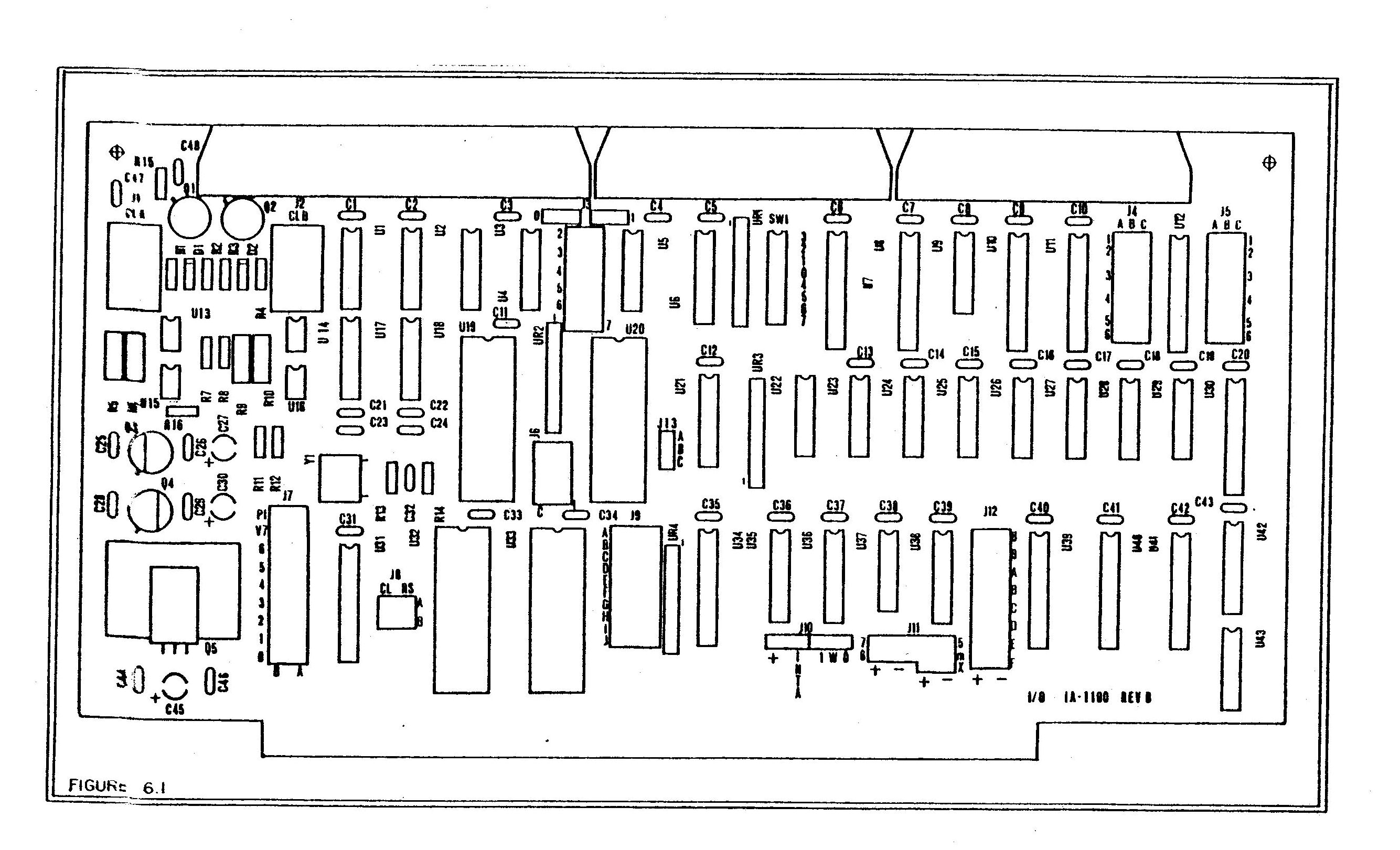
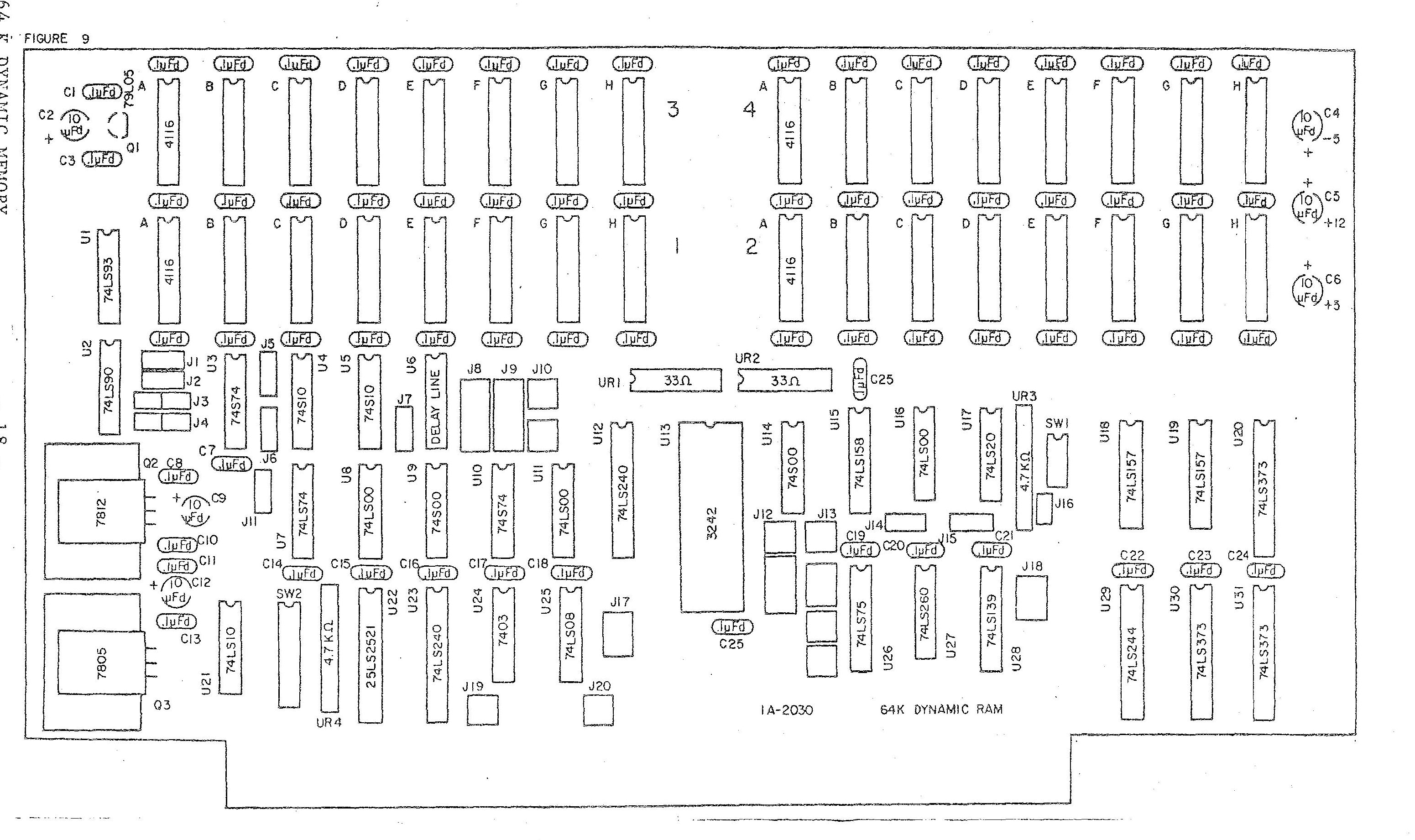
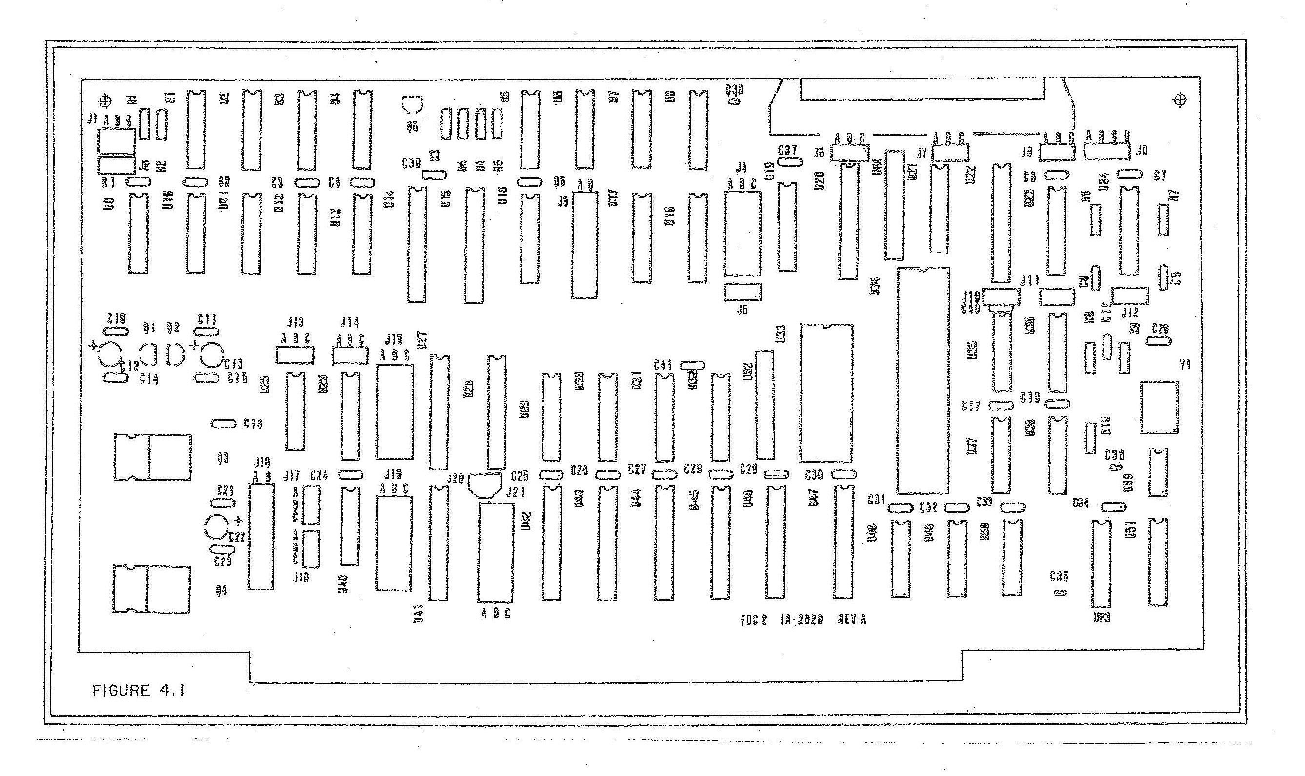
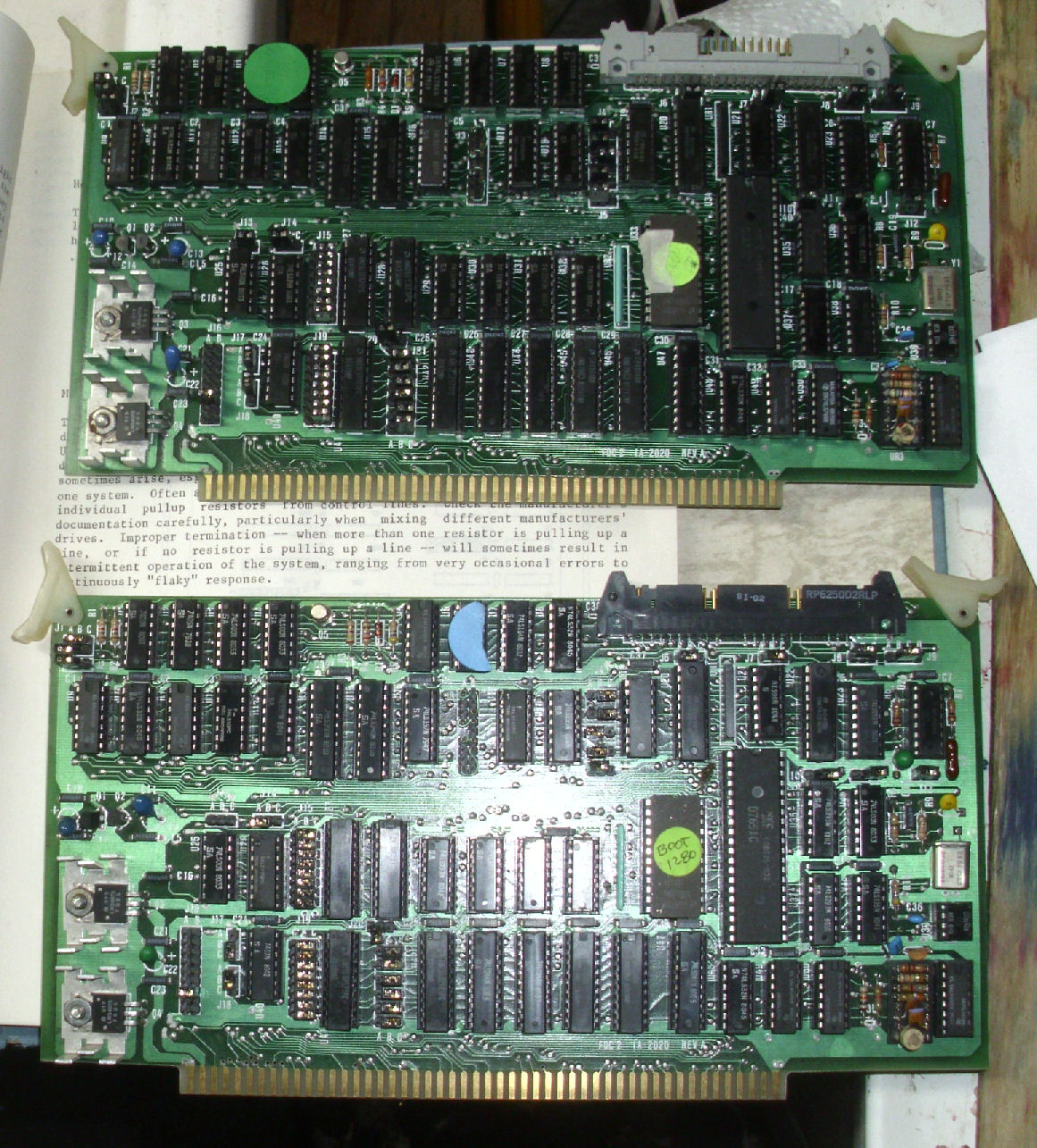
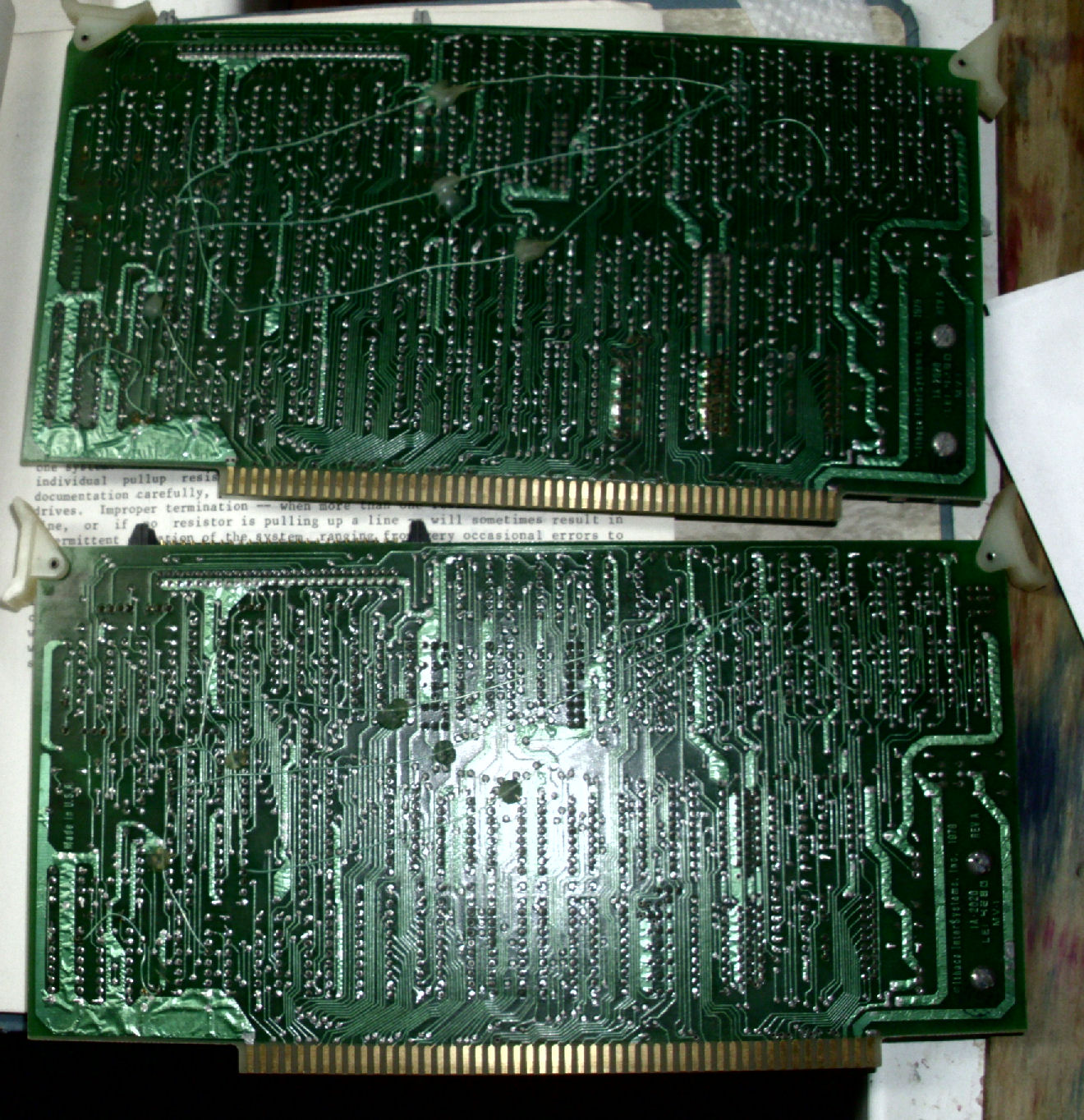
S-100 cards:
Z80 CPU board
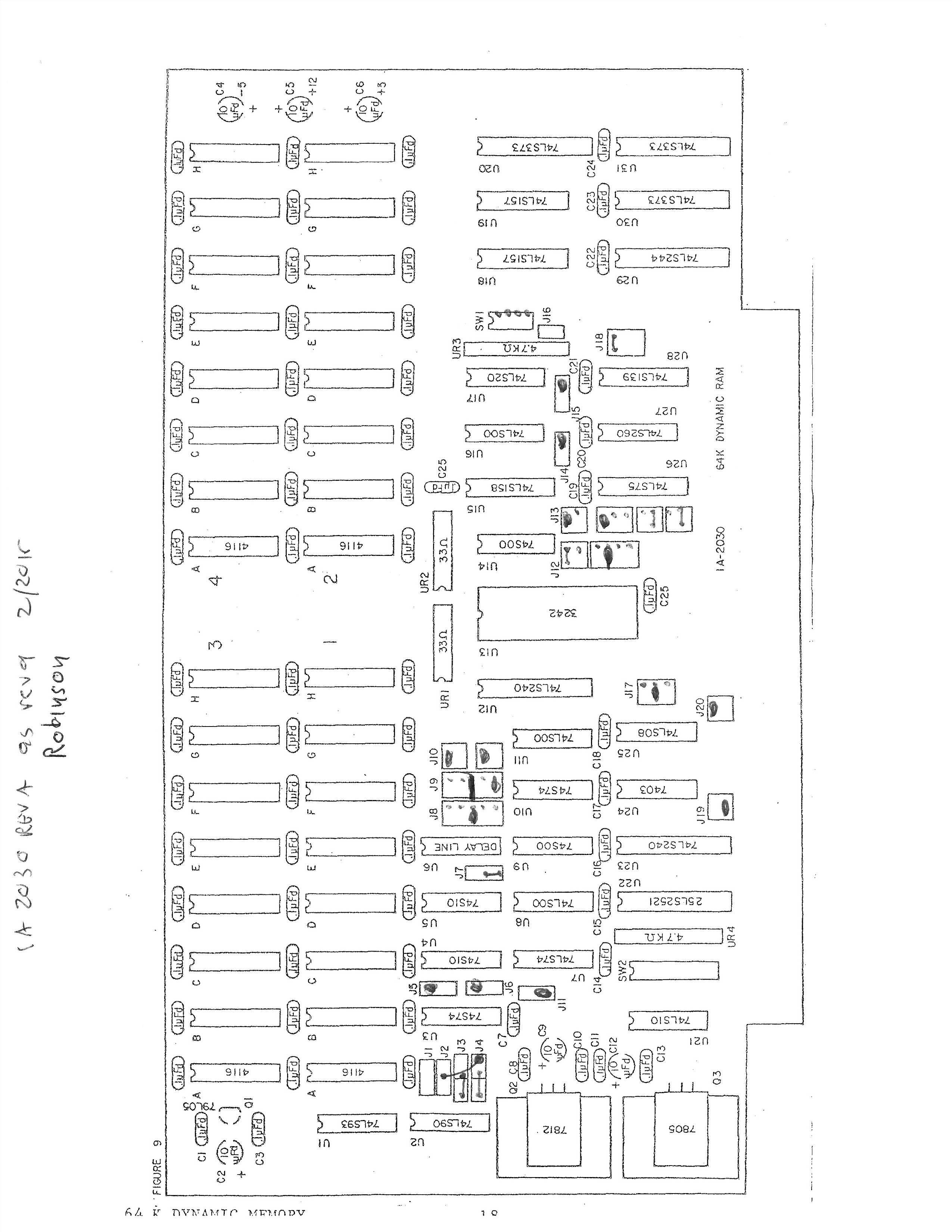
IA-2030 64K DRAM board
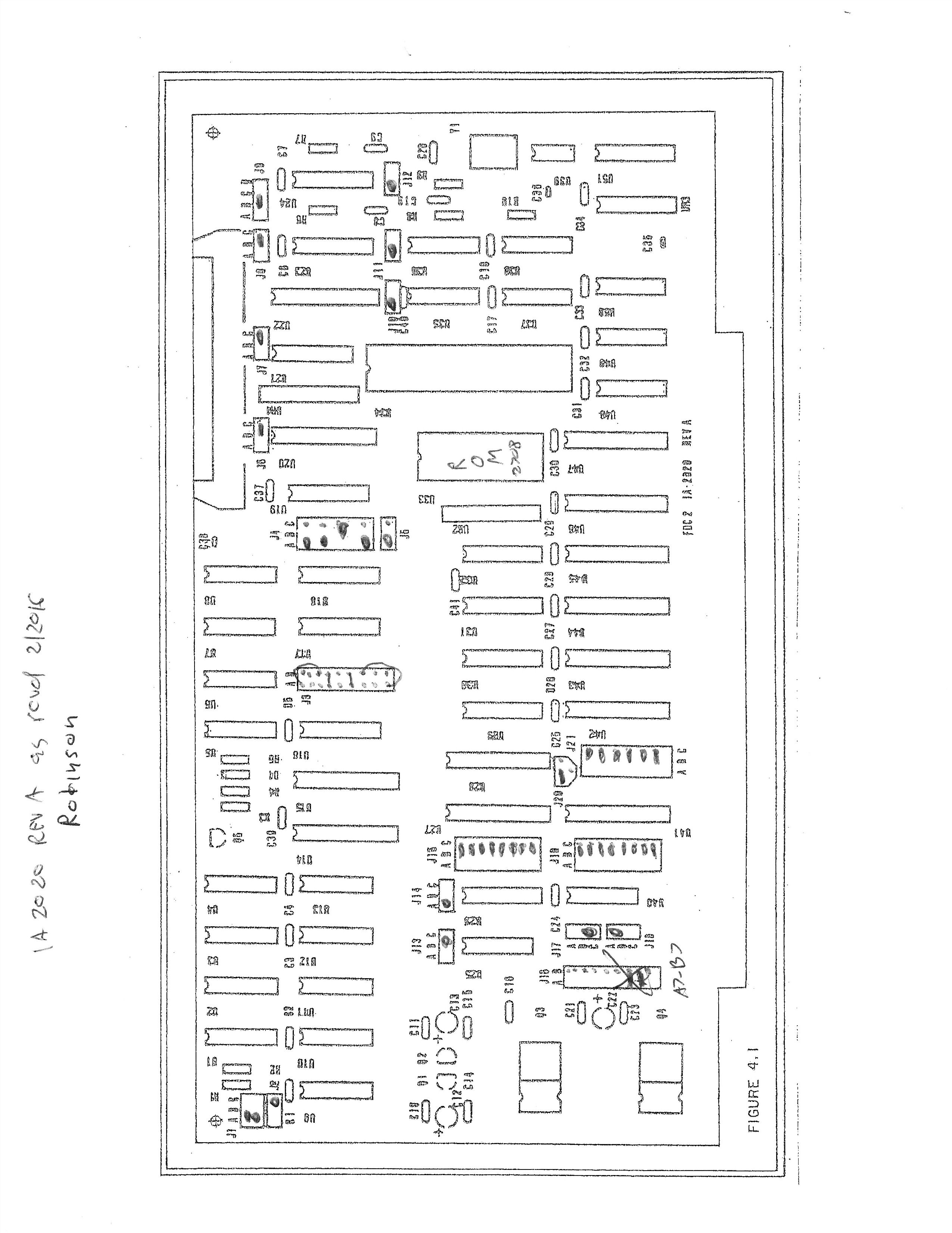
IA-2020 Floppy disk controller board
serial and parallel I/O board
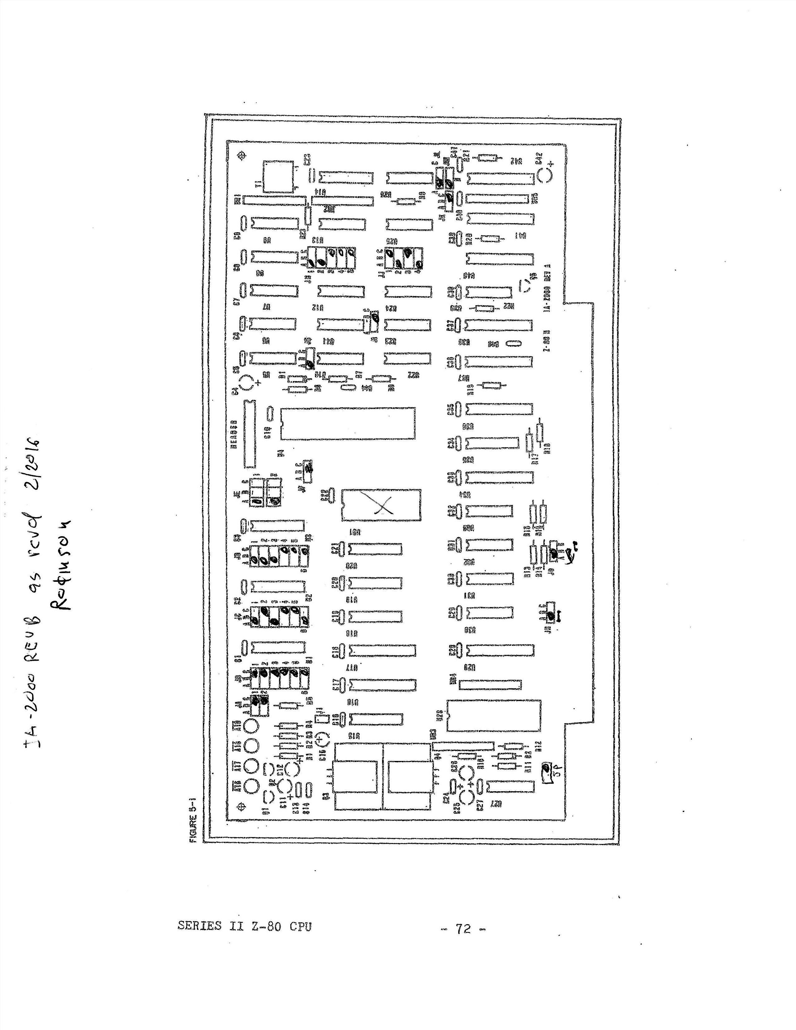
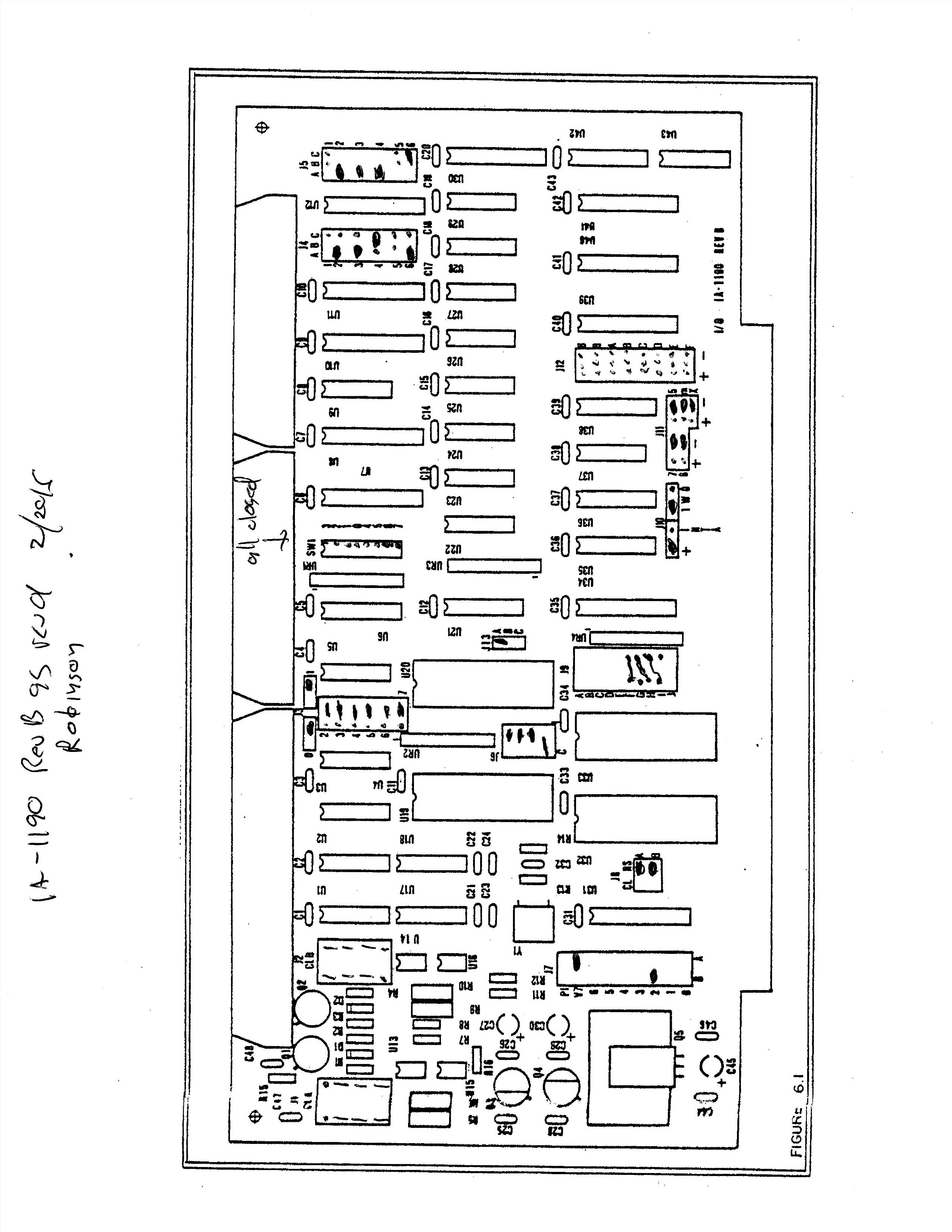
The DPS-1 boards have many jumper settings. Here's a list of the jumpers on the DPS-1 system from Robinson.
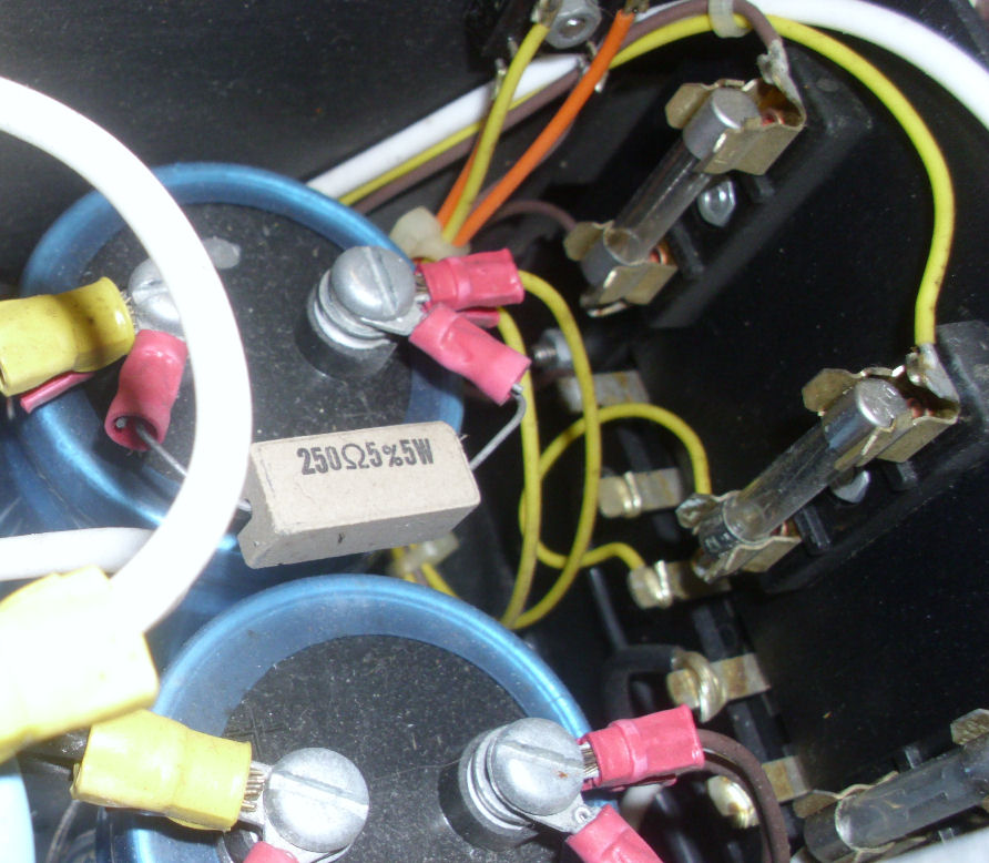
Fuses and bleeder resistors on the DC power lines. The resistors draw down the large caps when power is off, and load the unregulated power supplies to limit peak voltage. The fuses protect the motherboard and S-100 cards when (not if) DC shorts occur.
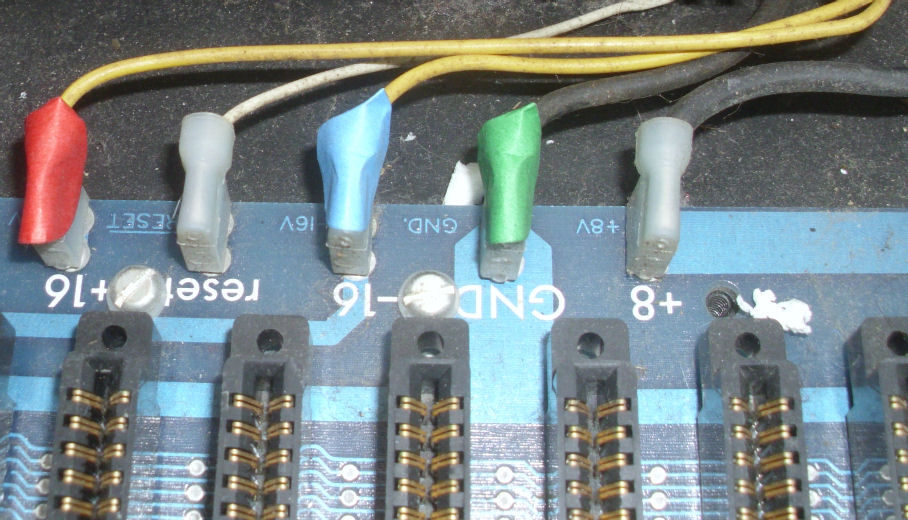
DC power lugs on the motherboard and I added color-coded tags. I'll remove the motherboard for repairs, the colors will remind me where to reconnect.
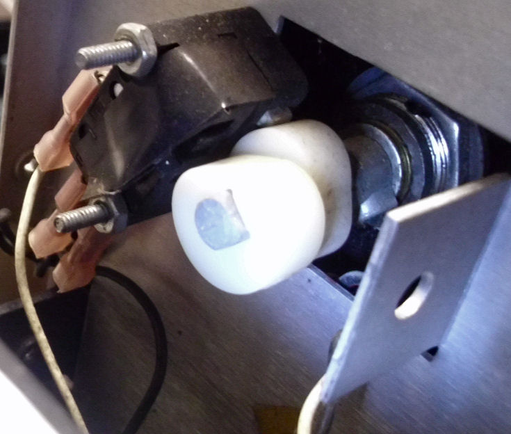
AC power and reset. A keyed switch turns on AC power and rotates further for reset.
However, the microswitch for reset is broken (there's no button following the outer cam). So I'll reset by shorting the
/RESET line to ground.
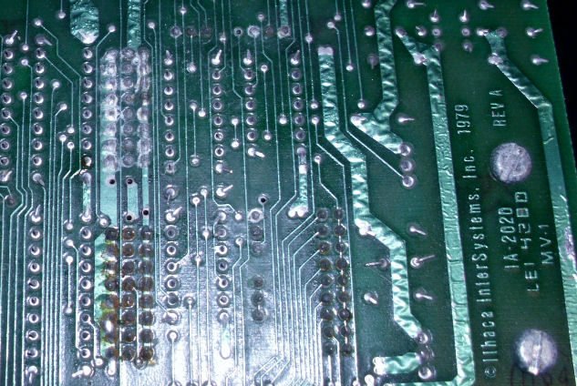
![[Ithaca DPS-1 2016]](ith_feb16_rustnuts.jpg)
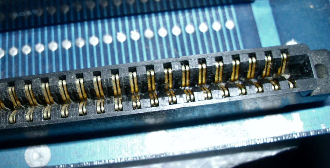
S-100 connector corrosion. The end connector at the front (normally used for the front panel) has some copper oxide on some pins. As the front case has vents, it's more exposed than the other connectors. I cleaned these pins with careful abrasion and DeOxite (a cleaner and lubricant). Here's the cleaned connector later.
I replaced the rusty nuts on the motherboard regulators. Also added thermal paste, which was not there previously.
Inspection of the S-100 connectors revealed the front S-100 connectorhas a recessed pin. This may produce less contact or no contact on that pin. In the photo, the pin opposite the marked paper is darker, because it is recessed into shadow. Why was this pin recessed? This photo shows the pin is low in the connector because the solder end is lower. I decided to mechanically bend the pin in the socket to improve contact. This connector isn't used at the moment. (I should have checked contact with a S-100 card before I put it back in the chassis.)
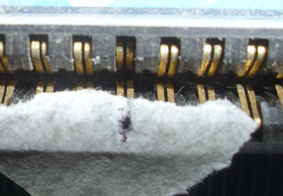
Some components and sockets showed signs of copper oxide, or iron oxide. The back of this board shows some solder pins with some kind of mold, apparently growing on leftover solder flux. Some other pins seem to have red rust. I used a stiff plastic brush to clear out most of this stuff. One can use various cleaners but some of them just spread the solder flux around and make a mess.
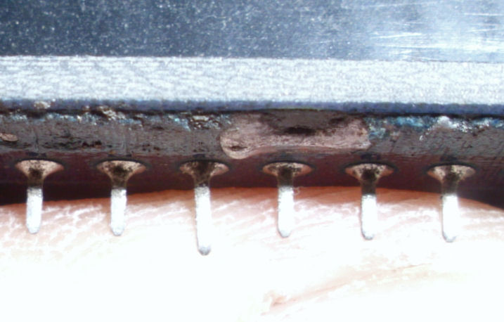
This photo barely shows some white oxide on some
pins in a socketed header. I cleaned this carefully with a small brass brush. Brass will scratch solder, and gold, but not steel. Then I applied DeOxit, a cleaner and lubricant. The lubricant coating provides some protection from air and therefore moisture, the primary cause of such rust.
As I continued to work with this Robinson DSP-1 system, I found more IC's with either black corrosion or tarnish on the pins, or white-oxide corrosion on the pins. Look later in this Web page for details.
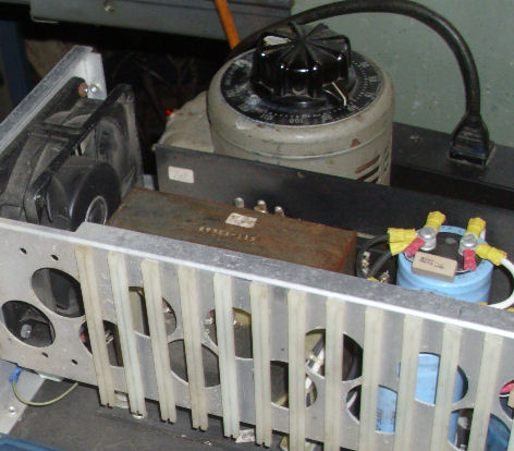
![[Ithaca DPS-1 2016]](ith_feb16_jade.jpg)
With the motherboard back in the chassis, and with this variac I gradually applied AC power to the motherboard. At low voltage I verifyed the terminator had the right unregulated voltages. Now I could reform the large DC caps in the power supply, and check the components of the terminator. Over some minutes I raised the AC voltage and monitored DC voltages, looking for heat or smoke. See
my notes below for details. On the four S-100 cards, I did resistance tests on the DC lines to look for shorts. I didn't find anything, although
some of the DC resistances from +5 to ground were low. again, look at my notes for details.
I reassembled the boards into the chassis, and again started the system at low
AC voltage with the Variac. I monitored the DC regulators on each card, looking for abnormally low DC voltage, as I increased
AC power voltage. As noted above, I was looking for shorted tantalums or other sources of problems. I was pleased to find
no problems of that sort.
The DPS-1 has a ROM in the floppy controller card, which has a bootstrap program. The program looks for the range of available
RAM from 8192 decimal (2000H) up, puts the stack at the top of available RAM, and runs the FDC to load the boot tracks. Unfortunately, without a floppy controller and front panel, there's no activity and no serial transmission: the code waits for the floppy drive to respond.
So I added this Jade brand "The Bus Probe" and observed its operation. sure enough, on
reset the address lights "walked" up the address space, and then stopped blinking. That is, the program loop ran too fast
to see on the lights. I may add a video to show the run-up.
I spent some time in trying to document both my "Robinson" boards, and also to document the boards of Kipp, from whom I got a set of boot disks from his working DPS-1 system. Here's my notes about getting and interpreting those two sets of Jumper settings of DPS-1 boards.
The key things I learned in that process, was that 1) DPS-1 systems were likely very different and 2) I could not expect to run Kipp's disks without
changing many jumper settings to match his system. Also, by referring to DPS-1 docs and these two sets of boards, I had more opportunity to learn
the general details of how these DPS-1 boards COULD operate. Just enough, at least, to become familiar with sets of jumpers versus functions, per card.
The Robinson system came with four diskettes, of which two included boot tracks for bootable operation. here's notes about those boot disks.
As I worked with the Robinson boards, they became less and less consistent in operation. On inspection at the chip level, I found many
rusty chips. I detail problems with rusty chips, on another part of this Web page. There were many TI brand 74ALS74's which were
black with some kind of corrosion or tarnish, which I've seen before. Whatever it is, it leaves the pins dark and fragile, often breaking off if deeply rusted. As my detailed notes describe, I replaced several of those chips.
Eventually, I went through every chip on the four boards to clean or replace, even use
DeOxit on them all. the net result by Mar 6th, was that three of the four Robinson boards - CPU, floppy, I/O - had to be replaced with
identical Ithaca boards with the same jumper settings, in order to get some operation back. Here's notes about how I had
duplicate DPS-1 boards, with some differences noted.
But the good news was, on Mar 6th 2016, with those replacement boards and the Robinson 64K card, was able to boot and operate the double-density Robinson disk to CP/M prompt and disk formatting, on a one-drive setup. But that disk was failing from wear, so I had to
create a bootable disk before I lost it! Another section of this Web page, describes the Robinson disks in hand. The next section describes what I did to create and copy a bootable disk from them.
Here's a ZIP of some files and boot tracks from the "Robinson" single-density 8" disk. Read the notes below, and in the next section, and the notes inside the ZIP files, to understand how I used these, or how you might use these. All these files are subject to change. - Herb
Summary: As discussed previously, I wasn't able to complete the bootup of CP/M from the Robinson single-density 8" disks I obtained with a boot track. It would load the first tracks, seek, and then fail. I also obtained from Robinson a double-density disk, which sometimes would produce an Ithaca "banner" on the terminal, and stop at the A:> prompt. As noted elsewhere here, I removed the Robinson boards and used my own spares and was only then able to boot the double-density disk - but it was very physically damaged from prior attempts.
So I had relatively stable Ithaca cards, and a marginal double-density bootable diskette. Single-density 8" disks I can edit and copy on my Z-100 system. Over the course of a few days early in March, I combined Robinson's single-density CP/M boot tracks (with CP/M and the small BIOS to bring in ISTARTUP), with the ISTARTUP.COM (4cSTD) file from the double-density bootable disk, to create a reliable single-density boot disk. Remember: the Ithaca
CP/M setup is for boot tracks with a CP/M system and a small or "tiny" BIOS, which loads in a STARTUP or ISTARTUP file that overlays that BIOS with the larger Ithaca BIOS.
With that accomplished and bootable single-density disks duplicated, I was able to run the DPS-1 system under CP/M and ISTARTUP/BIOS 4cSTD. But it still wasn't reliable, until I replaced the fourth board, the 64K memory still from Robinson's set, with a spare from my stock. Details of my Memory tests are elsewhere on this Web page.
So what was the difference between the single and double-density Robinson disks? Diagnostic work on the ISTARTUP.COM files from the single-density vs double-density disks, determined that the working ISTARTUP.COM from the double-density disk was version 4cSTD; the not-bootable single-density disk had an ISTARTUP.COM version 4hFST.
This is identified in a short text string, in the first bytes of the ISTARTUP.COM disk file. I discuss those sort
of details where I discuss Kipp Yeakel's Ithaca DPS-1 boot disks. I have not used Kipp's
CP/M or startup - because his disk's STARTUP is 3.c STD, his hardware is jumpered differently, it might not work for good reasons.
But from examining Kipp's disk and comparing them to the Robinson single-density files, I learned what I needed for hardware and software repairs.
Creating usable bootable disks and copying them, would not have been possible except for my Zenith Z-100 system with it's own 8-inch drives to format and copy SSSD 8-inch disks. I had to use Z-100 CP/M-80 programs and utilities include DU and SYSGEN, to copy the system tracks (and
copy seperately the boot sector!), and then to format and copy files. Some related information is on another Web page about Kipp Yeakel's Ithaca DPS-1 boot disks.
With reliable and copied CP/M-Ithaca boot disks, I was able to start running CP/M and programs and do further testing. Early on I described
replacing the Robinson 64K card with one of my spares, when it appeared that memory may be flaky.
March 10: Here's a photo of the running and assembled DPS-1, with the Zenith brand 8-inch floppy drive cabinet and YE-180 8" floppy drives. The terminal computer is an old old Dell 486 system running MS-DOS and QMODEM, a popular terminal and file-transfer program of the era. The Ithaca is running CP/M under the 4.c STD BIOS from the Robinson DD disk; with boot
tracks from the Robinson SD disk. That's what it took. - Herb March 17 update: The following ZIP is files from work I did in 2013, to copy files and boot track from
a copy of a copy of an Ithaca DPS-1 4.c STD distribution disk
which had a boot track and a full set of CP/M and Ithaca files. It may have been a copy of an Ithaca distribution disk. Looking back
at it today, I was able to make more sense of it. And compare it to the actual 4.c STD ISTARTUP file I'm using today. Look at the ZIP
file contents for details. (On March 30th, I booted a copy of this disk, so this disk's version of 4.cSTD and tiny BIOS work OK on my reconstructed DPS-1 system.)
April 5 update: I compared after assembly, the SBIOS.SRC from the Ithaca 4.c distribution
disk (see above) to the BIOS embedded in the ISTARTUP from the Robinson DD disk (which I'm running).
The assembled source matches the running ISTARTUP BIOS. Likewise: I compared after assembly, the
PICO.SRC from the Robinson SD disk, to the embedded BIOS in the boot tracks of that same disk
(extracted by me as IBOOT_SD.COM). These two binaries match. Therefore, I've added those sources and my comparision notes, to the ZIP files accordingly. The assembler used was ASMBL, from yet another
diskette, which has Ithaca's PASCAL/Z compiler and that assembler and associated linker.
I will produce in due course, a single ZIP archive, of the files and tools I've accumulated,
to test and run my DPS-1 system under Ithaca's 4.C STD BIOS. That "archive" set of working files continues to be refined. Here's what may be a non-current version of my archive
of working Ithaca 4.c STD BIOS files and CP/M tools.
Board repair and disk work, Feb-Mar 2016
Booting up the Robinson chassis with 4.c STD
Here's a ZIP of some files and boot tracks from the "Robinson" double-density 8" disk.
Here's a ZIP of all the files and boot tracks from a copy of an Ithaca SD 8" disk for ver 4.c BIOS/ISTARTUP.
Here's what may be a non-current version of my archive
of working Ithaca 4.c STD BIOS files and CP/M and tools.
Running and examining 4.c STD
Progress with board test & repair, 2nd DPS-1
![[Ithaca DPS-1 2016]](ith_2012_boxed.jpg)
As of March 10th, I had a working DPS-1, from the Robinson chassis with bus board and power supply, and a set of "spare" or unaffiliated Ithaca cards. So the next step, is to get another chassis and set of cards running. I had of course, the Robinson cards (green dots) and other spare Ithaca cards (blue and other dots). I also had the DPS-1 system with front panel which I worked on in 2012, but failed to get working. I marked its four boards with red dots. The paper dots of course identify these cards visually. I also added a set of white paper dots to my running boards, identified them as my "#1" set.
So I pulled out that "2012" system, and I started cleaning and testing those 2012 boards, the Robinson boards, and my spares - which could be compatible with the board set I put together. (For instance, the 2012-system's serial board didn't have interrupt controller chips which were in use by the system I repaired here in 2016.) By late March 2016, I got that front-panel system working with a second set of boards. These were identified with white paper-dots as my "#2" set. Follow the Web link for what I did in 2016; additional Web links on the page show what I did in 2012 and earlier.
For results of testing for those #2 boards in March 2016, here's running notes on my progress, board by board, as I tested..
On Mar 27-28, I repaired an Ithaca DPS-1 dual 8-inch drive cabinet with two Shugart 801 drives (single sided). Again I'm short on time to edit a Web page, but here's my running drive-repair notes.
Herb Johnson, Apr 3 2016
I exhibited both DPS-1 systems and 8-inch drives at "VCF-E XI" or the Vintage Computer Festival - East XI (not VCF-E 11), on April 15-17, at the Infoage Center in Wall, NJ USA. Exhibitors on Sat and Sun, talks on Friday, and a vendor/consignment area. Hundreds attended. I was a vendor part-time and an exhibitor full time. Here's my Web page on my exhibit and on the event.
BOth systems ran OK, except for an odd thing; which I also noted on prior testing. The DPS-1 with the "#2 set" of boards, the system with the front panel display, would occasionally "hang" after running programs like memory test, etc. I could not reboot CP/M, and even a power-cycle did not resolve the problem. I determined the problem was centered around the 64K DRAM card - and "cured" it by swapping the #2 64K card and the #3 64K card. When the problem occured again - swapping back the unpowered #2 card again restored operation. My guess is that the 64K board gets into some "state" and can't be reset or cleared under power. Apparently it requires extended power-down to reset itself. Or... it has some intermittant connection that the acts of pulling and inserting the card clears out.
With the motherboard back in the chassis, and with this variac I gradually applied AC power to the motherboard. At low voltage I verifyed the terminator had the right unregulated voltages. NOw i could reform the large DC caps in the power supply, and check the components of the terminator. I gradually raised voltage to about 30%, and let the caps "run" for tens of minutes at that level. I monitored the caps and regulators to check for shorts or odd voltages - none occurred. of course the voltage regulators did not produce much output voltage - they vary in how they respone to undervoltage but most seem to need 1/2 or so rated voltage to produce some output above a volt or two. If they persisted at zero volts out, I would suspect a short on the regulated side.
After running at 30%, I raised voltage to 50% or more, to the point where the regulators just began to produce low but reasonable voltages; and let it idle in that range. Then I raised it to 70-80%, where the regulators produced near-rated voltage; and let it idle there and test. Finally, I ran the chassis at the point where the unregulated voltage was at ratings of 8V and 18V. That was at about 100VAC: I let it run for half an hour at that setting. It's common for unloaded, unregulated S-100 supplies to produce voltages above 8V and 18V when no cards are in the chassis. I briely ran at full AC voltage, just to let the capacitors "know". Caps will reform at whatever running voltage they are supplied; it's better to run them over ratings for some period.
I have not specified exact times or some voltage-raising algorithm. Big caps from the 1970s and 80's seem to be reasonably robust and not need hours of reforming. If you want a calibrated scheme, you could use a constant current DC supply, remove your caps, and run them with a few mA of current, gradually up to rated voltage over several minutes, then idle at 10% over rated voltage for tens of minutes. Initial currents will be higher as the voltage rises, but big caps should not have much DC leakage current.
For each card including the motherboard, I did DVM ohmic tests - looked for shorts - on each board's incoming and outgoing DC regulator. That's a simple way to look for shorted tantalum caps or other issues. I fussed with one S-100 card, looking for a source of a 200 ohm reading; I gave up pulling caps out just to check them, and assumed the low reading was simply the sum of all the IC's on that power circuit.
As for small tantalum caps
I reassembled the boards into the chassis, and again started the system at low AC voltage with the Variac. I monitored the DC regulators on each card, looking for abnormally low DC voltage, as I increased AC power voltage. As noted above, I was looking for shorted tantalums or other sources of problems. I was pleased to find no problems of that sort.
The DPS-1 boards have many jumper settings. I spent much of the last half of Feb 2016, in obtaining and working on these, and comparing them to jumper settings on Kipp Yeakle's DPS-1 system of the same four boards. See another Web page for details of Kipp's system, but his setup is very close to the "standard" settings in one set of Ithaca's DPS-1 manuals.
I frankly worked backwards on understanding these settings. I think it's useful to show what I mean, as I think many S-100 owners find themselves reading and understanding S-100 manuals - and their limitations - as a kind of last-resort effort. I did this "twice" as I was also working with images of Kipp Yeakle's boards.
1) Of course I recorded on paper in text, the physical jumper settings. Most jumpers had markings to describe them, but there's so many! and they are arranged in different ways. I used my own designations of jumpers in some cases.
2) then I went to the manuals for layouts of the boards and jumpers; and to photos of my Robinson boards (and photos only of the Kipp boards). I eventually made JPEG images of the layouts, cleaned and enlarged, and filled in the printed copies for my Robinson boards. This helped me correct my text listings. That included, changing some designations of jumpers to match the descriptions in the manuals.
3) I saw how different, or similar, my Robinson boards were jumpered from Kipp's boards. So I read the manuals in more detail, as they describe both individual settings per jumper, and "standard" settings. I was able to resolve some differences, for instance my Robinson system has no front panel and Kipp's does. But other differences made for very different operation.
4) Kipp also looked at the jumper settings I sent of his boards. He corrected some misreads, and also referred to the manuals for correct designations of jumpers. With repeated experience in looking at the boards and images, and the lists, I re-read the manuals in fine detail for descriptions of individual settings, and made further corrections.
Here's a list of the jumpers on the DPS-1 system as recieved from Robinson. They are very similar to the recommended DPS-1 system jumpers in the Ithaca Intersystems Standard BIOS Manual version 4.c for 8/17/81; and a 64K type 6 setup from the 64K RAM manual.
Here's documents for the Robinson jumper settings as filled-out board layouts, as taken from the DPS-1 manual set.
The CPU layout
The VIO serial layout
The 64K memory layout
The floppy controller layout
For the Kipp system jumper settings, see that Web page. They are different, as he's running a STARTUP file with a version 3.d BIOS.
For other DPS-1 owners, here's some blank board jumper layouts:
The CPU layout
The VIO serial layout
The 64K memory layout
The floppy controller layout
What I learned from this exercise, with Robinson's boards and images of Kipp's boards, is that the DPS-1 systems were likely set up
in a number of very different ways, at different times. Why does this matter? because boot disks from one DPS-1 system won't likely
boot up on another DPS-1 system.. And of course it matters when replacing or swapping DPS-1 boards.
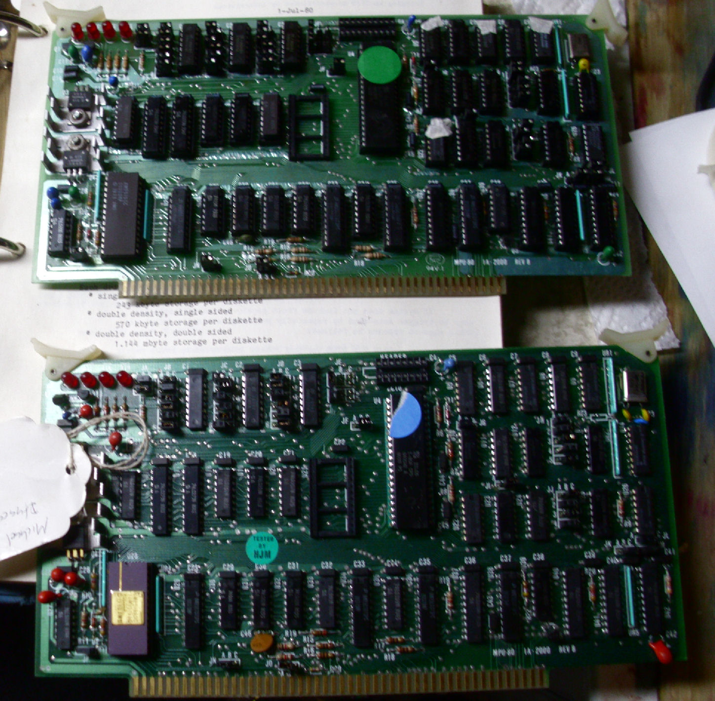
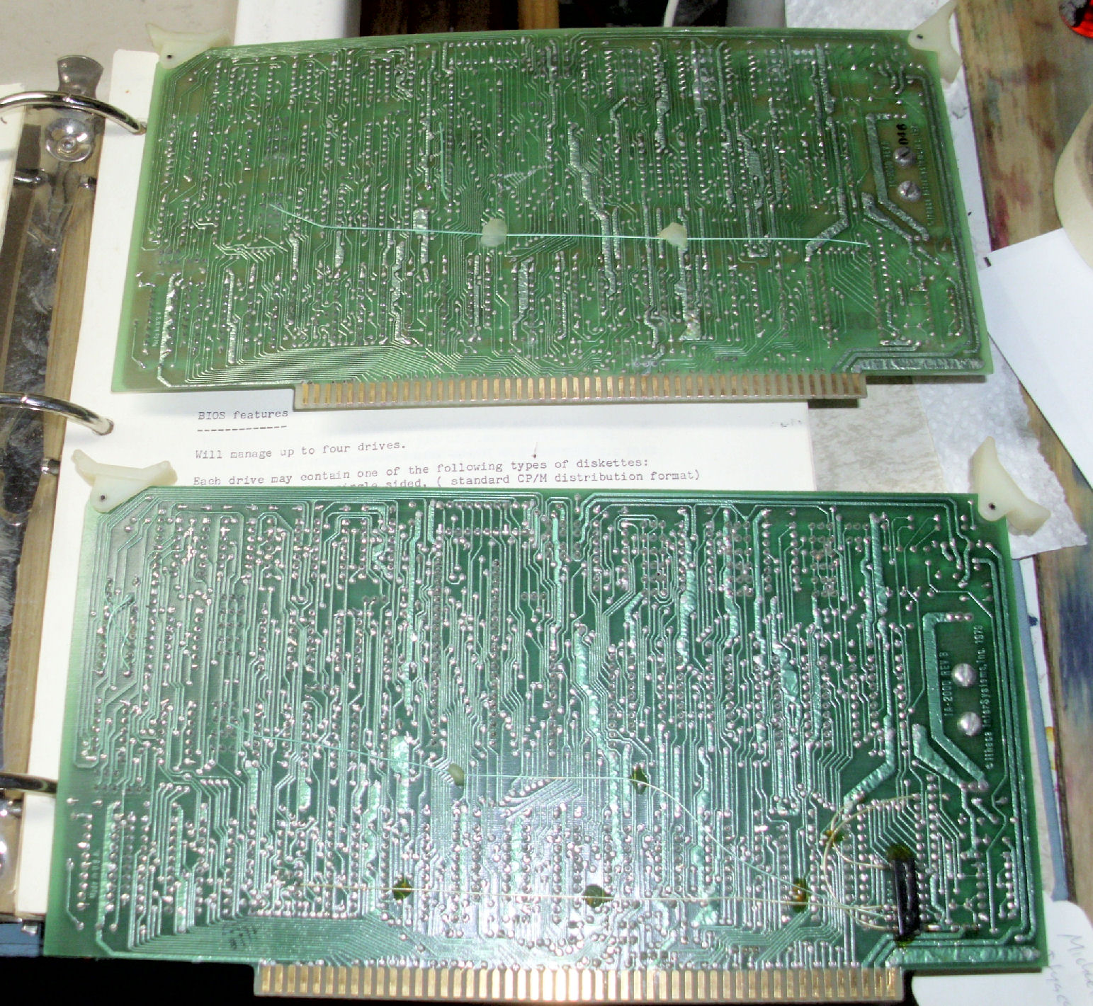
I was fortunate, to have bought several years ago, some Intersystem boards at various times and places. I pulled from my stock, four boards that mostly closely matched the Robinson board set; down to changes from "whitewires". After taking photos as a quick way to preserve their previous jumper settings, I reset their jumpers to match the Robinson boards. I tagged the Robinson boards with green sticky-dots; the substitutes were tagged with blue or yellow paper dots.
For instance, here's a pair of floppy controller boards. The top of the photo shows the Robinson FDC card with yellow sticker; the bottom is the substitute FDC card. Both have 2708 PROMs on them. Both have some white-wiring on the back. The CPU board pair is a little different. Here's the pair of CPU boards from the front, the Robinson board above.
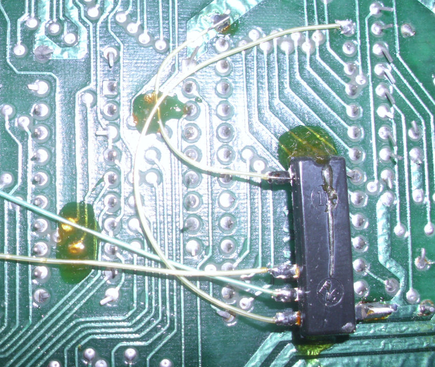
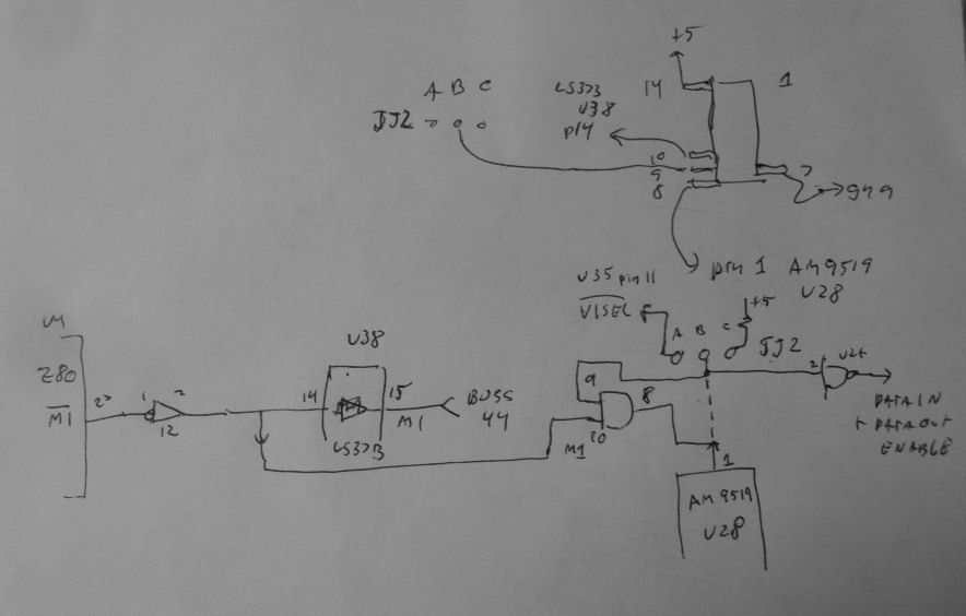
On the back view of both boards (same orientation) the substitute CPU board has a "dead-bug", an upside down chip wired in. Closer inspection suggests the chip is a 14-pin logic chip. I can see pin 7 is ground and pin 14 is +5, so that tells me the pins in use are 8, 9, and 10. My guess an AND or NAND gate, and here's a schematic to suggest how it may be wired in. It seems to intercept M1 from the Z80 processor, to gate a signal to or from the 9519 interrupt controller. The dotted lins is the schematic wiring, which presumably has been cut. JJ2 is the jumper to enable or disable the VI interrupt controller, A-B enables and B-C disables. There's a "revision 0" page in the CPU manual page 74, which discusses this jumper and possible errors if the controller is not to be used but is left on the board. The note says "will be corrected with revision A".
Intel hex format dump of the DPS-1 1K PROM. Source listing is in the "Ithaca Intersystems FDC-2 Bootstrap" manual.
The Robinson system came with four 8-inch diskettes. There are two boot disks, one double density, one single density, which both have code on their boot tracks (track 0 and 1). I verified the boot tracks on a Heath / Zenith Z-100 system with 8-inch drives and diagnostic programs that can read track and sector of any disk. Also under CP/M-80 I used the DU disk utility program from CPMUG archives.
The system seems to run the boot ROM on the floppy controller, that's verified by both the Jade Bus Probe showing expected activity; and by actions on the floppy drive. The 8-inch drive loads and seeks and appears by actions to read in (as far as I can tell) both the boot tracks, and the ISTARTUP file - judging by how the head seeks.
Note: at a later time, I used a Z80 in-circuit device to try to debug the various cards. In go-mode, it could breakpoint and do some work, in stop mode the hardware didn't work well. But I was able to enable the ROM and make an INtel hex format dump of it.
On the double-density bootable diskette (which I can't copy or read on my Z-100 system), it's physically wearing out. With a terminal (emulator on a laptop) set at 9600 baud, I get through the A-side serial port (that's the first 25 pins on the dual serial cable of the VIO), an Intersystem "banner". But the program as loaded responds to only ONE character in, and then hangs somewhere in low memory (01XX). I could not test this a lot, because the diskette has physical wear - rings around the media - and I have only one. I put this disk aside in February and only worked with the single-sided disks (copies or original).
The single-density disks are "standard" 26-sector interleave-6 type CP/M disks. So these can be copied and file-read on my Z-100 system, and I can format more standard SSSD disks. I can also recover the files - look elsewhere on this Web page for an archive of those files. In February, after initial repairs: I attempt to run on the Robinson system, either a copy or original SSSD disk; the floppy drive also appears to read the boot tracks and ISTARTUP - but the console displays nothing. As I made more repairs and replaced IC's in February and into March, I wasn't able to get a response from the Robinson boards.
After replacing most of (later all) the Robinson cards, I able to boot the now-damaged double-density disk with its boot tracks and ISTARTUP.COM file - barely. Now I had to build a clean diskette for use, as described elsewhere on this Web page.
![[Ithaca DPS-1 2016]](ith_feb16_panelfix.jpg)
As noted above, the power/reset switch was damaged. It's an Acme keyswitch which rotates two cams. One cam operates a AC power microswitch; the other cam the S-100 reset line. The reset microswitch was inoperable. And, as I worked with the DPS-1, I found that jiggling the keyswitch would power down, because the cam only marginally held down the microswitch.
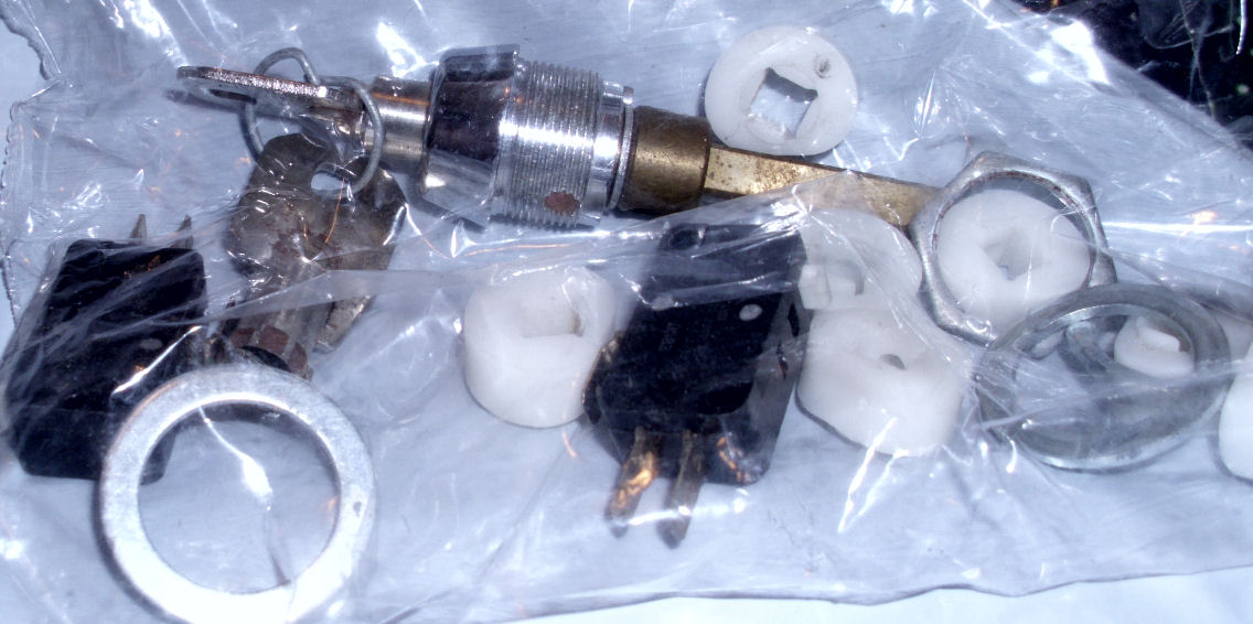
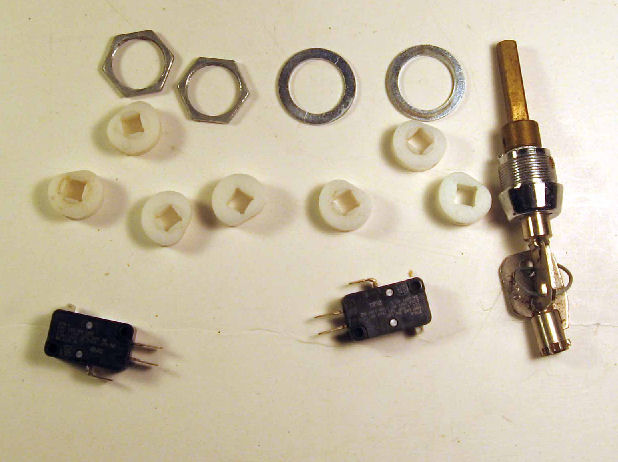
My good friend and colleage John King, supplied me with a set of Ithaca keyswitch parts and microswitches.
For more detail, here's another photo of the AC/reset parts. Replacing the reset microswitch was no problem. Too much time spent futzing around, revealed to me that the key mech on the front panel,
was flexing relative to the microswitches on the chassis. The problem wasn't with flexure on the key mechanism, it was the plastic panel on which
the key mech was mounted. The solution was to stiffen that panel by mounting another screw and adding a wedge at another panel mount point. the added screw is on the upper right corner of the image; the wedge is some orange plastic at hand. This seemed to
greatly reduce the flexure of the panel. It wasn't a complete fix but better than before. Work goes forward....
Through the last two weeks of February and into March, as I tested the Robinson cards, they seemed to be less functional. that is, when attempting to boot the terminal stopped producing a displayed "banner" text from the DPS-1 booted CP/M.
Finally, in early March I literally went through every single IC socket and chip. I pulled each chip, examined and brushed (brass brush) the pins, and put DeOxit on each. This took a few hours of intermittant work. I found a few more corroded chips. I found another TI 74ALS74 which had a broken pin - I had to pick the pin out of the socket! When I did all that - the boards became more intermittant and often failed to even read past the boot tracks after reset.
On March 6th, I replaced in turn, the serial board, the CPU board, and the floppy board - all three - with spares I had previously tested individually. They would not boot-to-prompt the single-density boot disks (Robinson's or my copy). But they did boot the double-density disk
to the CP/M prompt! I was actually able to get "DIR" and even format (in the A drive) a double-density single-sided diskette!
![[Ithaca DPS-1 2016]](ith_rob_memrs.jpg)
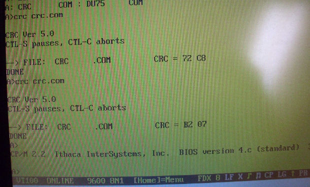
March 8-10: Once I had the DPS-1 booting up CP/M more-or-less reliably, I could do some memory tests to see why the "Robinson" 64K card might be unreliable. I was concerned it was not reliable, because I got "funny results" when trying to run various programs. For instance, a popular CP/M 80 program was "CRC", which created a list of complex checksums for files. It's a good check on diskette reliability, or to see if your file had changed. But running it on itself, should not produce different checksums!. Also, I got odd results on trying to run other programs.
So, I changed the 64K memory card to one of my spares, and dug out my old CP/M memory test programs. One of my favorites was MEMRS. It performs a series of memory-pattern tests and repeats them until failures; and describes the failed address and bits. I ran this program for some time on the "spare" 64K card, and it seemed to run well enough. I also ran a program "WORM", which is a Z80 program that copies itself up through memory, and uses BIOS to report its current memory location. (Z80's execute from memory faster than they read memory - look it up.)
But the card was not particularly warm and the chassis was open. The DPS-1 has a 4-inch fan and good ventiltion anyway. Someday I'll do hot-board tests.
After doing other software work to produce good bootable disks and working copies, and adding these and other programs to these working disks,
I put the "Robinson" 64K card back into the chassis. Before putting it in, I made sure all the chips were well-seated in the sockets. A few made that
"crunch" noise that suggests they were not. I ran the same MEMRS for some time with the "Robinson" 64K board, and it seemed to work OK now. In due course I'll diagnose the other removed Robinson boards.
Here's notes from Andy Robinson, near Toronto in Ontario, Canada, who provided this system to me in June 2015. My edits are in []'s, Andy gave permisssion for use. - Herb
This computer was originally used in the Animal Science Dept at Cornell University [in Ithaca NY where Ithaca Audio was located.] (I guess they wanted to buy local). It was retired in favour of a Xerox 820 and given to a secretary to take home for her moonlighting thesis-typing activities using Wordstar. Her husband was a fellow grad student and none of us had any money in those days.
I think her serial terminal died and she wanted something more integrated. So I took the DPS-1 in trade for building her a Z-80 Big Board [BB] computer kit to replace it. She was using the Xerox 820 at work and it was based on the BB as well, so she liked the platform. I built her BB to use the Lobo dual [8-inch floppy] drives from the DPS-1.
I used the DPS-1 a bit but I had to use Kermit on my own BB as the serial terminal to run it and split off one of my two floppy drives to boot it which made no sense since the BB was an equally good computer that took up less space and power; so I quit using the DPS-1. After languishing for a bit, I discovered it had what I think was a dead capacitor and it wouldn't run anymore. Eventually, she replaced the BB with a PC and gave me the BB and the dual 8" Lobo drives from the DPS-1, which I used on my BB (wow, a 4-drive system, woohoo). Soon after, I had an IBM AT and my BB was boxed up along with the DPS-1, the extra BB, the drives, all the disks, docs etc.
I finished my degree at Cornell and returned to Canada. I have moved the DPS-1, BBs, drives, disks and docs from place to place for at least 30 years. Why - I don't know! Perhaps now is the time to send the DPS-1 where it might have some use / value. I haven't opened the case since checking the power supply over 30 years ago. It probably is dusty / dirty / corroded / ugly inside and outside but whatever cards were in there when it ran are still in there. It was stored in a sometimes damp garage for 15 years so it is likely showing rust on the bare steel inside also.
I still have my BB, the Lobo drive system etc. It booted and ran CP/M when I last tried it about 4 years ago. So those bits and all the disks aren't up for grabs.
[Andy also kept the Ithaca DPS-1 manuals, and several boxes of Ithaca system disks and software. Ithaca had their own assembler tools, Pascal development tools, and other CP/M programs. - Herb]
[I agreed to consider the system, so Andy checked its condition. - Herb]
I unearthed the DPS-1, brushed off the dust, opened the case and took some photos. I didn’t power anything up but I released each of the cards from the cage and checked connectors etc. The interior is showing limited signs of red rust on steel items like the front panel key (which is still there!), transformer plates and some screws but no obvious signs of other types of oxidation on any of the the circuit boards, connectors etc. The fan spins freely so the bearings haven'tt rusted up on that either. I was actually quite pleased at how clean it is given that it has been sitting under a workbench in a couple of different unheated garages for the last 25+ years.
Interestingly enough, the secretary who got the DPS-1 and then the second BB also lives in New Jersey now. We visit them every couple of years or they stop by our place if they're passing through on the way to visit his family who live near us. If we plan a stop-off to visit them in New Jersey, the shipping might end up being really cheap.
[Or] we are probably visiting friends in Mass. this summer so I could bring it south of the border and ship it locally if you're interested. Alternatively, I could remove the cards from the card cage and ship them via USPS if the chassis is of no interest because of the dead power supply.
[I agreed to accept the complete system and pay for shipping. Sure enough, in June 2015 Andy contacted me just before his trip to Mass. He arranged to ship the entire system with diskettes and docs, and I recieved them well-packed and in good condition. - Herb]
Copyright © 2018 Herb Johnson