![[Intel MSC 4/40]](4_40_hale1.jpg)
![[Intel MSC 4/40]](hale_controls.jpg)
This Web page last updated NOv 23 2024. I acquired this Intel intellec 4/40 from the Hale family in 2023. I'm filling out this Web page as time permits and work progresses.
I have a previous 4/40 system on this linked Web page I have a number of repair and restoration Web pages linked from a general Web page. - Herb Johnson
Here's the original owner, Lawrence Hale, at work in the 1970's at the 4/40. Model ASR33 Teletype, rolls of papertape programs. Larry was an civil engineer (PE) consultant, who in the late 1970's worked with Intel and Pro-Log 4-bit 4040 development systems, and other digital electronics, to develop control systems. (One of his prototypes is photographed here.) I acquired several digital items and documents from his family in Oct 2023, some years after he passed away.
His daughter told me: "He wrote a "timeline" when he retired, [from] ticket stubs and odd bills, [and to] date the family slides. Here's a mention of the Intellec." He describes what's likely an Intel training session. Considering the value of the intellec 4/40 was the price of a new car, and it was new technology to most buyers, corporate training was a common practice.
"Nov 16, 75 – Airplane flight Philadelphia to Dulles then by TWA to San Jose – Intel Corp, Santa Clara, California (Silicon Valley) ($332.47). Learned how to operate the Intellec 4-40 together with a Teletype machine. Wayne Dickinson was the instructor. Assembly language code for the Intel 4040 microcontroller chip was keyed onto a punch tape, and the punch tape was in turn fed rapidly into the Intellec. The program was run on the Intellec, debugged using the switches on the front of the Intellec, and saved back to a new punch tape."
His daughter also told me: "[Thanks] for sparking my interest in my father's career [after your purchase]. It was interesting to read some of his business letters, which I'd never seen. In the last years, he would sometimes explain to me why he struggled and never got as far as he would have liked [with computer controls]. A series of health issues that came at the worse possible moments leading to missed opportunities, not enough funding, and technology moving too quickly which meant he had to keep switching to new systems (among other issues)".
![[Intel MSC 4/40]](4_40_front_bef.jpg)
![[Intel MSC 4/40]](4_40_ps_bef.jpg)
Here is the 4/40 system as acquired, with some cards stacked atop. Note the rectangular hole on the front right,
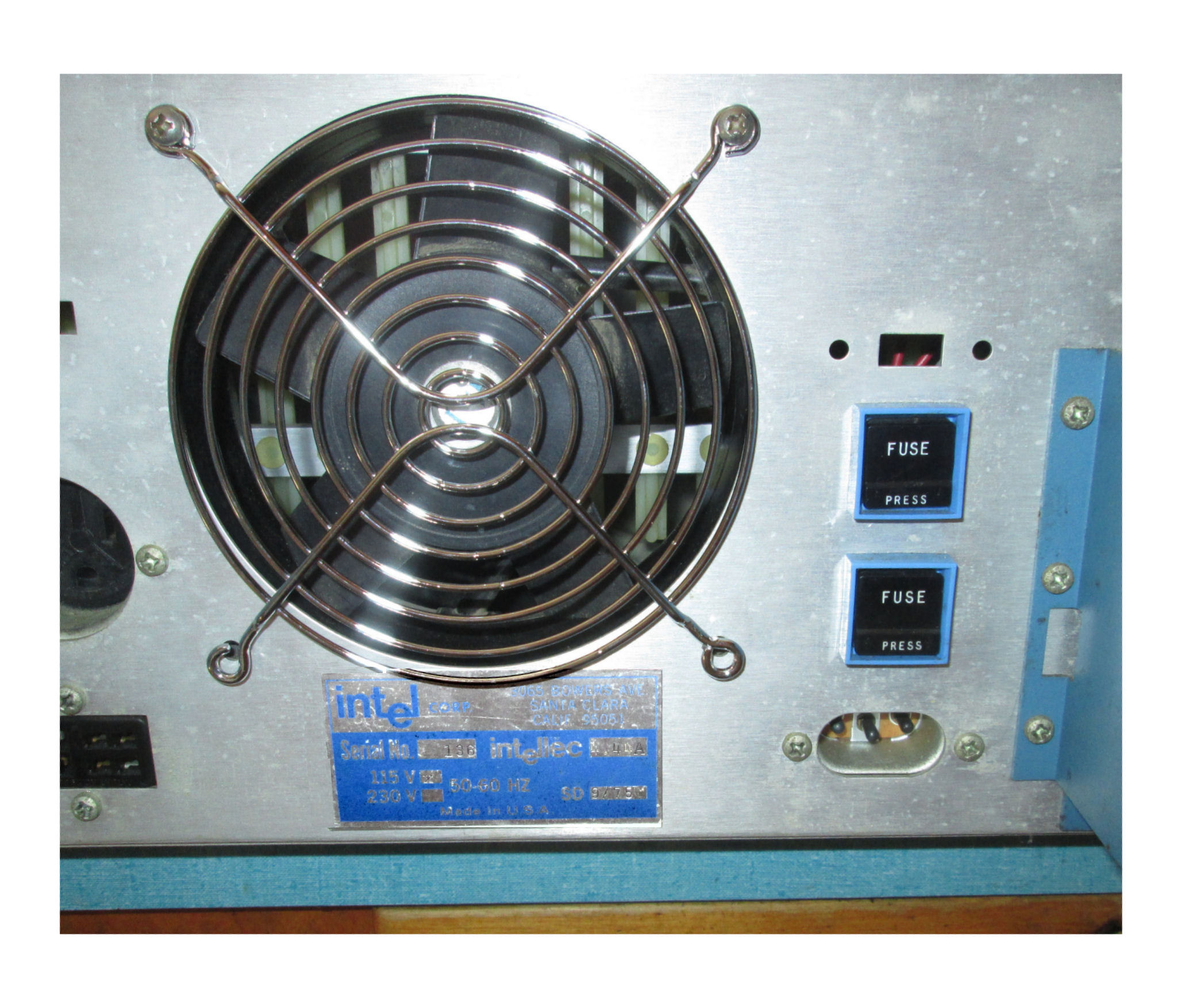
a missing PROM programming socket. The back panel label, shows serial number 136. Apparently the 4/40 was disassembled,
some parts pulled, and stored in some humidity. Photos here show some mold and surface aluminum rust; these are likely
cleanable.
![[Intel MSC 4/40]](4_40_bus_bef.jpg)
![[Intel MSC 4/40]](4_40_chassis_bef.jpg)
![[Intel MSC 4/40]](4_40_block.jpg)
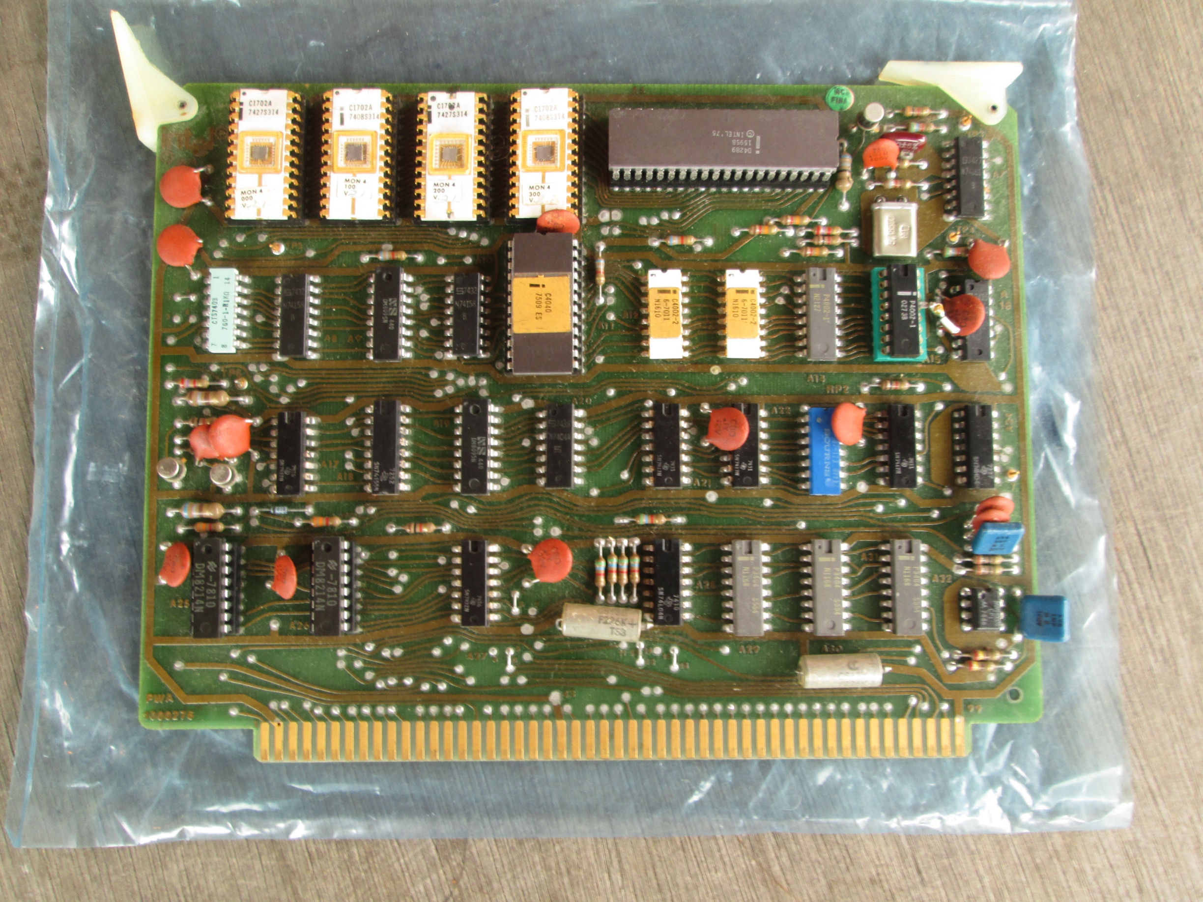
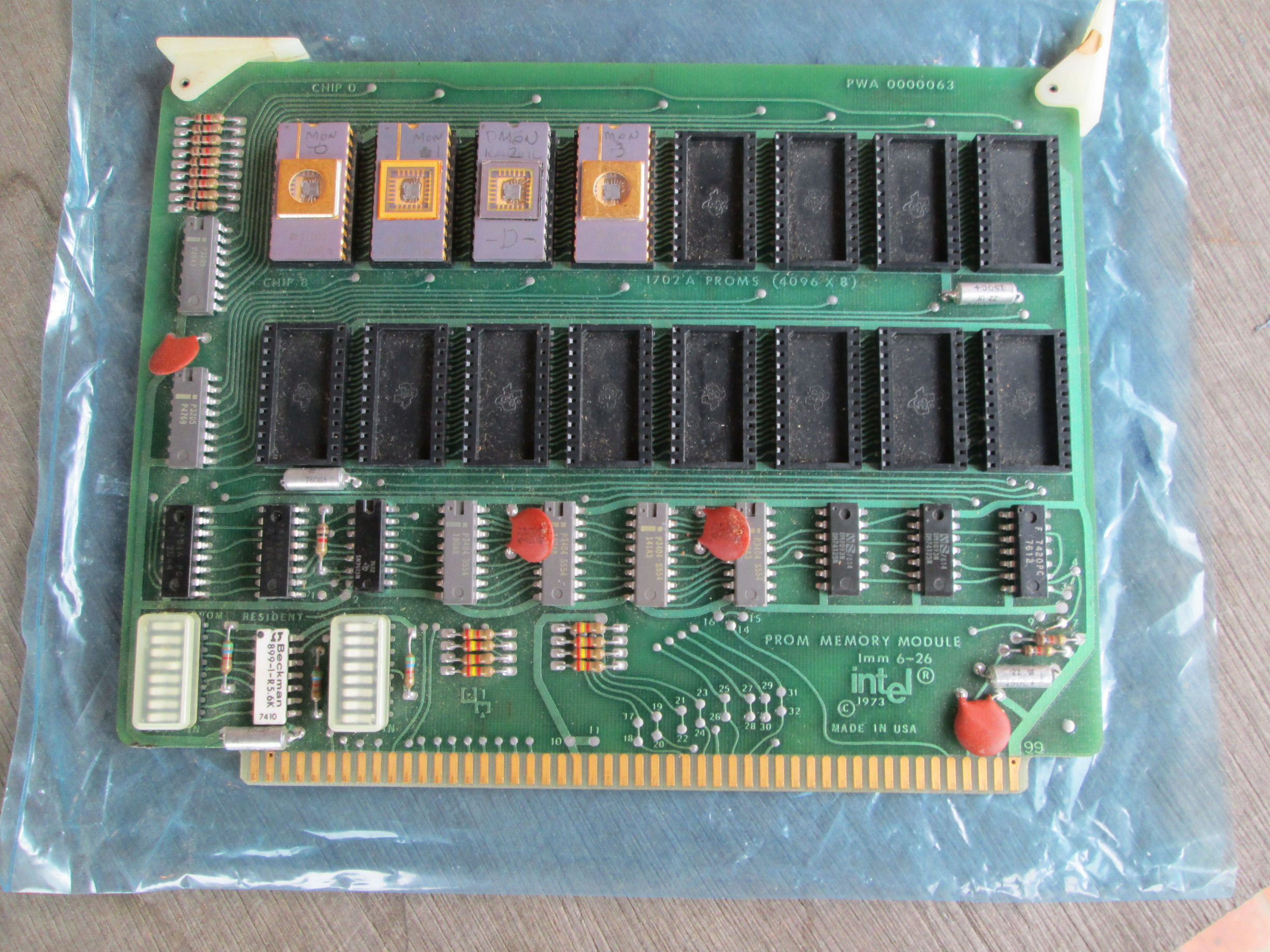
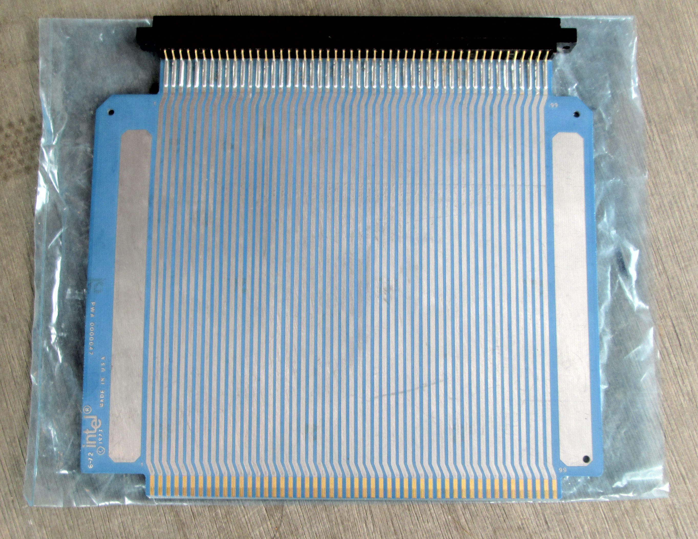
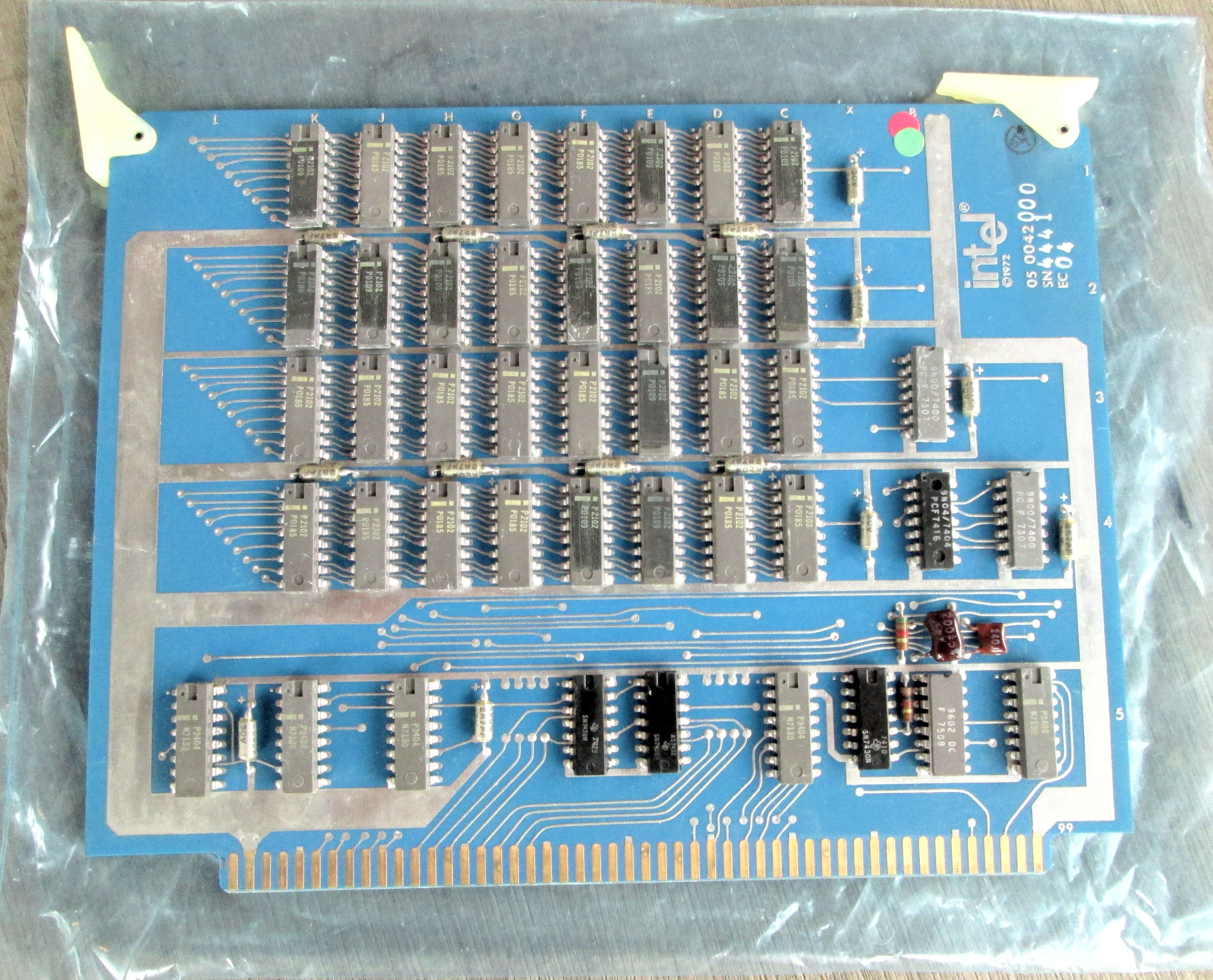
The removable cards of this intellec 4/40 are shown below. The image to the left, shows their functional relationship and physical connections. Some cards are optional, such as I/O and more memory. The 4004 and 4040 seperate program memory in ROM and data memory in RAM. So additional hardware is needed to provide writable program memory in the 4/40 development system.
the 4/40 CPU card with local RAM and ROM PWA M000276.
the 4/40 ROM board, imm6_26 PWA M000063 .
the 4/40 extender card PWA M000047 .
the 4/40 RAM card 05-0042. 4K bytes of 2102's.
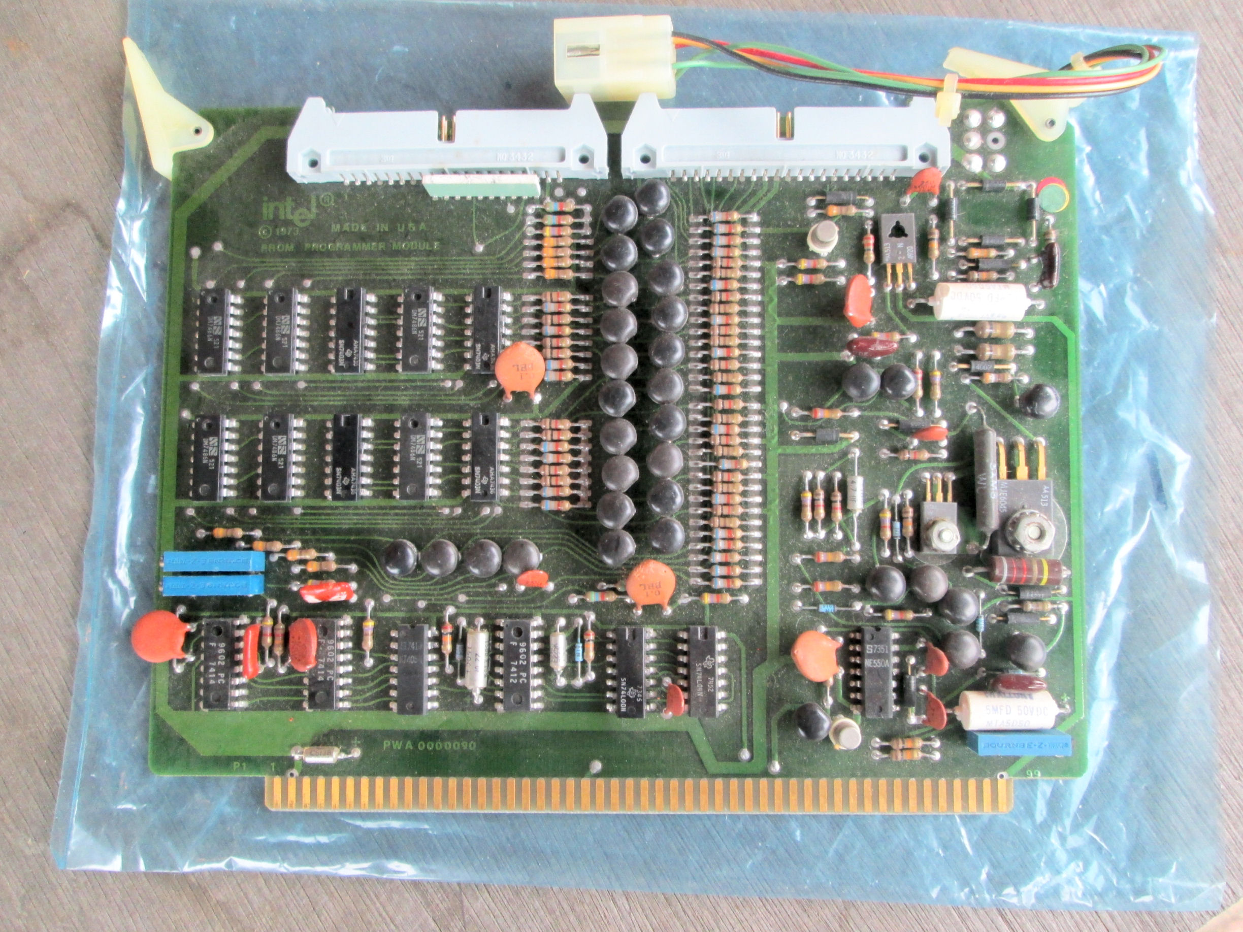
the 4/40 1702 PROM programmer card 0000090.
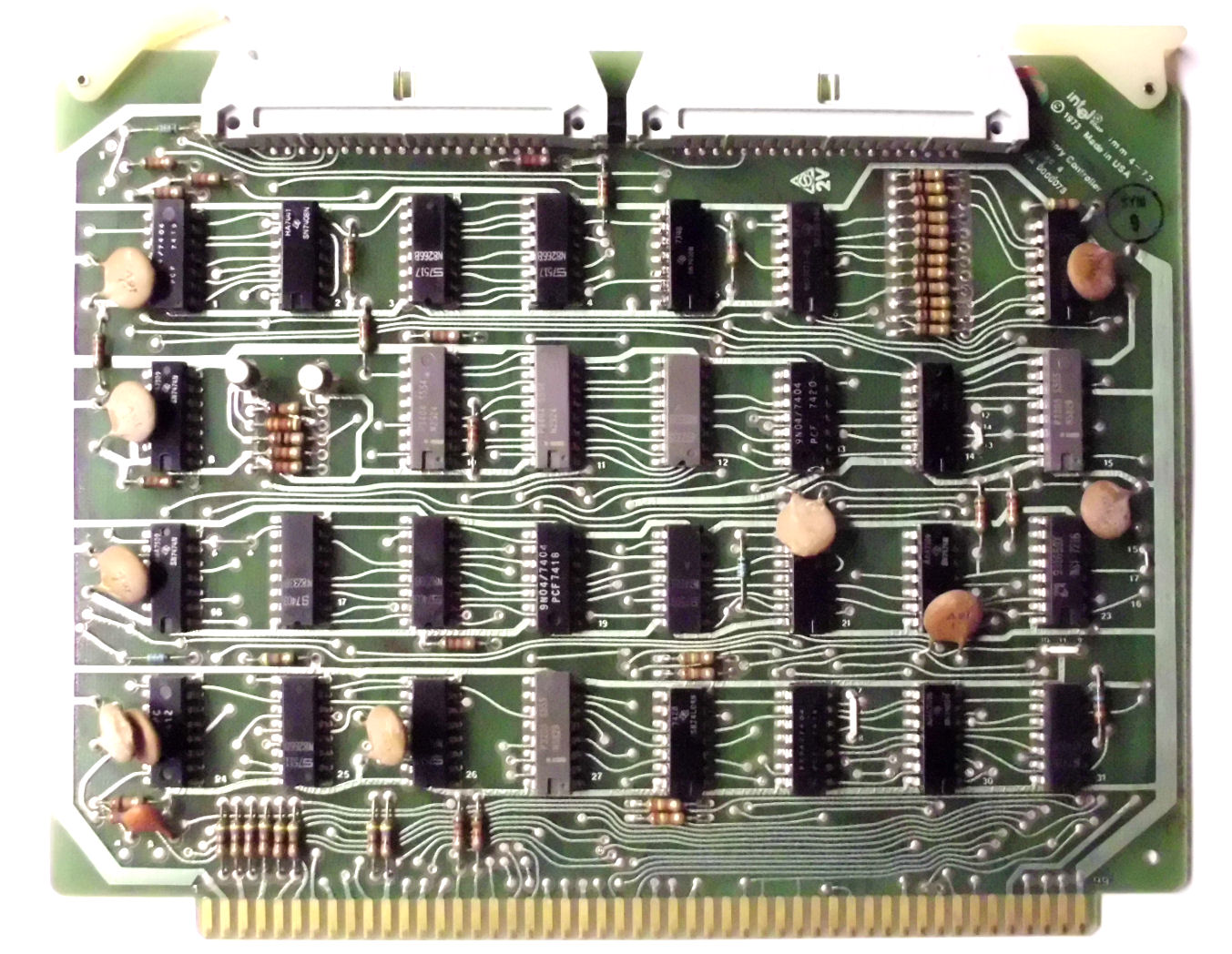
There is a missing "memory control module" board. The User's manual says "The imm 4-72 control module contains
the circuitry required to interface the central processor module to the program RAM module." I have that control
module in my working intellec 4/40 system., it looks like this.
The acquired system included many original Intel 4/40 manuals and 4040 documents. Also listings of Intel Insite library programs. I'll catalog these and scan those not readily available. Many Intel intellec 4 and 4/40 manuals are at bitsavers.org MCS40 and MCS4 folders.
In late 2023 I scanned Hale's partial copy of the Intel Insite Library of programs for the Intel 4004 and 4040. Here's the text-file of the Insite programs by title as taken from an online list of Insite documents. I've marked a few titles as missing from Hale's copy. And Hale didn't have the first sections of the library document, only the sections with actual code. Here's my 300+ page scan of the Insite 4004 4040 library document. Many programs are actually listed out; others were distributed by Intel on paper tape and as seperate documents. If you extract actual assembly code from these pages, let me know and I'll carry that much-smaller source. - Herb Johnson
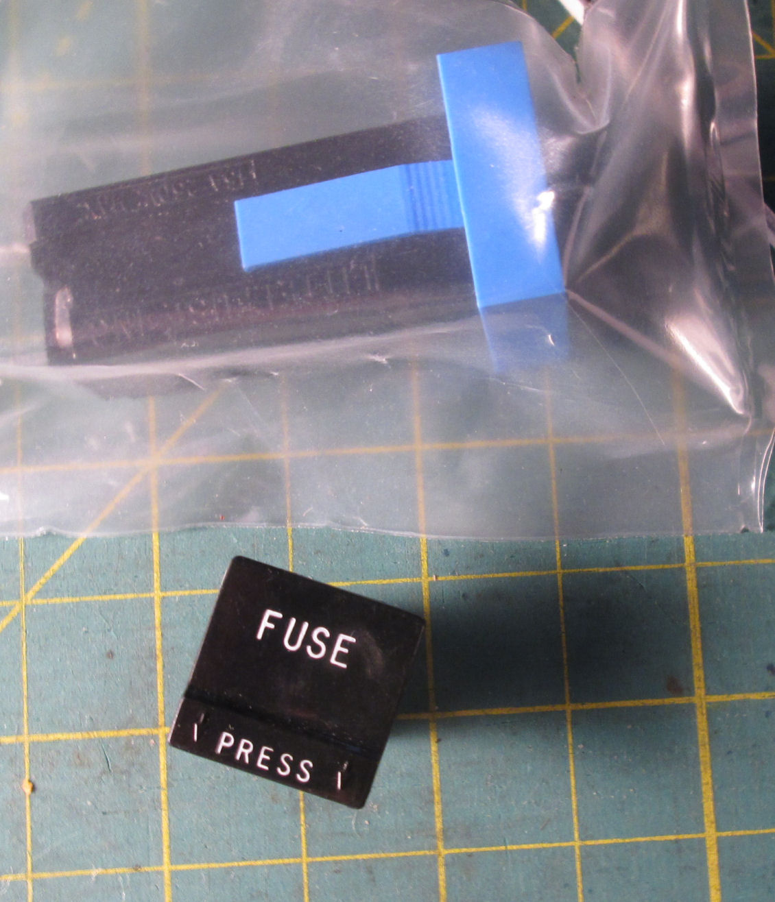
I purchased a black/white fuse cap, and a blue-framed fuse holder.
I've replaced one missing fuse cap (black/white letters), the AC fan, the fan chrome guard.
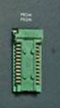
The front panel is missing a (green) ZIF 24-pin socket, on a small PC board. The board is wired to a flat-cable, and goes to the 4/40 programmer module. The cable is documented by Intel. I'll hand-wire a board with socket and cable connector as an expedient replacement. But the board must fit mechanically too. Here's my notes to achive that fit. - Herb Johnson
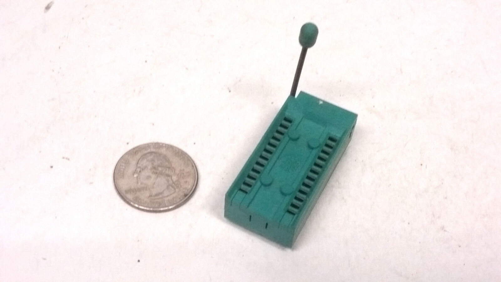
Here's a matching ZIF socket.I found two exact replacments. from different sources.
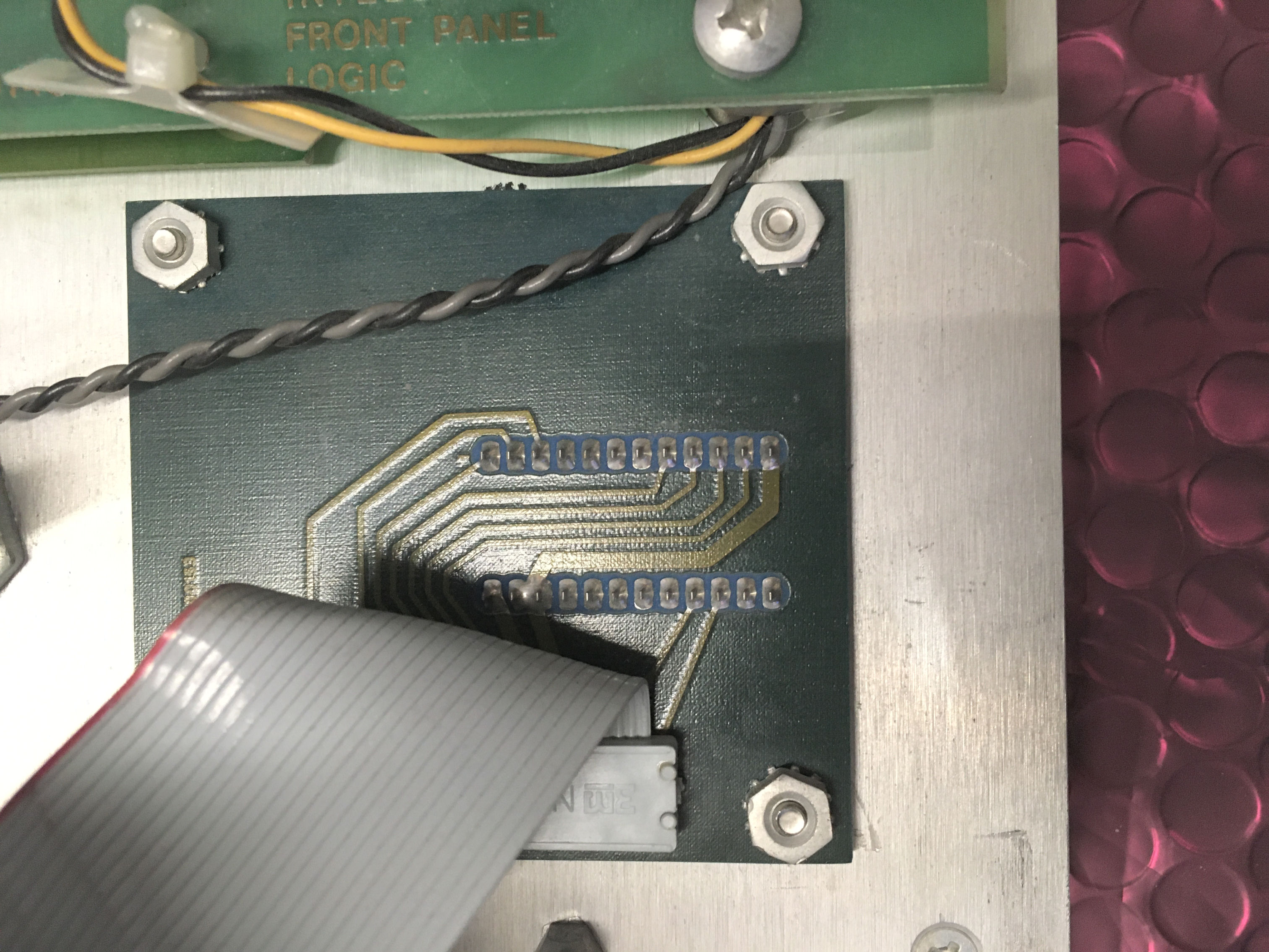
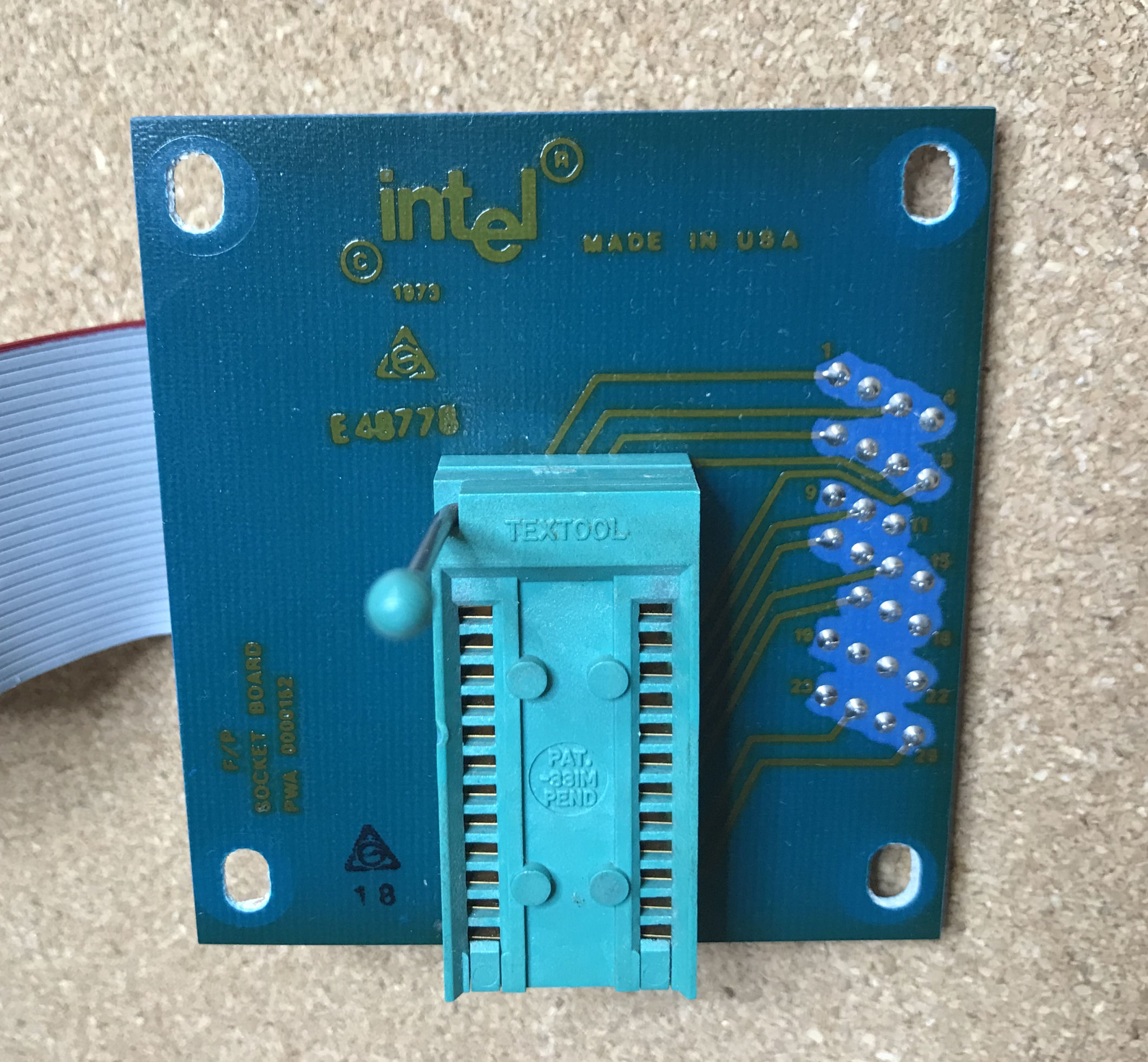
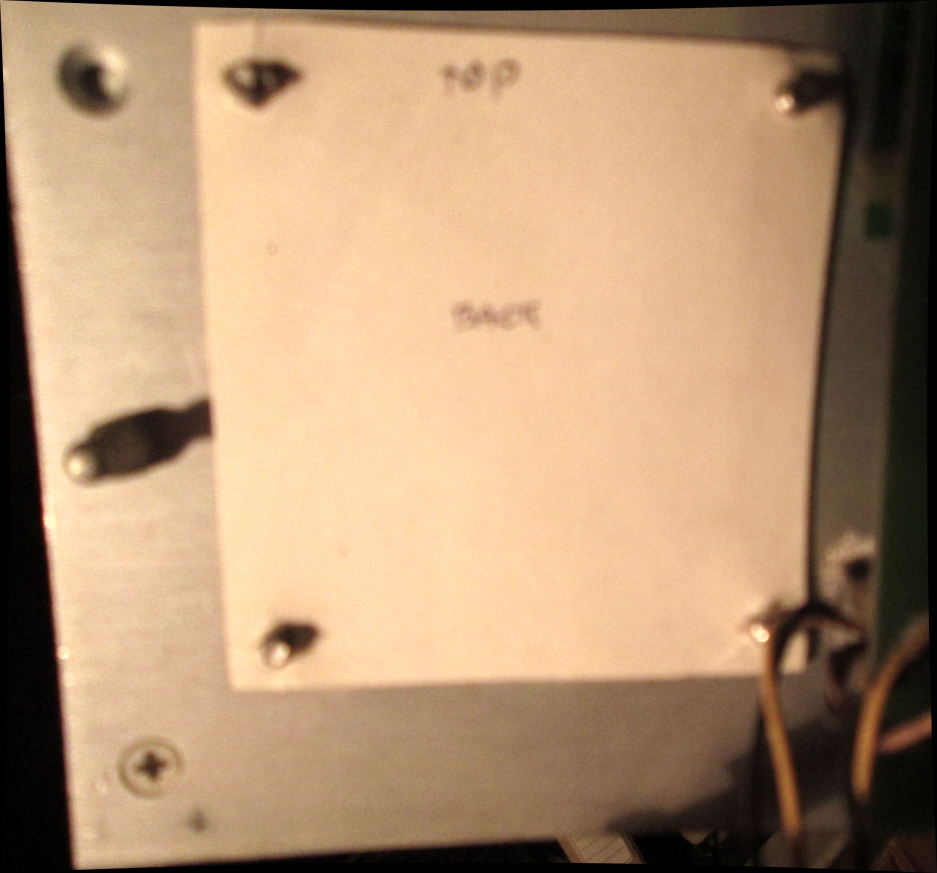
Back view of a 4/40 ZIF socket board & cable, in another system, courtesy Sid.
Sid removed the ZIF "f/p socket board" and provided this front view. Note the mounting screw holes are oversized, so the ZIF socket can be aligned and inserted into the front-panel hole for it. Also note, the PC board is not much bigger than the dimensions of the four mounting screws. The screws are probably 3/32" common screws and nuts.
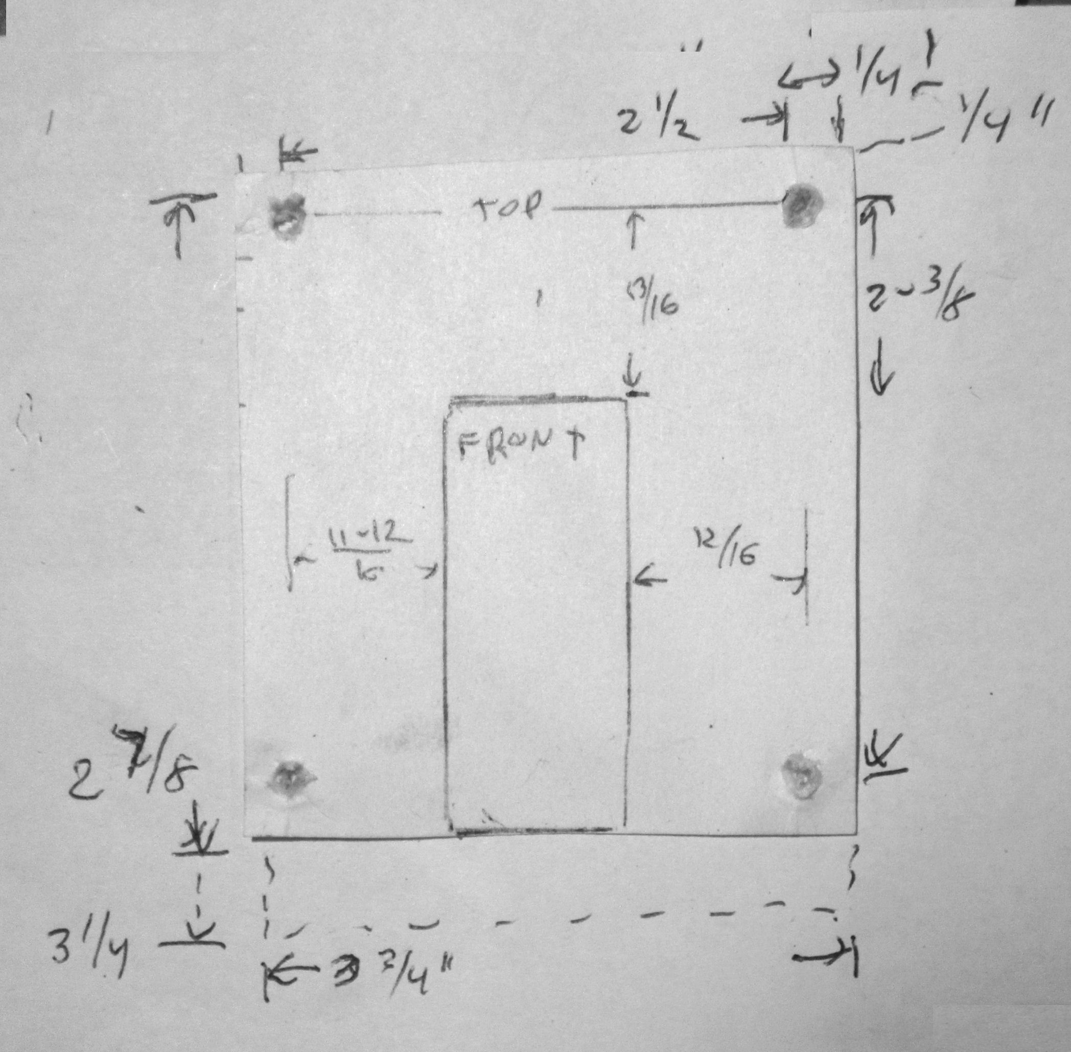
To get an idea of fit for a substitute board, I made a paper template. There's not much space from the screws to the adjacent front panel. Maybe 1/4 inch. Here's a dimensional sketch of the paper template and front panel hole. I cut the paper template a little short.
These results suggest to me, that my sequence of reproduction will be like this. 1) fit the ZIF socket to a perfboard.
2) Fit the perfboard to the back of the front panel, to determine the mounting holes. 3) Drill out the holes with
extensions like the Intel board. 4) Confirm board & socket fit when screwed in. 5) add flat-cable connector and confirm fit again.
6) Then and only then, construct the board wiring between connector and ZIF socket.
While considering intellec breadboards, I considered how or whether to obtain intellec extender boards. Fortunately I have an actual Intel extender, and while I have an Intel breadboard I am loathe to use it! It turns out, S-100 boards (MITS Altair, IMSAI, etc) have common features with intellec boards. (There's no facts I'm aware of to suggest this was deliberate by MITS' Ed Roberts et al.)
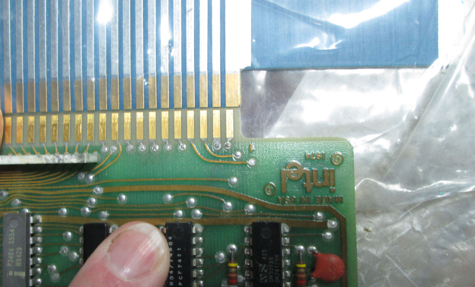
The intellec boards have a 100 pin edge connector on .125 inch centers - just like S-100 (IEEE 696) boards. Of course the S-100 boards are 10 inches wide, the intellect are 8 inches wide. So in principle I could cut up a S-100 extender board or breadboard. However, S-100 boards are FIVE inches tall, while intellec boards are SIX inches tall (excluding edge connector).
However, by good fortune, certain Vector brand extender cards are SEVEN inches tall. So they are cut-down candidates for intellect extenders. So far I've not seen too-tall S-100 protoboards.
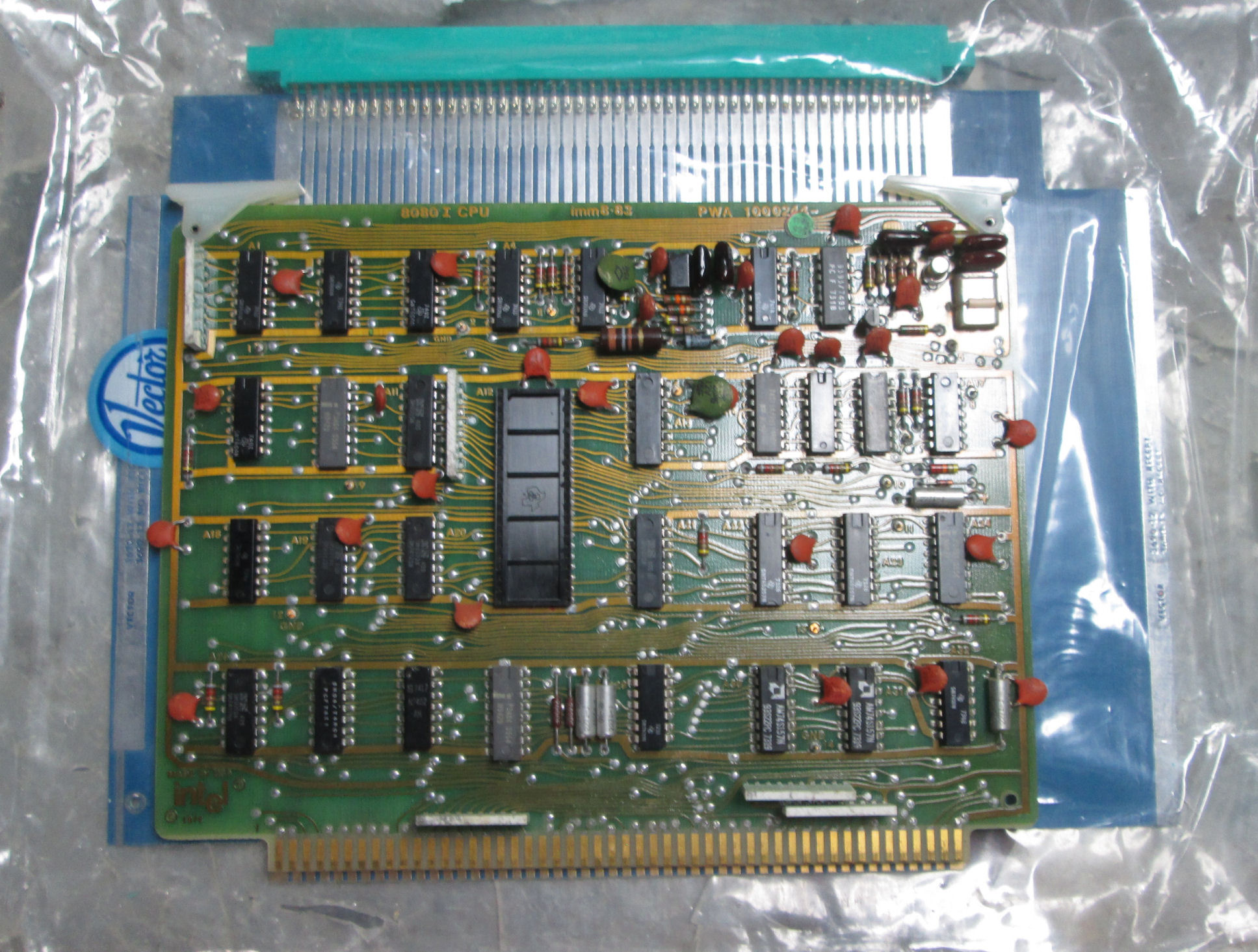
Here's an intellect board, laid upon a Vector S-100 extender board. See the overlap.
Closer inspection of the edge connector confirms compatibility. When cutting the Vector board, I have to pay attention to alignment and fit in the intellec chassis and backplane!
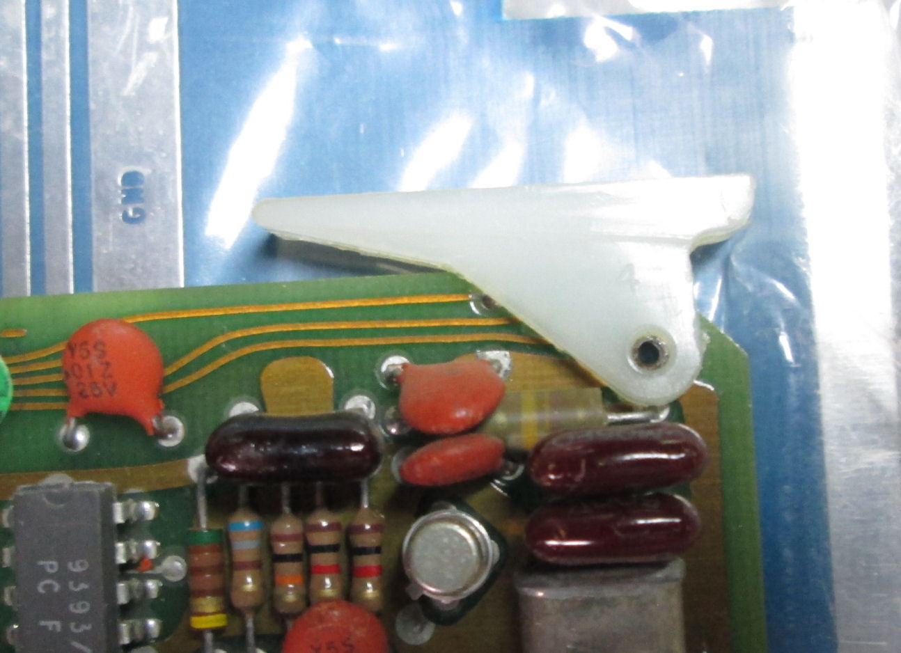
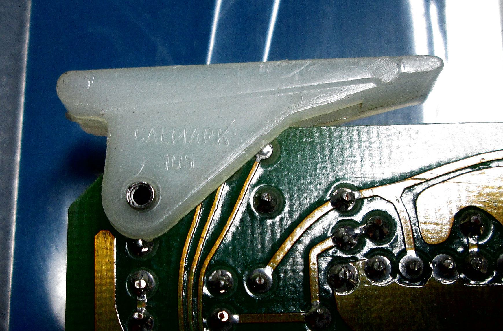
board thickness, ejectors For other reasons, I paid attention to the card ejectors on the intellec board. Here's one ejector and Here's the reverse of the other. Brand and model are "Callmark 105". Web search finds a spec for this! (Oct 2023). I'll compare this to S-100 era ejectors later, and to the intellec 4/40 ejectors. Relevant to mounting ejectors, the Vector extender and the 8080 CPU boards are .065 inches thick, about 1/16 inch. - Herb
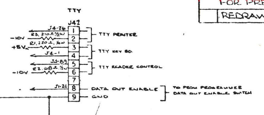
Of course, the intellec 4/40 connected to a Teletype Model ASR33. That provided a paper tape reader and punch, and printing
terminal. Here's a schematic exerpt of the 4040 CPU board's TTY interface. Keep in mind:
this is a 20ma current-loop interface! On my previous 4/40 system, I cobbled up a terminal adapter circuit to a serial
terminal AKA PC serial port. Here's that Web page, look for "interface for serial monitor">. I'll update this note when I get to interfacing this puppy. - Herb
Copyright © 2024 Herb Johnson