![[serial schematic]](ser_minus_sch.jpg)
![[serial signals]](ser_minus_scope.jpg)
Last updated Mar 17 2024, note added Nov 17 2025. Edited by Herb Johnson, (c) Herb Johnson, except for content written by Mark Thomas, Lee Hart and others. Some content from discussions in cosmacelf and in email by Mark Thomas, Lee Hart, Sept-Oct 2013, with perimission.
As of 2014, Revision G and later of the M/S card have a serial interface as part of the Front Panel card. Details about setting up those serial interfaces are discussed on another Web page. And on another Web page, there's a kit described for ROM RAM and serial for Rev-G and later M/S cards. This Web page describes how to add a serial interface to previous versions without that on-board hardware, by replicating most of it on an external board, hand-constructed.
You can also "steal" power from RS-232 to operate the 1802 M/S card! Read this Tech Note to add a few more diodes to do that.
A serial-operated ROM monitor can be installed on Rev G and later M/S cards. If you want one on versions F and earlier, you might install a ROM atop your RAM. This linked Tech Note describes how to add a ROM on top of RAM That page also has some notes about ROM monitor considerations.
Since about Rev H, the serial interface for the front-panel cards was simplified to a TTL interface for TTL/USB serial dongles. This note shows how a Rev L1 serial interface might be patched onto a Rev F or earlier CPU board.- Herb
Note: the circuit described became the serial circuits on Rev G and later front-panel cards. They include a transistor and LED to show incoming recieve activity. Review other revisions of the M/S front-panel card such as Rev G if you want to add that LED display. - Herb]
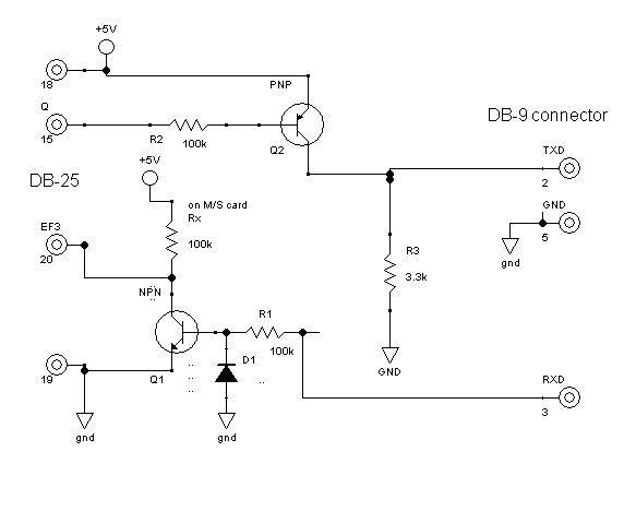
Lee Hart suggested a "simple" RS-232 compatible interface, constructed from a few discrete parts. It's a pair of one-transistor inverters, to produce RXD and TXD at the Membership Card end. The NPN transistor is a 2N3904; the PNP is a 2N3906; but any other NPN and PNP will likely work. Here's a link to the schematic for that interface. It works but the TXD output produces a 5-volt "high" and a 0.6-volt "low"; but RS-232 "likes" a negative level for low.
Lee Hart suggested capturing the terminal's TXD negative idle level through a diode and capacitor, to create a negative supply for the transistor interface's TXD output. In that schematic, (also shown on the left on this Web page) when RXD is negative (connected to terminal's idle TXD line), diode D2 charges the 10uFd capacitor. The 3.3K resistor at the capacitor provides that negative charge to the interface's TXD line (and limits current). That provides the negative low of several volts when the PNP is "off". When the PNP is "on" pulls TXD to 5 volts for the positive high. A noninverting version and an invert-or-not version are described later below.
TTL no-negative note: You should not connect a negative voltage to a TTL input. For a TTL interface (such as to a USB adapter or chip), eliminate the C1 cap.
TTL 3.3V note: If you plan to use a TTL to USB interface, it may be expecting a 3.3V for TXD into it. You may have to add a resistor between the PNP "c" or collector, and the 3.3K resistor to ground; probably on the order of 2.2K. You may have to experiment.
note June 2015: Change the 100K values to 10K. See the noninverting version of this circuit below for details.
C1 as ceramic capacitor: The circuit shown is a variation of the circuit used on the Rev G and later M/S card kit. The capacitor, named C8 in the kit, is normally supplied as a ceramic, nonpolarized part, value 4.7uF to 10uF. If you use an electrolytic or tantalum cap, those are polarized and the positive end should be connected to ground, as shown in this schematic.
To construct, you can mount a DB-25 on a perfboard, to use the M/S card to hold the board, and cable to a DB-9. The discrete parts are wired in between the connector and cable, and their leads soldered up. The DB-9 is wired to match old-school PC's serial port pins. And here's an oscilloscope screen of the interface TXD line (with diode and cap to create a negative TXD signal) at 1200 baud. The center is around ground; the waveform is + or - 4.5 volts, based on the battery driving the Membership card.
![[serial terminal]](ser_minus_scr.jpg)
![[serial perfboard]](ser_minus_bd.jpg)
I rebuilt a Rev F card and built the serial interface with the minus-voltage TXD circuit. That interface
is photographed on the left. I ran it at 300 and 2400 baud, 7 bits, mark parity, one stop bit (7M1). I had to bring out EF3 to the pin 20 on the front-panel DB-25, by cutting grounds from that pin. That is one of the revisions on the Rev G M/S card, which has another version of this serial
interface on the front-panel card. The flatcable on the perfbord goes to a DB-9 connected to a DB9 serial port on an old laptop, running a MS-DOS terminal program. The program running on the Membership Card, is the IDIOT monitor on a ROM and RAM stacked Rev F CPU board. The screen shot on the right shows a ROM dump by the IDIOT monitor.
![[serial schematic]](ser_nonminus_sch.jpg)
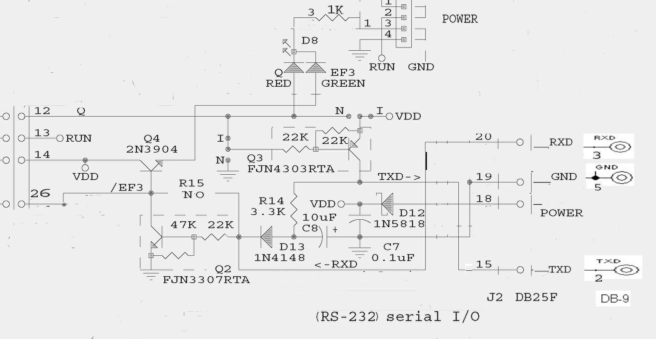
Note: if you want to build a NON-inverting interface, for either transmit or recieve, here's a modified version of the above schematic and parts. The operation is very similar except the transistors are operating as "common-base" which is a non-inverting
logical operation mode. Note that the 100K resistors from the inverting interface are changed to 10K. This is on advice from Lee
Hart, who says these smaller values will speed up or "increase rise/fall time" otherwise due to the capacitiance of components including
cables. The 5.1V Zener on the EF3 input is additional protection against negative RS-232 transmit voltages.
If you need EITHER an "inverted" TXD output OR an option for either,
this later 1802 MS card circuit has jumpers I and N. Together the jumpers flip the PNP transistor from Non-inverting to Inverting signals for TXD.
- Herb, and Lee Hart
[Note: TTL to USB "cables" or adapters are products that change models and versions monthly. Here's
a brief note about them by Lee Hart, I'll try to keep it current. You'll have to find a product that's supported by your
computer's operating system; check with the producers of whatever you purchase for Web links, if you need to find specific drivers
and how to operate those drivers. - Herb.]
[Note: by 2024 or so, the Membership Card front-panel serial operated from TTL/USB dongles. This note shows how a Rev L1 serial interface might be patched onto a Rev F or earlier CPU board.- Herb]
Mark: "For testing I used an el-cheapo CP2104-based USB to TTL serial adapter and a 4093
wired as an inverter to the Q and EF3 lines for a serial port. These are less than $3 each on e-bay, have both
Mac and PC drivers, and might be more desirable for others than [building an RS-232 hardware interface].
I'm tempted to install a faster xtal clock oscillator instead of the
1.8MHz ceramic resonator oscillator. With the stock oscillator, the ROM
serial port auto-baud detection works fine at 1200 bits per second.
[See notes on this page for further discussion.]
parts: 2x 10k 1/8W resistors I also installed a 0.1uf ceramic cap across the 4093 on the +5 and ground pins
and grounded the 4093's unused inputs. I connected Q, EF3, and GND
from [30-pin connector] P1 pins 12, 26, & 30. [Note from Herb: Look at the Rev G schematic or notes on this Web page,
for connections to the DB-25 connector J2.]
Mark Thomas added later: "The CP2104-type USB/TTL converters effectively "invert", just as the MAX232 based TTL to RS232 level converters do. The CP2104 TTL inputs and outputs sit at an idle or "mark", which is +5V (or +3.3V) TTL, with the start bit and active data bits going to a "space" 0V TTL."
"As best as I can tell, the general standard for TTL serial data is mark=+5V and space=0V, while the RS232 standard levels are a mark=-12V and space=+12V."
"I have been using CP2104 based TTL/USB converters from e-bay with success...now with rev-G board, no need for the additional inverter chip as shown breadboarded in my photos. I got them from [an] e-bay seller for $2.75 each, but there seem to be numerous sources of nearly identical CP2104 based converters out there."
The MAX3232 requires a real terminal, or a PC/Mac with a serial port. The
TTL/USB adapter requires appropriate drivers for PC or Mac use. [Look for links to the manufacturer's
drivers, on the Web pages where these products are sold, or track down the chip manufacturers. - Herb] I just posted more pictures at cosmacelf (once approved by the moderator), detailing
completion of the project by installing it in a small project case case,
with a home-made Lexan front panel, rechargeable batteries, a MAX232
DE-9 RS-232 interface, and charger/regulator electronics on some perfboard
the size of a postage stamp. This ended up being a tighter fit than
I expected, but with care it all fit!
The MAX232 card still required a logic inverter (to remain compatible with
the unmodified elf2k ROM), so I glued a 4093 upside down on top of the
surface mount MAX232. The interface cards were qty 5 for $12 + $2 shipping
on e-bay from China.
I used a [several volt DC supply and a] LP2950CZ-5.0 low-dropout 100ma 5vdc regulator and the necessary
caps, diodes, and resistor, to power the membership card at 5VDC, and
provide a current limited (~7.5V) trickle charge to the 6 AA cells. This
is not the ideal way to charge NiMh or even NiCd batteries, but I'm sure
the cells will last for years anyway. I guess I should post schematics for
the ROM wiring, the serial interface module, and the regulator/charger
module. This charges the batteries and/or powers the membership card
from a 9VDC-12VDC wall wart.
The plastic case (270-1805), six NiMh AA batteries, and the DPDT mini
toggle switch came from Radio Shack. The Lexan for the front came from
Home Depot. I also ended up mounting a small SPST switch above the DC
power jack, after having odd results getting the membership card to
consistently sleep at <1ma.
I wanted it to be battery powered and self contained. And the serial port
provides an easy way to load and even develop software, thanks to the awesome
collection of utilities on the 32K elf2k ROM chip that sits piggy-back on
the membership card's 32K SRAM.
- Mark
This page and edited content is copyright Herb Johnson (c) 2025.
Contact Herb at www.retrotechnology.com, an email address is available on that page..
Mark Thomas: USB to TTL, mark and space conditions
USB cables or adapters
![[serial schematic]](mem_romstack_serial.jpg)
1x 4093 quad 2-input NAND gate (wired as a level inverter)
1x either a CP2104 TTL/USB converter or a MAX3232 TTL/RS232 converter.
(These are less than $5 on e-bay.)
mark and space line conditions
        RS232    TTL (such as for a MAX232)    TTL for CP2104-I/O
        ------   --------------------------    ------------------
mark    -12V  <=> +5V                        =  +5V or +3.3V
space   +12V  <=>  0V                         =  0V

serial data as an oscilloscope display:

mark
-----|      --         |---------
     |st 0 |1 |2 etc...|
     |--|--|  |--......|
space

Note: "mark" is not always a positive voltage, and not all data bits are
active or in "space" condition, such as bit 1 above.
Mark Thomas' MAX232 interface
Contact information for Herb Johnson:
Herb Johnson
New Jersey, USA
To email @ me, see see my home Web page.