![[rev l CPU]](mem_revL_cpu_aug22.jpg)
![[rev L front panel]](mem_revL_fp_aug22.jpg)
Page last updated Mar 26 2024.This is the support page for the Rev L CPU / Rev L front-panel 1802 Membership Cards. The Rev L CPU board entered distribution as of July 1 2022, until a Rev L1 CPU (minor component & board changes) went into distribution on Mar 5 2024. The Rev L front-panel entered distribution as of May 1 2022.
The CPU now supports a "jump-on-reset" to briefly execute the start of high-memory ROM at 0000H to force a jump to high memory. The Front Panel now includes a six-digit display with ROM decode for alpha/numeric 7-segment display, bits decoded with a 2716-type ROM. The DB-25 I/O connector on previous front-panel versions was removed to accomodate the Rev L display; use the 30-pin bus instead for those signals.
For those familar with previous 1802 Membership Cards, Rev K4L was in distribution with the Rev K4 CPU and Rev L front panel. see the Rev K4L Web page for details. For prior versions, see the Chronological section for links to pages and their documents.
This Web page contains MANY Web links with support and use information; but there's more background about design changes on previous version support pages. Links to order and for more information are below.
The photo on the left is of the bare Rev L CPU board, photo by Herb Johnson. The photo on the right is the Rev L Front Panel 1802 Membership Card, photo by Herb Johnson.
"For those just tuning in, the Membership Card Kit is a reproduction of the original Popular Electronics COSMAC Elf computer, but shrunk to fit in an Altoids tin! It works the same, and runs the same software." - Lee Hart, developer.
How to order: Order the Membership Card via links from the 1802 Membership Card home Web page. The page has links to current and previous 1802 Membership Card version pages. It also has links to 1802 history, testing, hardware, software, and more.
Product documents
A quality kit for the beginner or vintage builder
Rev L features and options
Initial testing and programming
Rev L board descriptions
Engineering & Change Data
Hardware and software and notes about them
Errors, corrections, mods
Chronology of Membership Card products & support Web pages
Prices, ordering, contact
Pages edited by Herb Johnson, (c) 2022 Herb Johnson, except for content created by Lee Hart and others. To report errors on this page, contact Herb at www.retrotechnology.com, an email address is on that page. - Herb Johnson
![[parts kit]](mem_j_kit.jpg)
![[Rev L front panel]](1802fp_l.jpg)
Documentation Rev L CPU and Rev L front panel:
The Rev L CPU / Rev L front panel manual Feb 14 2024.
See the Engineering section for accumulated Rev L changes.
To operate all six digits of the Rev L front panel, see this interrupt code.
See the Recent History section for links to these and earlier Web pages with documents.
Here's the link to the 2019 1802 cheat sheet . Gives the 1802 instruction set, Rev J connections.
On the left is a Rev J kit parts from May 2018; the Rev J & K parts kits look much the same. On the right, is an assembled Rev L front panel, by Lee Hart.
![[edge view]](mem_revI_build_2.jpg)
Small size, ordinary components, "how to assemble" manual for hands-on building. The front panel and CPU boards stack to fit in an Altoids tin. (Rev I stack shown.) The front panel cover board (optional) fits over the Altoids lid.
Only readily-available electronic parts are used (except the 1802) and are part of the kit. Most parts are from the 1970's "ELF" era. All thru-hole parts (not surface mount), for easy hand assembly. Assembly manual guides construction, part by part, with testing and debug information.
Quality printed-circuit board, easy to see, build and repair:
- quality USA-made PC board material, 1 oz. copper, wide 15 mil traces
- key chips tested before distribution to avoid counterfits
- white, legible "silk screen" text to identify parts and pin functions
- 60 mil large pads, 40 mil holes to fit larger pins or pin-socket inserts
- large holes and pads are easier to desolder misplaced parts without damage
- gives a 70's look to a 1976 processor kit
"On occasion, customers have put parts in the wrong places. They commented [to me] that they were amazed they could remove them without damaging the PCB." - Lee Hart June 2021
Run with or without a PC. For the full product, no PC, external hardware, or any onboard program, are required for use. Front-panel runs, halt, loads by toggling switches. LED binary display. These are same features as the classic COSMAC ELF; plus RAM, ROM and I/O options as described here. For the CPU alone, it can be operated by a serial link which controls a ROM monitor or a ROMmed BASIC. Or you can put your own programs in ROM, or download them into RAM via a ROM monitor.
8-bit input and output ports The CPU and Front Panel boards have a common 30-pin header. It supports 8-bit data in and out; power and ground; 1802 LOAD and RUN; and serial. These lines are also used by the front panel to operate the 1802 in "load" mode. The data ports provide toggle-in and LED-out ports. With a Front Panel atop the CPU board, you could add another 30-pin header to the Front Panel to access the 30-pin signals. Some use those signals to load the RAM with a microcontroller and run without a ROM or serial connections. Check earlier version's documents for details and ways to operate these Membership Card signals.
serial interface operation via EF3 and Q with a TTL serial interface. A two-color LED shows serial activity on Q and EF3. Serial operation requires a ROM or program to support a "software UART" and to interact with the serial user. The TTL connector is also the +5V power connector and can be compatible with some USB-to-serial adapter cables and boards. Serial and RS-232 features were discussed in more detail on the Rev I Web page's "Engineering" notes.
stable clock frequency with ceramic resonator. Rev K4 is sold with a 4 MHz resonator. Previous versions included a 1.7Mhz resonator.
Low-power standby, nonvolitile RAM: Separating the CPU board from the Front Panel, or disconnecting the power connector, will put the CPU board into a "standby state", program halted and RAM contents saved by the supercapacitor. Save time is hours to days depending. "With the supercap, I can load a testing program into RAM, test an 1802, remove power, put in the next 1802, and power up. The test program is still in RAM and runs." - Lee Hart
RAM and ROM on one CPU board The K4 kit comes with a .3-inch narrow RAM chip. A ROM can be installed above the narrow RAM. You can run the CPU board only, with a USB to TTL serial adapter on connector P5, and a ROM monitor with serial terminal support. Assembly and operation is described in the K4 manual.
Add a ROM monitor or BASIC: Lee Hart offers ROM files or ROMS for ROM BASIC and / or an 1802 ROM monitor, or a "diskless" operating ROM. See these on Lee Hart's sales Web page. Other monitors or programs, from Lee Hart or others, can be run from your own ROM or from RAM, see the software notes below.
To order: Refer to the Membership Card home page for the current ordering status. An email address and Web link takes you to developer Lee Hart for ordering and contact.
The kit manual will have test programs and debug information; ROM monitors and BASIC ROMs are also available. Also, see this document on Testing the 1802 Membership Card with small toggle-in programs. Basic operations of the front panel are described. There's more links about testing and use, under "features" on this Web page. Other links are to testing hardware Web pages and testing software Web pages are on listed on the home Web page. - Herb Johnson
The 1802 Membership card set, consists of a CPU board stacked on a Front Panel board, with an optional Cover Board atop the toggles. Or, you can run the CPU board alone. Also, you can buy a prototyping board for your own circuits. You can buy ROMs for a monitor or for BASIC; or burn your own ROMs from images provided. You can buy the boards, or a kit with boards and parts; or partial kits. And, you can buy a Cover Board, a circuit board to cover the switches and lights of the Front Panel card. These are all sized to fit an Altoids tin box. All boards (except the cover) accomodate the CPU's 30-pin expansion connector, which is also a data and control interface to and from other TTL-class devices or microcontrollers.
![[Rev L CPU]](revL_cpu_soc2.jpg)
Rev L CPU bare board on left; right is an assembled Rev L CPU (IC sockets not in full kit). See the Engineering section for specific changes. Look in particular for notes on a Rev L1 modification in Feb 2024.
- 1802 microprocessor (option for 1804/5/6 which have no load mode).
- .6-inch 24-pin socket for 2K to 32K byte-wide RAM or ROM, selected by P2 & P3 jumpers
- also .3-inch 24-pin socket under ROM/RAM for narrow SRAM or ROM.
- supercapacitor to maintain RAM contents with power disconnected or /ON asserted
- HI/LO jumper select on board ROM/RAM for high or low 32K address space
- NEW "Run-on-jump" circuit to briefly move ROM "low" to execute a jump to high memory.
- board cuts to select U8 as narrow ROM not RAM
- optional +5 volt power input at DB-25 pin 18 w/diode protection (jumper selected)
- NEW 6-pin serial/power connector P5 to USB/power dongle to use CPU stand-alone
- NEW Rev L1 adjust for speed of RAM, this note
- diode to /CLEAR for power-on clear
- ceramic resonator for stable clock, now 4.0 MHz in full kit
- the usual 1802 I/O bits (Q, EF1-EF4, INT, etc.)
- IN/OUT4, control, serial and power brought out to a 30-pin header (pins labeled)
- size: 3.5" x 2.125"
- power: 3-6vdc at several mA, less current at lower clock speeds, CMOS parts
Rev L front panel bare board component side on right, as built by Lee Hart on left. Note: the standard Rev L kit is sold with *two* 7-segment displays. If you want all six, ask Lee Hart for details. See the "mods" notes for details.)
- plugs onto the 30-pin connector of the Membership Card CPU board
- no PC, external hardware, or any onboard program, are required for front-panel use.
- read/write memory, run/clear, run/load toggle switches
- LEDs and toggles provides the Elf front panel interface as follows:
-- 8 data output LEDs (memory reads and OUT4)
-- in/out LED to display serial activity
-- 1 input and EF4 pushbutton to load front-panel switch data
-- 8 data input toggle switches (memory writes and INP4)
-- 6-pin serial/power connector P4 for single connector to USB/power dongle
-- NEW 7-segment display:
---- hardware mode displays memory or OUT4 as two hex digits (two digits standard with kit)
---- software mode displays six-character ASCII messages with appropriate software
-- NEW hardware timer for interrupts to display six hex/ASCII messages
---- See these linked notes for discussion
---- don't install interrupt jumper P9 or transistor Q6 if there's no interrupt software.
---- See this interrupt code as an example.
-- "This new Front Panel is interchangeable upon all my previous 1802MC CPU boards." - Lee Hart
-- IN/OUT4 8 bit ports, control, serial and power brought out to a 30-pin header (pins labled)
- size: 3.5" x 2.125"
- low power consumption: 0.25mA standby, plus about 1mA for each LED on
- interchangeable with all previous 1802MC CPU and Front Panels cards

6-pin serial/power connector
- RX/TX GND and +5 volts compatible with some USB-to-serial adapters
- adds "idle" signal, could be connected to serial (TTL level) RTS line or a toggle switch.
- one pin is removed, to key the cable connector so to avoid a reversed connection.
![[cover card]](mem_revL_cover_aug22.jpg)
The Membership Card Cover Board is a *green* PC board to cover the Altoids lid and mounts on the Front Panel board. The board has holes for the switches, LEDs, power/serial connector, and the hex display (or the earlier front-panel DB-25 connector). There's silkscreened white labels and a tinned copper shield on the back. Cut a large rough rectangular hole in the Altoids box, and epoxy this board to the top to provide a neat finished front panel.
![[protoboard]](mship_proto_1.jpg)
The Membership Card Protoboard is a PC board for prototyping and development. It mounts on the CPU board instead of, or potentially underneath, the Front Panel board. It's sold
seperately from the 1802 M/S Card kit or board set. See this Protoboard Web page for more details.
Lee Hart provides ROM images for monitors, BASIC and other programs. From mid-2021 Lee offers a ROM and RAM kit. Details and documents will be on Lee Hart's ordering Web page, get there by links from the 1802 Membership Card home Web page. Currently the ROMs available as images and/or as prepared ROMS include:
MCSMP20 series of ROM monitors with BASIC3;
Tiny BASIC;
Chuck Yakym's MCSMP Super Monitor plus BASIC3;
Mike Riley's Elf/OS diskless ROM with many programs.
Go to my Membership Card home page for a Web link, to developer Lee Hart for ordering and contact.
The Rev L/L1 is a major redesign from Rev K. Notes were developed by Lee Hart and edited or discussed
with Herb Johnson. Changes to date are:
A Rev L1 CPU change to CD4013 and memory timing;
"Jump on run";
six-digit display;
I/O decoding, end of DB-25
memory decoding.
Rev L1 CPU, Tech Note on speed of CD4013 TPB decode and RAM access, hardware fixesIn the rev L1 revision of the 1802MC CPU, Lee Hart provides an option to adjust the timing of RAM and IO4 decode. See the Membership Card Manual rev L1 for details for that kit. This Tech Note provides guidance for that option and for reworking 1802 MC's to use slower or faster RAM and slower or faster 4013 flip-flops, depending on component age. To modify the Rev L to include L1 changes, see these mod notes. - Herb Johnson
Jump-on-run, BRIEFLY: A transistor Q1 is used to switch an R/C circuit R9/C6 from Reset,
to temporarily re-address the ROM normally at 8000H, to execute the first few bytes of the ROM at 0000H which is
the 1802 reset address. To operate the jump, the "IN" button must be held down while the CLEAR is toggled from RUN
to RESET and back to RUN again. Proper operation and execution depends on the clock speed of the 1802 and run time
of the reset program. These are determined by the 4MHz ceramic resonator, and the 1802 instructions namely DIS and JMP. The time of the R/C circuit is adjusted by changing the capacitor C6.See "Jump on run" notes for details.
In June 2023, Lee Hart explained the run-on-jump operation this way:
"To use the power-on-jump to 8000h feature of the Membership Card rev.L, start with the WAIT and CLEAR switches both up (the RUN position), and with the read/write switch in the RAM position.
1. Flip the CLEAR switch down. (Leave the WAIT switch up).
2. Hold down the IN button,and at the same time
3. flip the CLEAR switch up (RUN position).
4. Release the IN button." - Lee Hart
The MC will execute whatever is in ROM at the "bottom" of ROM, the first bytes of ROM, as if the ROM is located at 0000H. Typically the 1802 instructions would be a "long jump to 8000-something". Then the 1802 will execute the code in the ROM, just after these first bytes, with the ROM subsequently addressed in high memory at 8000H-something. - Herb Johnson
ROM code for run-on-jump, BRIEFLY: The delay provided by the 0.1uF capacitor [in the address circuit] is plenty of time for the 1802 to do its 9-cycle init, then the DIS, then the LBR instruction, even with a 1.8 MHz clock. [It turns out, the Chuck Yakyam monitor offered by Lee Hart starts with the following instructions: DIS, 00H, LBR to high memory.] The bigger risk is that the delay might be too *long*. It needs to time out before the first attempt to read/write something in low memory. Chuck's programs are fine here as well. His programs take a long LONG time to get around to using low memory. - Lee Hart, April 2022
two/six-digit display, May - Aug 2022, BRIEFLY:
The rev.L Front Panel adds places for six 7-segment LED digits. Two digits are provided with the basic kit. "I didn't want to increase the price of the kit; so it comes with 2 digits so I could keep the price down. The digits are about $1.50 each. Extra digits are available from me or [as parts] from various distributors." - Lee Hart June 29 2022.
A 27C16 EPROM is programmed to display a byte from memory or the OUT4 port as two hexadecimal digits; no software is required for this operation - just like the original Elf computers with their HP or TI hex-to-7seg displays. - Lee Hart
To use six 7-segment digits, a scan clock and counter are provided. The scan clock generates an interrupt every 2.5 msec if transistor Q6 is added. The interrupt informs an 1802 interrupt handler to output data for the next digit. When the 6th digit is reached, EF2 goes low to inform the interrupt handler to start over at the 1st digit. The EPROM has both hex- and ASCII- character sets, which can be selected with a HEX/TXT jumper. In HEX mode and without interrupt software, the EPROM supports a 2-hex-digit
display of the value on the OUT4 port.
Here's further discussion about the Rev L hex-display. See a note below about "Display interrupt disable" for testing a display handler. For example code, see this interrupt code.
Lee describes the displays: "[7-segment] high-efficiency red 0.32" DIP, Lumex LDS-A3504RD-SI; 13 mcd at 10ma per segment. They light up nicely on the 1ma that my multimeter diode test setting provides.Digikey and Mouser also have them in green; maybe other colors as well. Lumex, Rohm, Stanley, and maybe others make 7-seg LEDs in this format." - Lee
May 4 2022: red lens For a red display cover for the Cover Card, Paul Schmidt wrote in cosmacelf groups.io: "Lee, PRD Plastics has some small red lexan windows, Digikey stocks them ..." Lee Hart replied: "Aha; thanks Paul! It looks like Digikey #PRD180R-ND [PDR 6201030, Red Lens for 1.8" Bezel] would work. It's red, 1.87" x 0.87". The DB25 holes [on the front-panel card] are 1.85" apart, and so just catch the width. The height is just right to cover the obsolete "PC SERIAL/PARALLEL PORT" text. About $2 each, or half that for 100."
I/O decoding by U4A, end of DB-25, BRIEFLY:
Y0 is active low, when 1) the jumpered N's are not active AND 2) WAIT is active-low. So asserting /WAIT pulls down YO and the G2 line to the input buffer, allowing the input toggles to be read.
Y3 is active low, when 1) the jumpered N's are active AND 2) WAIT is inactive (/WAIT is not asserted). Y3 active low also pulls down G3 to the input buffer. The diode D16 and resistor R2 wire-OR the Y0 and Y3 outputs.
Y2 is active low, when 1) /WAIT is inactive (high) AND 2) the jumpered N's are inactive. So Y2 is low
most of the time. It's high when the jumpered N's are active. So on the jumpered-N IN or OUT, Y2 goes
high. Y2 is the D input to flip-flop U5A. TPB clocks the D state to Q, unless /MRD is low. So the
net result is that on OUT for the jumpered port, "OUT 4" the Q-output is clocked low by TPB. OUT4
loads the output latch U7.
"[Previous versions of the 1802 Front Panel had a DB-25 connector to the CPU's input and output I/O ports, 1802 signals, serial signals. But] all the signals that were on the DB25 are still on the 30-pin header. The Front Panel [PC board] has two rows of holes. So you can install a 30-pin male header on the Front Panel to provide access to them." - Lee Hart, April 2022
I read the memory addressing on U4B as: Y3 or "HI" is active low on TPB+A15; Y2 or "LO" is active low on TBP+/A15. So the decoder is essentially two AND gates. As Lee Hart pointed out, disabling RAM and ROM during non-TPB, saves a little power. Lee responded with: "Yes. Without this fix, the board draws 40-60ma with a 32K skinny RAM at org 0. With it, this drops to 5-10ma." While the narrow RAMS are CMOS memory, they were designed to run very fast so they have high-current data
line drivers to switch quickly. - Herb
Various non-critical components in the kit, may have different values from the current or previous manual. Typically these are like pull-up resistors, or the super-capacitor, transistors, or some I/O logic chips. Look at the Engineering Changes for design changes. In this section I try to document errors and solutions, or
useful changes after/during construction which are optional. Previous revisions each have their Web pages with manuals and other changes. - Herb Johnson
CPU L changes to Rev L1, March 2024:
The Engineering Notes describe the change from CPU Rev L to
Rev L1, due to issues with addressing slow-speed EPROMs. Here's notes on how to mod
your Rev L CPU board to replicate the Rev L1 changes. - Herb.
Lee Hart: "If you ADD a 32k Expansion EPROM, and it happens to be a slow part (or a slow part re-labeled as a fast part), then it may not work. If so, use one of these solutions: Aug 31 2022: transistor changes Due to supply shortages, the FNJ3305's were changed to FNJ3304's. These transistors include internal "bias" resistors. One resistor R17 was changed as a result. See the schematic and manual for the date appropriate to your kit's purchase. - Herb Johnson
Aug 9 2022: display component changes "I tweaked the 7-seg display circuit now that Chuck and Jack have written programs to use it. Q4 and Q6 were FJN3305, now FJN3303; this reduces loading on OR gate U9B, which can cause display flickering. R17 was 3.3k, now 1.5k; this reduces the /INT low time from 80 usec to 40 usec, for less interrupt overhead. Q5 was also changed from FJN3305 to FJN3303; no functional change, but it keeps all three parts the same to avoid mix-ups during assembly." - Lee Hart. The FJN transistors include "bias" resistors; so different transistors means different resistors. Lee puts resistor values on the schematics. (Herb) For example
interrupt code, see this interrupt code.
May 16 2022: installing 7-seg displays: "I put mine right against the PCB, but that makes it well below the Cover Card -- you have to view it straight on to see the full digits. Watch out when soldering them. The pads are really close together, so it's easy to cause shorts. On the next [board production], I may stagger the holes, and have the builder bend every other pin left/right to gain space and raise their height above the board." June 11 2022: I also staggered the pins of the 7seg displays so they aren't as hard to solder. This will elevate them above the PCB as well."
I recommend spacing them a bit above the board. The leads are long enough that you could put a spacer between them and the PCB and then solder them. I suggest using a strip of cardboard." - Lee Hart
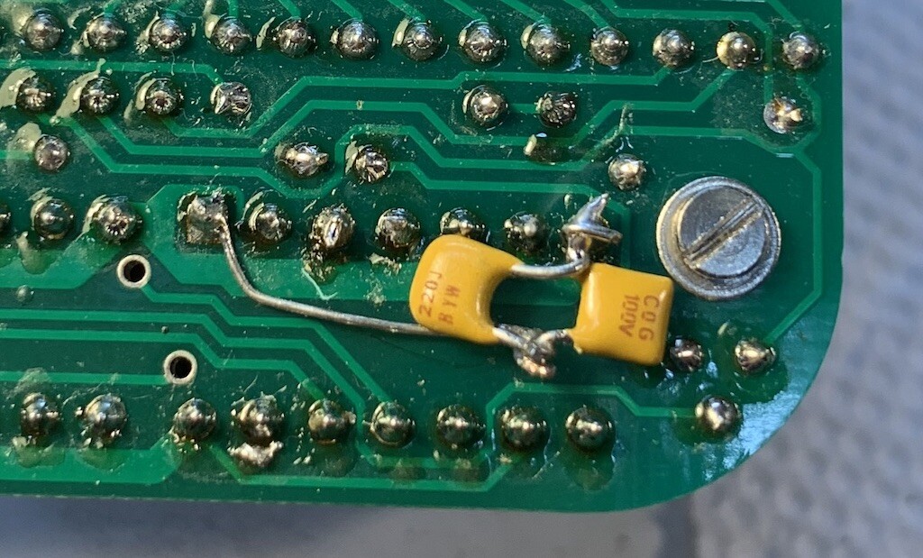
Apr 2022: segment display brightness: I think I'll change the 7seg LED series resistors to [220 ohms from 100 ohms], as right now they are brighter than the individual LEDs.
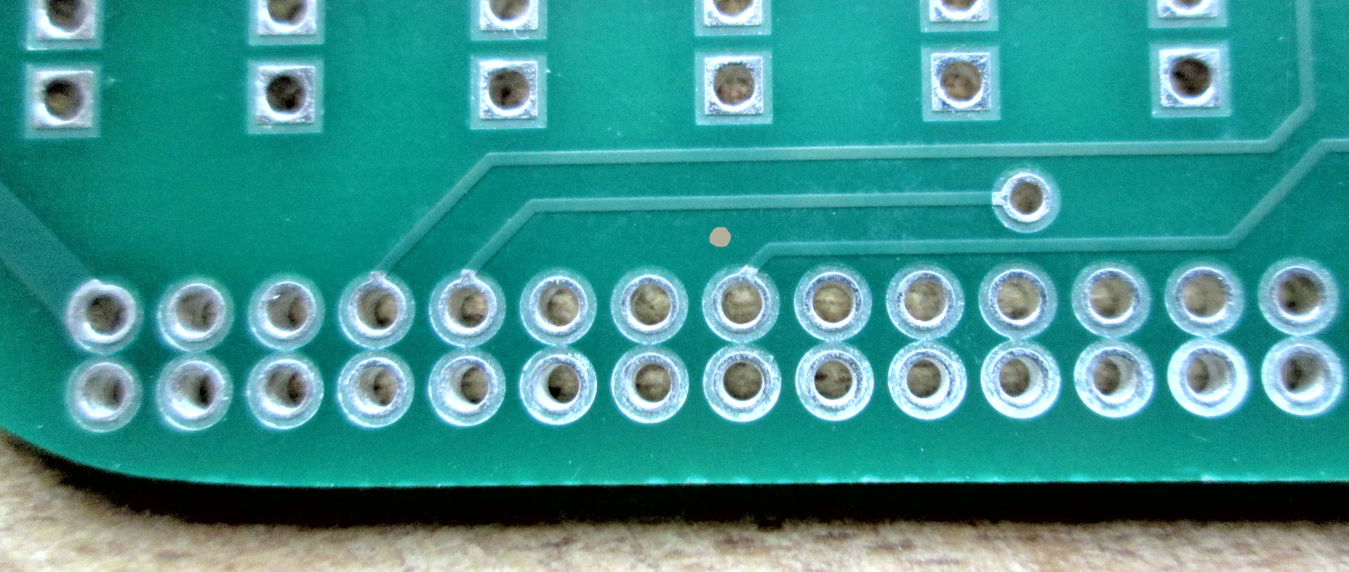
Apr 2022: Display interrupt disable Pre-production of the Rev L front-panel had the display timer wired to /INT through Q6. But without interrupt handling software, those interrupts will crash most software. Lee initially documented
not installing Q6 on those boards, to disable the timer interrupt. Later production of the FP includes a jumper P9 (near
the IN switch) to break the interrupt. From either the jumper, or from a break on the PC board trace to the interrupt pin (colored dot on image) , a wire could be added to /EF1 for test software or as an alternative to the interrupt.
Apr 2022: Access to 8-bit I/O ports, without DB-25 [Previous versions of the 1802 Front Panel had a DB-25 connector to the CPU's input and output I/O ports, 1802 signals, serial signals. But] all the signals that were on the DB25 are still on the 30-pin header.. The Front Panel [PC board] has two rows of holes. So you can install a 30-pin male header on the Front Panel to provide access to them." - Lee Hart. For details of operation of
those signals, review previous versions of the 1802 MC front-panel which reference most of the same signals
from the DB-25 on those versions. - Herb Johnson
This Web site has dozens of Web pages about hardware, software, operation and upgrades and debugging of the Membership Card. Please, please look at the Home Page of the 1802 Membership Card for links to those notes. Collections of hardware note Web links and software note Web links are on these linked pages.
Here's operation of the Rev J M/S card with BASIC 3 and an FTDI-chipped USB serial adapter. Some details and history of BASIC 3 and USB serial adapters
are below.
June 2021: Diskless Elf/OS ROM available Diskless Elf/OS ROM by Mike Riley gives you a taste of everything! It has Tiny BASIC, FORTH, Lisp, VTL2, a monitor, simulator, a mini-editor/assembler, and XMODEM
upload/download. See links to the 1802 Membership Card sales page to get the binary ROM image and find more details.
2018: Lee Hart and Chuck Yakym provide a BASIC, Tiny BASIC, and ROM monitor, as binary images you can download to burn into a PROM. See Lee's 1802 M/S card sales page, look under under "BASIC for the 1802". Choose the "Rev J" version for your rev J CPU board. Details are in the ZIP files and on his site. There may be in-development versions on the cosmacelf Yahoo Web site in the "files" section, "Basic 3" folder by Chuck "the-eagle". again, choose "Rev J". New for Rev L CPU: The Yakyam ROM monitor starts with a jump to high memory; so it may be a candidate for "jump to 8000H on reset" by the Rev L CPU. See these notes for details.
June 2017: Many people use a USB to serial adapter to operate the 1802 Membership Card serial port. Over time, it's been discovered that these adapters introduce hardware buffering of characters sent and recieved. This buffering interferes with timing delays caused by 1802 software, and delays deliberately added by "terminal" programs on the PC in use. Here's a Tech Note which is from discussion of these issues, taken from the cosmacelf Yahoo discussion group. - Herb Johnson
June 2017: Many people want to use a USB to serial adapter to operate the 1802 Membership Card serial & power port. Check the Rev I Engineering notes for some considerations about the power/serial connector.
These USB devices require "software drivers", which aren't always easy to install and use. Different USB "chips" give different results. Over time, it's been discovered that these USB-chip adapters, introduce hardware and software buffering of characters sent and recieved. This buffering interferes with timing delays caused by 1802 software, and delays deliberately added by "terminal" programs on the PC in use. Here's a Tech Note which is from discussion of these issues, taken from the cosmacelf Yahoo discussion group. - Herb Johnson
To order: Refer to the Membership Card home page for the current ordering status. Web links there take you to developer Lee Hart's Web site for ordering and contact. The 1802 Membership card has had many design changes: to improve operation, provide more user options, or to correct problems. Review previous version's support Web pages for discussions of those changes, or for guidance about use of the current version. Consider buying a new-version CPU or front-panel card versus modifying your version. There's often links to notes about such "mods" on the previous support pages.
Mar 5 2024: rev L1 CPU in distribution. A mod to adjust for speed of RAM with a capacitor and a jumper.
See this brief and linked Tech Note for details. This adjustment may apply to older
1802 MC's with slower/faster 4013 (TPB flip flop) and or RAM.
July 1 2022: rev L CPU added to Rev L front-panel for distribution. The Rev L CPU has a
jump-on-reset feature. This Web page describes the Rev L boards.
May 2022: redesign to produce and distribute Rev L Front Panel. Rev K4 CPU was still in distribution.
see the Rev K4L Web page for details. The Rev L front panel needs a software interrupt handler to handle six digits but can display two hex digits without software. This Web page describes the Rev L boards. Example interrupt code, is in this linked document..
Dec 17 2021: improvement to the Rev K4 kit include a 4.0Mhz ceramic resonator, machine-pin
low-profile sockets.
June 14 2021: Rev K4 CPU was in distribution with Rev K front panel. Several small circuit
changes made, see the K4 Web page Engineering section. see the Rev K4 Web page for details.
June 2021: Diskless Elf/OS ROM available Diskless Elf/OS ROM by Mike Riley gives you a taste of everything! It has Tiny BASIC, FORTH, Lisp, VTL2, a monitor, simulator, a mini-editor/assembler, and XMODEM
upload/download. See links to the 1802 Membership Card sales page to get the binary ROM image and find more details.
Sept 2020: Rev K3 CPU was in distribution until June 14 2021. Sold with Rev J front panel until Jan 2021; or with K front panel later. Rev K3 CPU changes U7 from 74HC374 to 74HC273. The Rev K front panel adds labels on its 30-pin connector. These are also documented on the Rev K4 Web page.
Check the 1802 M/S Card home page, for links to ALL previous version Web pages. Further details of production and change history are on a history of production Web page.
45 years ago as of 2023, Lee Hart produced an 1802 single board computer called BASYS. Look at the BASYS manual for hardware interface suggestions for the Membership Card.
Refer to the Membership Card home page for the current ordering status. A Web link takes you to developer Lee Hart's Web site for ordering and contact.
This page and edited content is copyright Herb Johnson (c) 2024.
Contact Herb at www.retrotechnology.com, an email address is available on that page..
Errors, corrections, component changes
- install an older 4013
OR
- add a 330pF capacitor between U5 (4013) pin 1 to GND to slow it down
OR
- cut the trace to U4 (74HC139) pin 13, and jumper pin 13 to pin 16
You only need to do ONE of these -- any one will fix the problem. It also won't hurt to do one of them anyway, even if it's not needed." - Lee Hart. Here's a photo of adding two smaller-value caps (in parallel) to under U5, by John S.
Hardware and software and notes about them
Recent History of 1802 Membership Card production.
How to Order