![[rev D CPU]](revD_cpu_ca.jpg)
Last updated JUne 13 2014. Edited by Herb Johnson, (c) Herb Johnson, except for content written by Lee Hart and others. Contact Herb at www.retrotechnology.com, an email address is on that page.
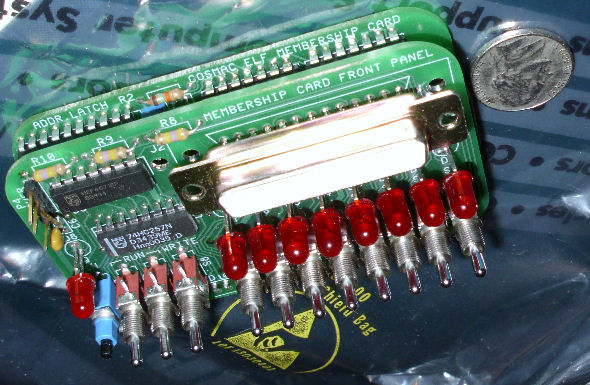
![[rev D assembled]](revD_case_ca.jpg)
This is the support page for the Rev D & E Membership Card. the Rev D and E are now out of production as of 2014.
"For those just tuning in, the Membership Card is a reproduction of the original Popular Electronics Elf computer, but shrunk to fit in an Altoids tin! It works the same, and runs the same software." - Lee Hart, developer. The Membership card home Web page has links to previous versions, history, testing, hardware notes and software - and HOW TO ORDER. This page has information specific to the Rev D and E card. (Rev E has no design changes, just minor board layout fixes.)
The photo on the left is the Rev D CPU board. (Rev E is a minor PC board change.) The photo on the right is the assembled Membership Card with front cover, in TWO Altoids tins! Photos courtesy of Cristian Arezzini Dec 2012. He says "I used two cans because I wanted something totally self-contained. The top tin contains the computer, the bottom tin contains the batteries and "sleep" switch. The small white cable brings power to the computer. This way I can take it with me without worrying about loose cables or connectors or such... :)"
![[empty boards]](mship_revcbd1.jpg)
![[parts kit]](mship_revbparts1.jpg)
![[empty boards]](mship_revcpan.jpg)
Documentation: The Rev D & E manual is a .PDF file at this link. dated Aug 29 2012.
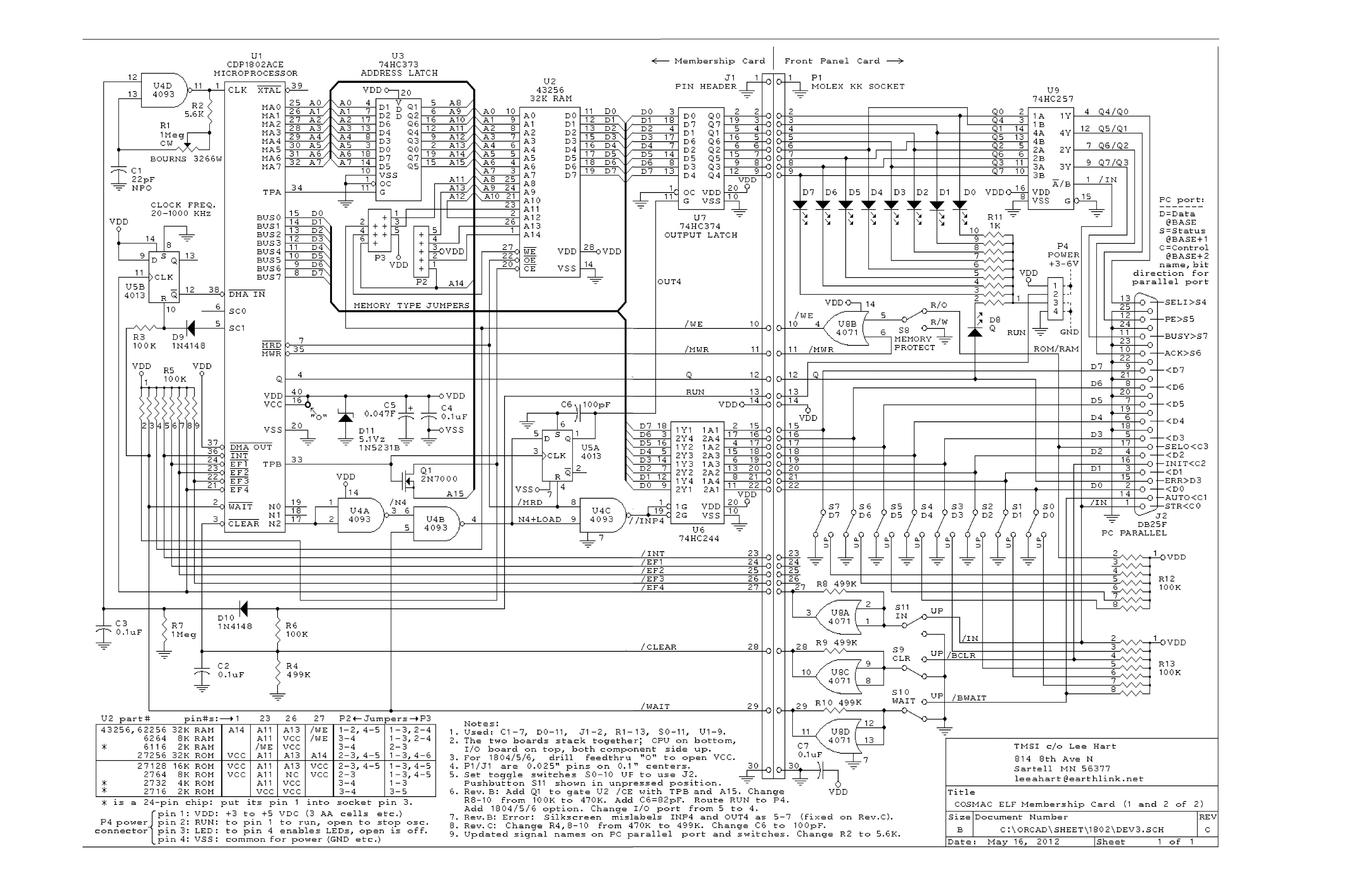
Here's the link to the Rev D schematic .PDF. dated Aug 31 2012.
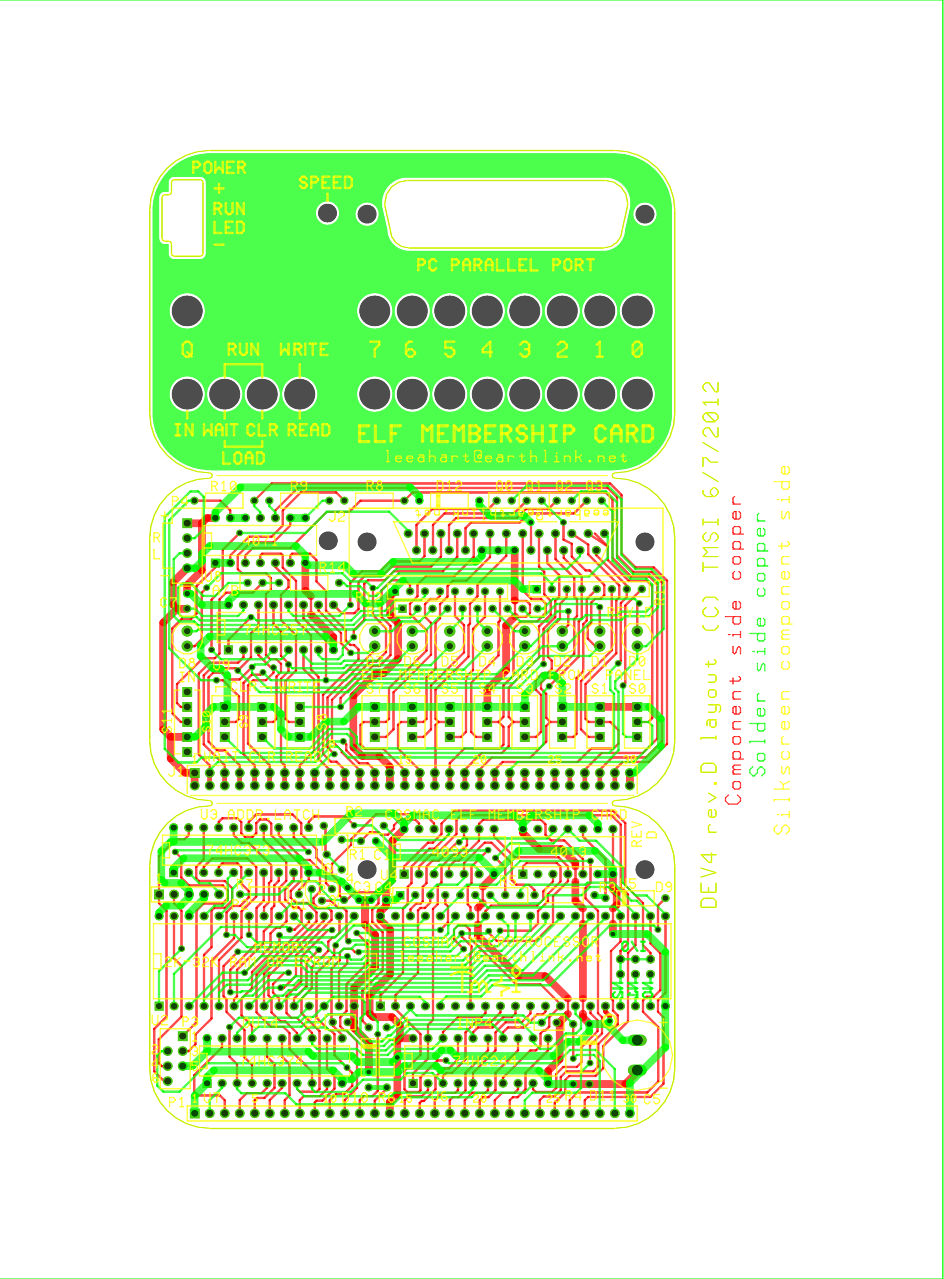
Here's the link to the Rev D boards layout .JPG . dated June 7 2012.
Here's a compact Membership Card and 1802 operating guide PDF dated Aug 12 2012.
Also, here are Rev C to D differences notes.
On the left is a Rev B kit parts from Oct 2010; the Rev D & E parts kit looks very much the same. The unpopulated Rev C logic boards from Aug 2011 are shown on the right; Rev E boards are shown below. Also on the right, is a a front panel cover card, available at additional cost. Rev D product descriptions are below.
Refer to the Membership Card home page for the ordering Web link. An email contact address is there for special orders. - Herb Johnson
Initial testing and programming
Rev D description
Engineering Data
Errors and corrections
Chronology from Rev C to Rev D
See this document on Testing the 1802 Membership Card with small toggle-in programs. Basic operations of the front panel are described. Use of the parallel port for programming will be described in this linked document. Other links to testing hardware and software are on listed on the home Web page. - Herb Johnson
The Rev D & E Membership card consists of a CPU board stacked on a Front Panel board. The Rev D & E versions are very much like previous revisions, except for a number of layout changes for more customer options. You can also buy a cover board, "a circuit board to cover the switches and lights of the Front Panel card.
![[rev E CPU]](mship_revecpubd.jpg)
- 1802 microprocessor (option for 1804/5/6 without load mode). - 2k-32k memory chip socket; accepts 6116 2k RAM 6264 8k RAM 62256 32k RAM 2716 2k EPROM 2732 4k EPROM 2764 8k EPROM 27128 16k EPROM 27256 32k EPROM (or equivalents) - supercapacitor to maintain RAM contents with power off - one 8-bit output port (OUT4 default, *new* you can jumper-select others) - output port multiplexed to four DB-25 pins (PC parallel port) - *new* OR all 8 bits to eight DB-25 pins (jumper selected) - one 8-bit input port (INP4 default *new* you can jumper-select others) - *new* jumper select on board ROM/RAM for high or low 32K address space - *new* +5 volt power input option at DB-25 pin 18 w/diode protection (jumper selected) - RC clock with pot (slow for low power, fast for high speed) - the usual 1802 I/O bits (Q, EF1-EF4, INT, etc.) - all I/O and power brought out to a 30-pin header - size: 3.5" x 2.125" - power: 3-6vdc at 1ma (plus whatever the memory chip chosen requires)
![[rev E front panel]](mship_revefrontbd.jpg)
- plugs onto the 30-pin connector of the Membership Card
- provides the Elf front panel interface and DB-25 interface
- 8 data output LEDs (memory reads and OUT4)
- 1 Q output LED
- 8 data input toggle switches (memory writes and INP4)
- read/write memory, run/clear, run/load toggle switches
- 1 input and EF4 pushbutton
- "stand alone" memory read, write, program load, and run operations
- no PC, external hardware, or any onboard program, are required.
- size: 3.5" x 2.125"
- power: adds about 3ma for each LED lit
DB-25 PC parallel port connector on Front Panel: - has all I/O and control signals to classic PC parallel port - allow full front panel operation by a PC (with appropriate software). - *new* OR expanded output and +5 supply features for non-PC use.
The Membership Card front panel cover is a PC board, with holes for the switches and lights and PC parallel
port D-connector, silkscreened labels, and a solid sheet of copper on
the back. Cut a large rough rectangular hole in the Altoids box, and
solder or epoxy this board to the top to provide a neat finished front
panel." - Lee Hart
The two boards stack, and will fit in an Altoids tin. The front panel cover board (optional) fits over the Altoids lid. Only common readily available electronic parts are used (the 1802 is the hardest part to get). All thru-hole parts, for easy assembly (no surface mount).
Standby mode, nonvolitile RAM: Seperating the CPU board from the Front Panel will put the CPU board into a "standby state", program halted and RAM powered by the supercapacitor. But removing the power connector "should" disconnect the RAM from the rest of the system. [Lee, please update this description? - Herb]
*new* dual ROM/RAM operation, four I/O ports For rev D, two CPU boards can be stacked by using a CPU socket to connect the two boards. One of them is has the CPU chips and either ROM or RAM; the other is driven by the CPU and used to hold ROM or RAM; and provide another pair of input and output ports at another address. This will be documented at a later time. This list of Rev C to D notes will provide some guidance. Also, here's a Tech Note about stacking two Rev C Membership Card CPU boards.
Refer to the Membership Card home page for the current ordering status of the Rev D kit. An email address is there to order or contact.
Here's some engineering notes about power consumption, program retention, current consumption of LED's by color. There's more information from previous versions. Here's the Rev C description, and here's the Rev B description.
Designed Nov 2012, first sold Jan 2013. Minor layout changes:
Added a 2nd pair of holes for the supercapacitor to allow using parts on 0.4" centers instead of the 0.2" centers at present. parts on 0.4" centers are easier to find.
Removed a speck from a trace on the DB25 connector. It did no harm, but removing it increases spacing in one spot.
Lee Hart reports Aug 12: "A customer reported a couple bugs in rev.D.
1. The board itself has an extra trace between DB25 connector pins 1-2. It doesn't cause a short, but it's close. A little extra solder on pin 1 and it could short.
I removed the extra trace from the layout, so it will be gone from future board orders. I will be grinding off that extra trace with a Dremel moto-tool on existing stock.
2. Note 4 on the schematic said all toggle switches should be UP to use the DB25 with a PC. Switch S8 should be DOWN. I just fixed the note on the schematic, and uploaded it to my website at http://www.sunrise-EV/MembershipCard/DEV4.pdf
3. There are a couple updates needed to the "cheat sheet" for rev.D. DB25 connector J2 pins 18 and 22-25 have changed. I haven't made the corrections yet, but will provide the new file when I do. - Lee Hart
There are very few changes from the Rev B to the Rev C. The Rev D adds features. So, much of the Rev B documentation applies to the Rev D. The assembled kit (Rev A is shown on the left) looks largely the same for all rev's. There's also a front panel cover card available, a PC board which will fit Rev B, C or D front panels. Check the Membership Card home Web page for more information, links, and the current status of the kits.
Toggle switch change from Rev B, C: The holes for the toggle switches are smaller on the Rev D card. These are to accomodate a different brand/model of toggle switch. Contact Lee Hart if details are critical.
Changes from Rev B during Rev C are informative. They are listed in the rev C manual, and on the Rev C support Web page. Here's the Rev C schematic .JPG.
The Membership Card Home page has links to all software and hardware notes, and more. Also see the Rev C support page for earlier changes. Recent changes are listed below, most recent first. - Herb
This information on previous versions and links to their support pages, is now on a history of production Web page where it will be updated.
2005-2009 development history: See the Membership Card development page for years of discussion about the present Membership Card design, and the philosophy behind it.
30 years ago, Lee developed an 1802 single board computer called BASYS. Look at the BASYS manual for hardware interface suggestions for the Membership Card.
This page and edited content is copyright Herb Johnson (c) 2014. Contact Herb at www.retrotechnology.com, an email address is available on that page..