![[assembled kit]](mema_front.jpg)
Last updated Mar 30 2016, from previous May 4 2014. Edited by Herb Johnson, (c) Herb Johnson, except for content written by Lee Hart and others. Contact Herb at www.retrotechnology.com, an email address is on that page.
This is the support page for the Rev C Membership Card. "For those just tuning in, the Membership Card is a reproduction of the original Popular Electronics Elf computer, but shrunk to fit in an Altoids tin! It works the same, and runs the same software." - Lee Hart. A Rev C Membership Card general product description is at the linked Web page.
Note: as of July 2012, Rev C is out of production. This page will remain stable for Rev C owners. This page provides notes on Rev C, and
upgrades to Rev D and Rev G like operation. Web pages on later versions may be informative. See the Membership Card home page for links to the current production Web page, and to all other version Web pages. - Herb Johnson
Documentation: The Rev C manual is a .PDF file at this link.
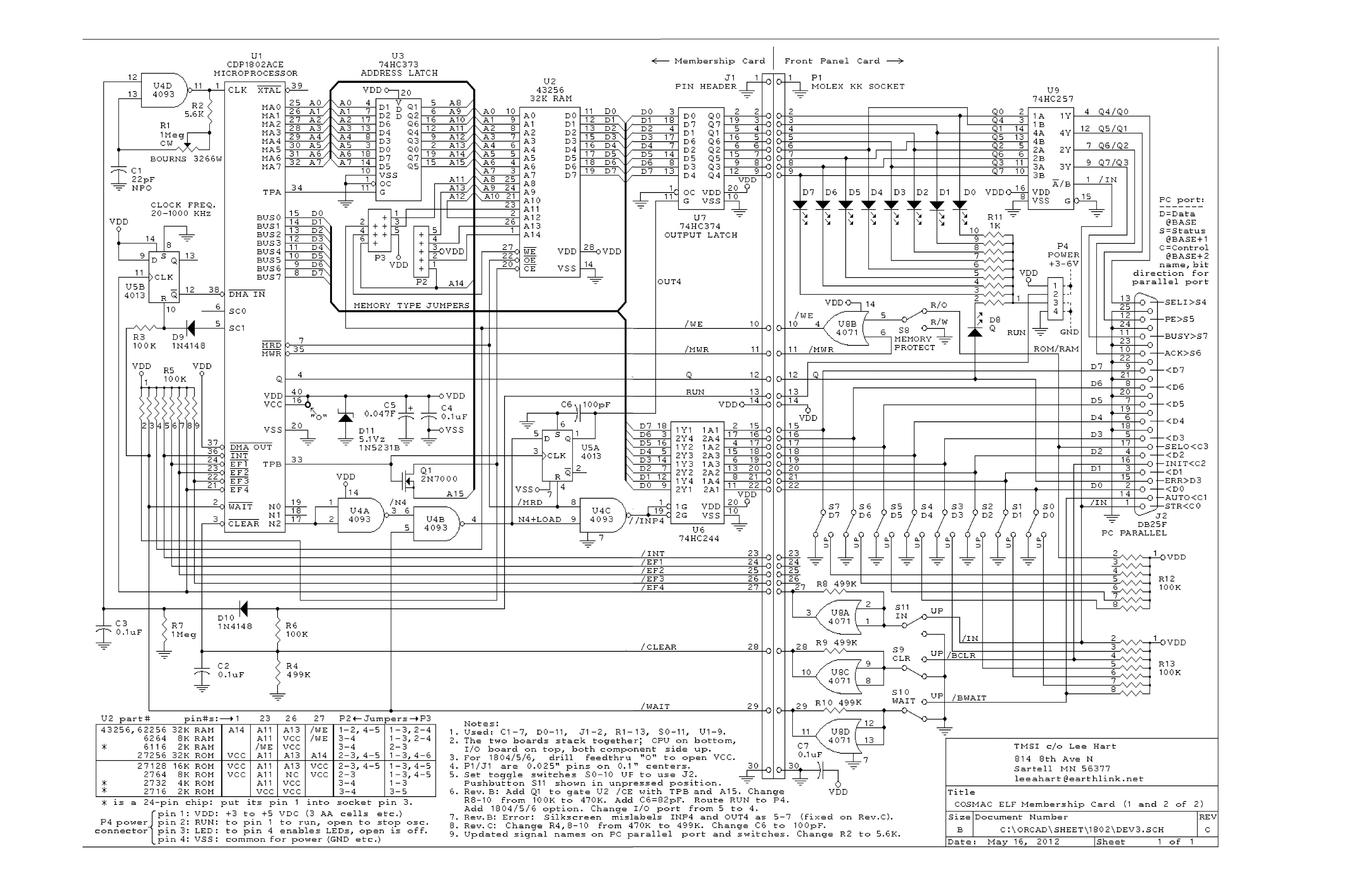
Here's the link to the Rev C schematic .JPG.
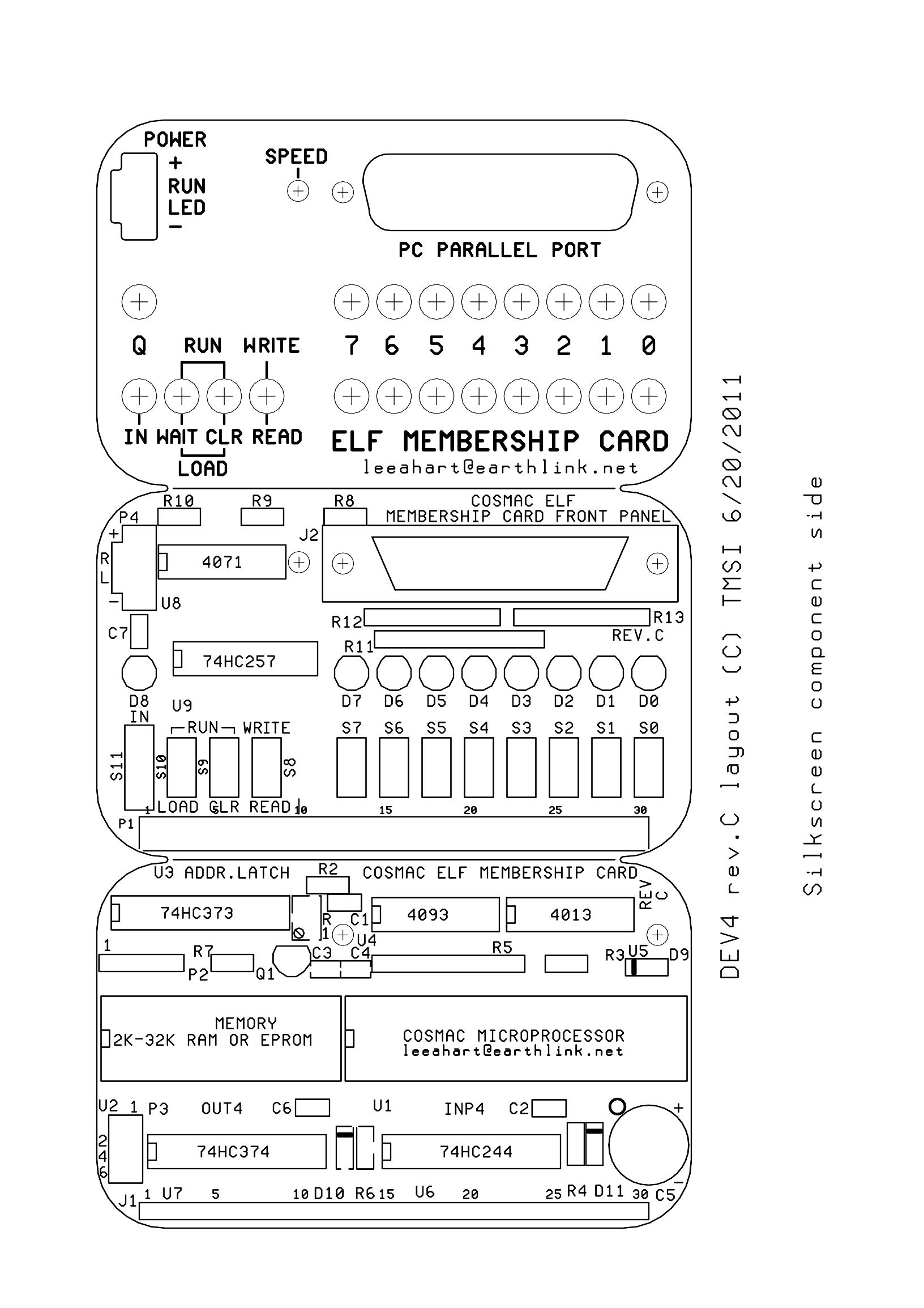
link to the Rev C boards layout .JPG .May 16 2012
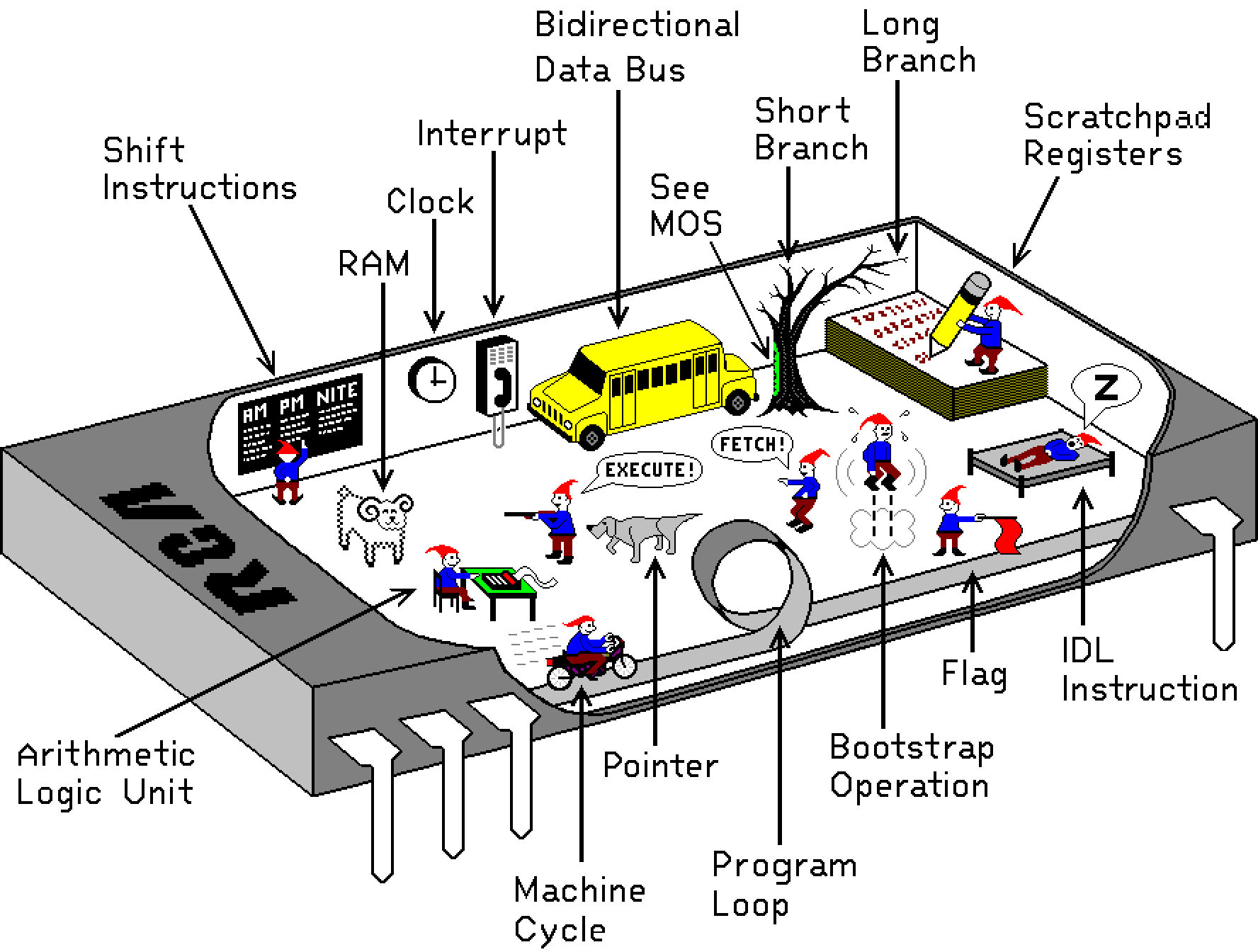
Here's a graphic of how the "elves" run the 1802May 16 2012
Here's a compact Membership Card and 1802 operating guide PDF
Testing and operating the 1802 Membership Card with small toggle-in programs.
Additional documentation and discussion, changes at the end of this Web page
![[empty boards]](mship_revcbd1.jpg)
![[parts kit]](mship_revbparts1.jpg)
![[empty boards]](mship_revcpan.jpg) On the left is a Rev B kit parts from Oct 2010; the Rev C parts kit will look the same. The unpopulated Rev C logic boards from Aug 2011 are shown on the right. Also on the right, is a a front panel cover card, available seperately for Rev B or C owners. Rev C card descriptions are below.
On the left is a Rev B kit parts from Oct 2010; the Rev C parts kit will look the same. The unpopulated Rev C logic boards from Aug 2011 are shown on the right. Also on the right, is a a front panel cover card, available seperately for Rev B or C owners. Rev C card descriptions are below.
The Membership card home Web page has links to previous and current versions, history, testing hardware and all software. - Herb Johnson
Refer to the Membership Card home page for the current ordering status of the Rev C kits. An email address is there to order or contact. - Herb Johnson
Initial testing and programming
Rev C description
Engineering Data
Errors and corrections
See this document on Testing the 1802 Membership Card with small toggle-in programs. Basic operations of the front panel are described. Use of the parallel port for programming will be described in this linked document. Other links to testing hardware and software are on the Rev A development Web page. - Herb Johnson
The Rev C version is identical to the Rev B except for a few small layout changes. There's also a a front panel cover card available, a PC board to cover the front of the Altoids box. - Herb
- 1802 microprocessor (option for 1804/5/6 without load mode).
- 2k-32k memory chip socket; accepts
6116 2k RAM 6264 8k RAM 62256 32k RAM
2716 2k EPROM 2732 4k EPROM 2764 8k EPROM
27128 16k EPROM 27256 32k EPROM (or equivalents)

- supercapacitor to maintain RAM contents with power off
- one 8-bit output port (OUT4)
- one 8-bit input port (INP4)
- RC clock with pot (slow for low power, fast for high speed)
- the usual 1802 I/O bits (Q, EF1-EF4, INT, etc.)
- all I/O and power brought out to a 30-pin header
- size: 3.5" x 2.125"
- power: 3-6vdc at 1ma (plus whatever the memory chip chosen requires)
- plugs onto the 30-pin connector of the Membership Card
- provides the Elf front panel interface and DB-25 interface
- 8 data output LEDs (memory reads and OUT4)
- 1 Q output LED
- 8 data input toggle switches (memory writes and INP4)
- read/write memory, run/clear, run/load toggle switches
- 1 input and EF4 pushbutton
- "stand alone" memory read, write, program load, and run operations
- no PC, external hardware, or any onboard program, are required.
- size: 3.5" x 2.125"
- power: adds about 3ma for each LED lit
DB-25 PC parallel port connector on Front Panel:
- has all I/O and control signals to classic PC parallel port
- allow full front panel operation by a PC
(with appropriate software).
Here's a link to the Rev c schematic of the logic cards.
July 13 2011, Lee Hart: "I just finished making some Membership Card front panel [covers]. It
is a PC board, with holes for the switches and lights and PC parallel
port D-connector, silkscreened labels, and a solid sheet of copper on
the back. Cut a large rough rectangular hole in the Altoids box, and
solder or epoxy this board to the top to provide a neat finished front
panel." - Lee Hart
The two boards stack, and will fit in an Altoids tin. The front panel cover board (optional) fits over the Altoids lid. Only common readily available electronic parts are used (the 1802 is the hardest part to get). All thru-hole parts, for easy assembly (no surface mount).
Refer to the Membership Card home page for the current ordering status of the Rev C kit. An email address is there to order or contact.
Sept 5 2010: Rev B Power consumption
I built my own and have done some testing. Power consumption is definitely reduced. Power consumption running a program with the pot at min/max frequencies, with a Hitachi HM62256P-12 32k byte RAM:
VCC    ICC at clock(min)    ICC at clock(max)
---    ----------------    ----------------
3v    .12ma    13.5 KHz    .39ma    280 KHz
4v    .25ma    9.24 KHz    .71ma    350 KHz
5v    .45ma    7.45 KHz    1.06ma    341 KHz
I've had it save a program for 10 minutes [powered only by the supercapacitor].
Sept 30 2010, lee hart Responding to a question, Lee said "With the rev.B board, a Hitachi HM62256 32k RAM is drawing well under under half a milliamp *running*. AA alkaline cells are good for that for about a year. The front panel draws essentially zero, if the LEDs are off and the data switches are up. Plus, I've done a little more testing, with different RAM chips and on two different boards. The above numbers are fairly representative. I'll try to tabulate the differences between RAM chips, as that is the largest variable." - Lee Hart
Zener diode D11
The part supplied is a 1N5231B 5.1v 5% 500mw zener diode. It's fine for general use, and does a good job of holding the max supply voltage under 5.5v to protect the supercap C5.
But it draws more supply current. I also got some low-power 1N4625 5.1v 250mw zeners. They draw about 1/10th the current at any given voltage. This is good for micropower applications, but a higher voltage supply can easily overwhelm its ability to keep C5 under 5.5v. Here are the supply currents of these two zeners (average of 5 parts of each):
VCC =     3v        4v     5v     5.5v    6v
-----     --        --     --     ----    --
1N5231    1.4ua    26ua    6ma    44ma    86ma
1N4625    0.35ua    8ua    .12ua  1.8ma   30ma
LEDs
I've tried several different colors of LEDs. Whites cost the most, and need the most voltage to work; but are the brightest for a given current. Reds are the opposite; cheaper, lower brightness, lowest operating voltage. I'm supplying red LEDs and R11=1k with the kits. Here is the additional supply current per LED, and perceived brightnesses at different VCC voltages for the two extremes:
         R11    2v    3v    4v    5v
         ---    --    --    --    --
white   3.3k    0ma    .12ma    .38ma    .68ma
                off    dim    normal    bright
          1k    0ma    .27ma    1.1ma    2.05ma
                off    normal    bright    very bright
red     3.3k    .13ma    .43ma    .73ma    1.04ma
                very dim    dim    dim    normal
          1k    .39ma    1.35ma    2.33ma    3.31ma
                dim    normal    bright    very bright
- Lee Hart
standby mode, nonvolitile RAM: You don't have to remove the Front Panel board to go into standby (minimal power consumption). Power connector P4 has 4 pins:
pin 1 = positive supply (3-6v)
pin 2 = Standby/Run; tie to pin 1 to run, leave it open for standby
pin 3 = LEDs; tie to pin 4 to enable LEDs, leave it open to disable
pin 4 = negative supply (3-6v)
So, for minimum standby power, open the connections between 1-2 and 3-4 with a switch. Or, note that 1v is enough to maintain memory contents, but stops the clock and other logic from drawing power.
Q: ....consider trying a NVRAM from Simtek (now Cypress Semiconductor) STK12C68 Series 64K-bit (8K-bit x 8) 5 V 300 mil DIP-28 AutoStore NVSRAM 45 ns. Or, a Dallas Semiconductor DS1225 [with mechanical mods].
A: The Membership Card has a 600-mil wide memory socket, but an adapter could be made for a 300-mil chip.... The DS1225 has a coin cell stuck on top of it, which adds to the height, and there is none to spare.
Off list, Herb Johnson suggested a little adapter board that accepts two modern surface mount chips, one RAM and one flash ROM. This would give you non-volatile storage with cheap modern chips. I didn't do this as I was deliberately restricting myself to "old school" chips and construction techniques.
One other point: Consider that an ordinary alkaline AA cell will deliver 250uA for over a year. That's enough to *run* the Membership Card! Are you sure you need nonvolatility longer than that? - Lee Hart, Oct 11 2010 on cosmacelf
data available: Q: Is there a way to signal external hardware when data is available at the output port? Worst case, I can greenwire TPB to a pin on the 30-pin connector.
A: The Q line can be used. Or use one of the 8 bits as a strobe, i.e. a 7-bit ASCII character with the high bit low, then write the same character with the high bit high. [TPB] could be done, [or] use INT or EF1-EF3, for example. - Lee Hart, Oct 23 2010 on cosmacelf
Changes from previous Revisions: There are several changes from the Rev B, including a transistor to improve OUT timing, and parts and layout changes. Check the Rev C manual for details. The assembled kit (Rev A is shown) looks much the same as the Rev A or B. There's also a front panel cover card available, a PC board which will fit Rev B or C front panels. Check the Membership Card home Web page for more information, links, and the current version and sales status of kits.
May 2014: See how to build a Rev C CPU board to work like a Rev G CPU.
July 2012: Rev D now in production. Here's a Tech Note on "rev C to D" changes and possible user upgrades of Rev C cards. Most of the changes are to provide additional features, so it's the Rev C owner's option to implement them on their Rev C card if those features are desired.
Mar 2012: If you look in the picture in my latest manual, you'll see that my Membership Card has clear (instead of red) LEDs. Those are blue LEDs. I also changed the 1k series resistor network to 3.3k, as they are *way* too bright at 1k. :-) [Note from Herb - blue LEDs consume less power, about 1ma current.]
Jan 6 2012: Here's a link to a Tech Note about stacking two Membership Card CPU boards, to double-up the RAM or ROM and also double the I/O. If anyone builds this, please contact Herb Johnson and offer comments and photos.
On Jan 2010, Lee Hart released the Rev A Membership Card. Rev B was available Dec 2010, Rev C in July 2011. Check the Rev B sheets for suggestions and improvements that may apply to Rev C. See the Membership Card development page for years of discussion about the present Membership Card design, and the philosophy behind it.
Some 2011 notes and comments about Membership card upgrades.
30 years ago, Lee developed an 1802 single board computer called BASYS. Look at the BASYS manual for hardware interface suggestions for the Membership Card.
This page and edited content is copyright Herb Johnson (c) 2016.
Contact Herb at www.retrotechnology.com, an email address is available on that page..