![[Zenith Z100 system]](z100_frontpanel.jpg)
![[Z-100 top off]](z100_notop.jpg)
Last update Feb 10 2022 (c) Herb Johnson
In August 2009 I pulled a few Heath/Zenith Z-110 systems from storage, to test and repair. I checked them a few years later and in years following. Here's some of the repairs I performed, and some of the features of the systems I have. - Herb Johnson
To go to my computer repair and restoration pages follow this link.
To go to my Heath-Zenith Web page follow this link.
Here's a link to a Z-100 power supply repair page.
To go to my S-100 Home page follow this link.
One person who helped me with Z-100 power supplies was Barry Watzman. Former Heath/Zenith Microcomputer Product Manager of the 1980's Barry Watzman died in June 2010. See this Web page for a tribute.
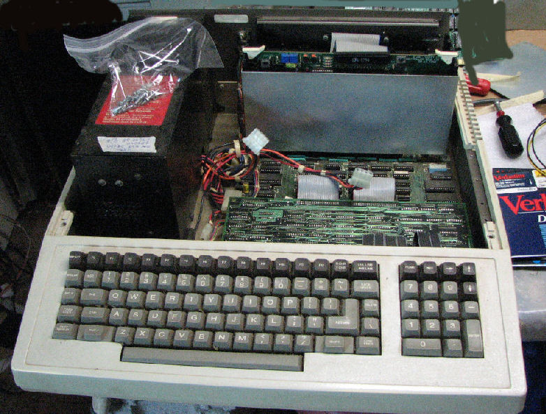
These Z-100 series systems are referred to as "low profile", because the Z-120 (B/W video & CRT) and Z-130 (color video & CRT) are the same system with an encased CRT (video tube) mounted above the motherboard, replacing the top of the Z-100 (B/W video) or Z-110 (color video).
Here's a Z-110 with front bezel detatched but still in front. This bezel fits two full-height floppy drives. Other bezels support one floppy drive on the right, full o rhalf-height, and one hard drive on the left.
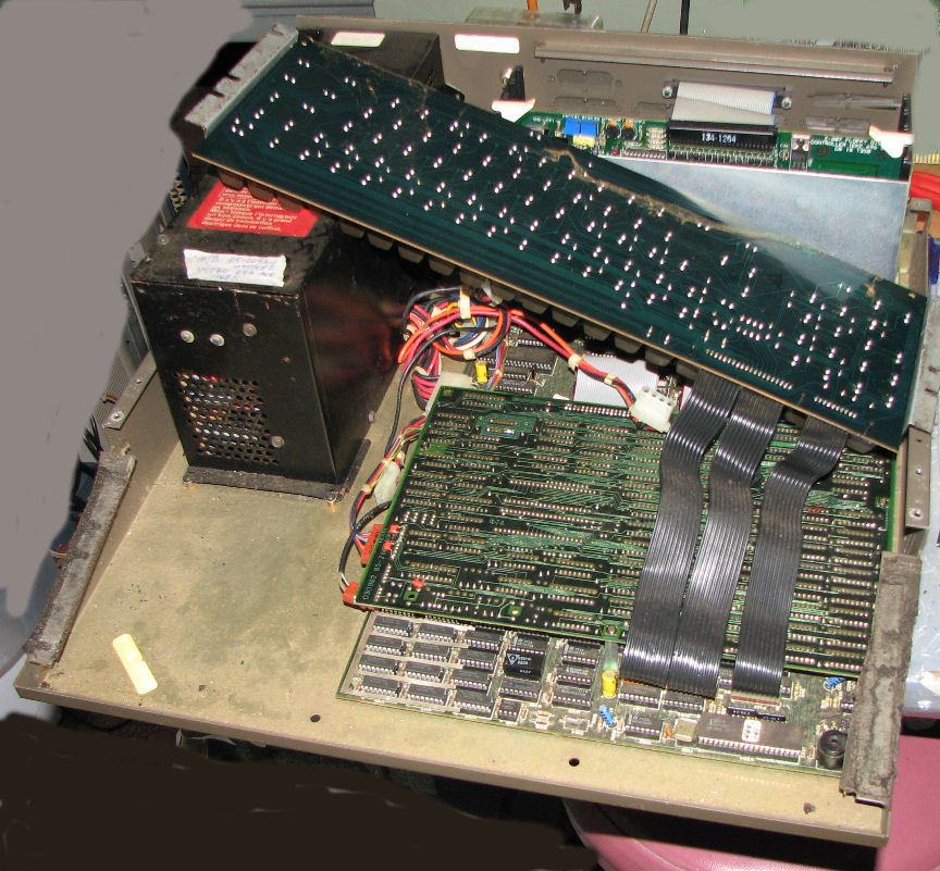
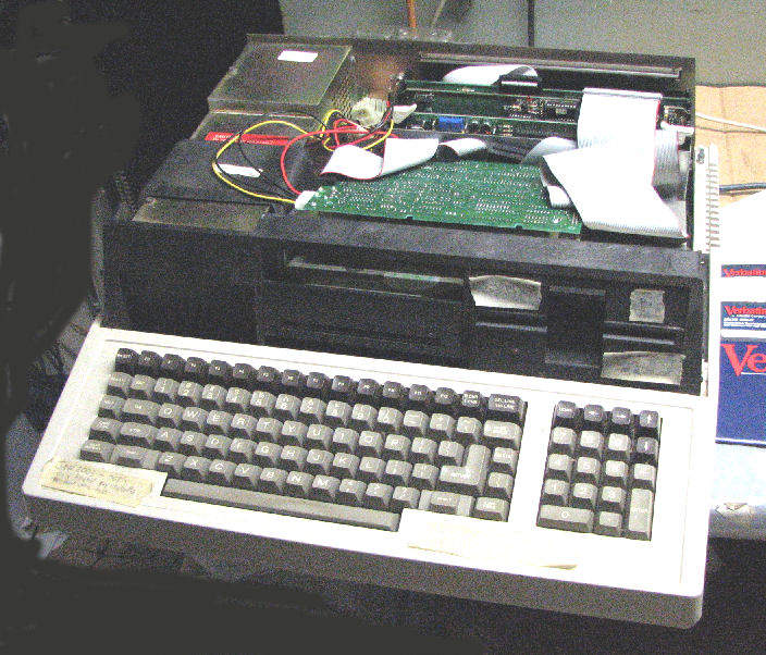
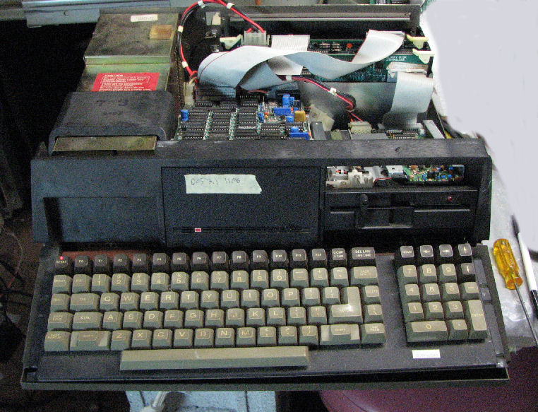
Here's another Z-110 with the top removed, exposing two half-height floppy drives
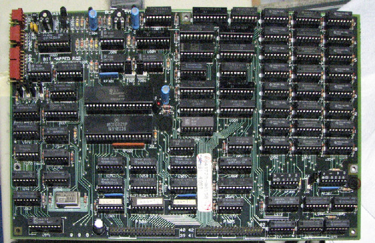
in a black fiberglass sub-frame. Note on the far left of that frame, the date "Jun 12 1983". The switching power supply in metal is to the left under the frame. Behind the drives is the 5-slot S-100 card cage, with a Zenith floppy controller card in the cage. With the drive assembly removed, you can see part of the video card as mounted on the motherboard underneath it. The Z-110 with lower case removed and keyboard lifted out of the way, the motherboard and the entire video board is exposed. Note the bottom of the keyboard; it's simply an array of key closures which is scanned by the motherboard and is cabled to it. Here's the entire motherboard.
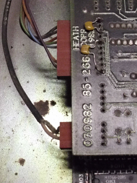
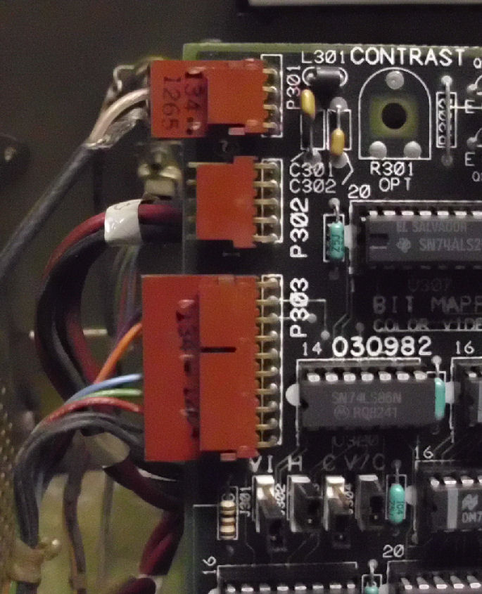
Some more views of the video card and cables. Here's a "top" view as mounted(not the component side), near the video card connectors. There's a coaxial cable near the corner, that's the composite video going out to the rear "RCA" video connector. The other connector of many wires, is the DB-9 with RGB color video. here's the same connectors on the "bottom" (component side) of the video card. The unused center connector is for a light pen!
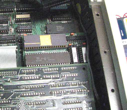
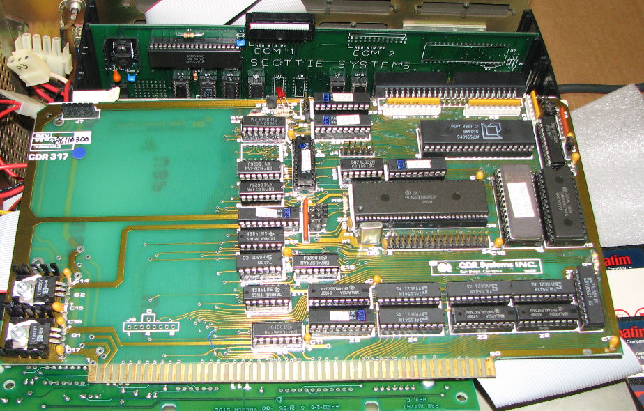
Other features of the Z-100's I examined include this 8087 daughterboard which fits in the 8088 socket. A hard-drive based Z-110 used this CDR317 SCSI controller S-100 card in addition to a SCSI/MFM adapter card mounted above the hard drive.
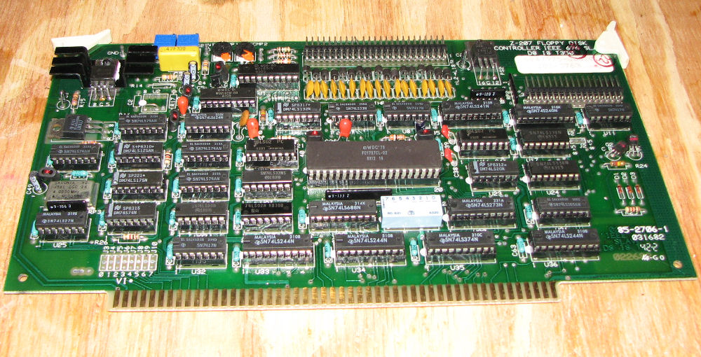
All Z-100's include the Heath floppy controller card. NOte the card has both 44 pin and 50 pin connectors, for 5.25-inch and 8-inch floppy drives respectively.
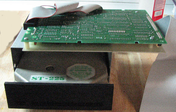
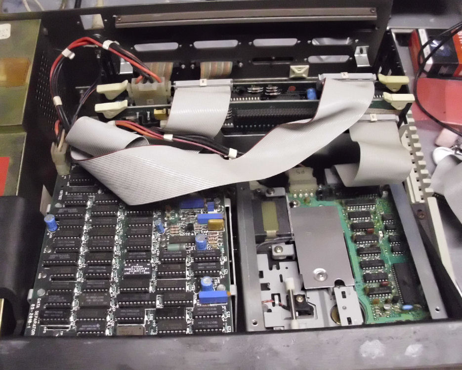
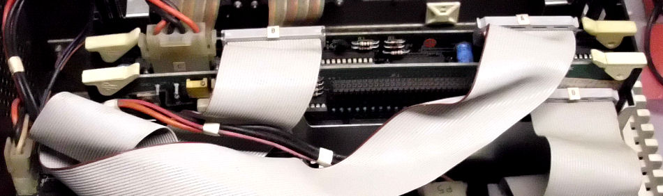
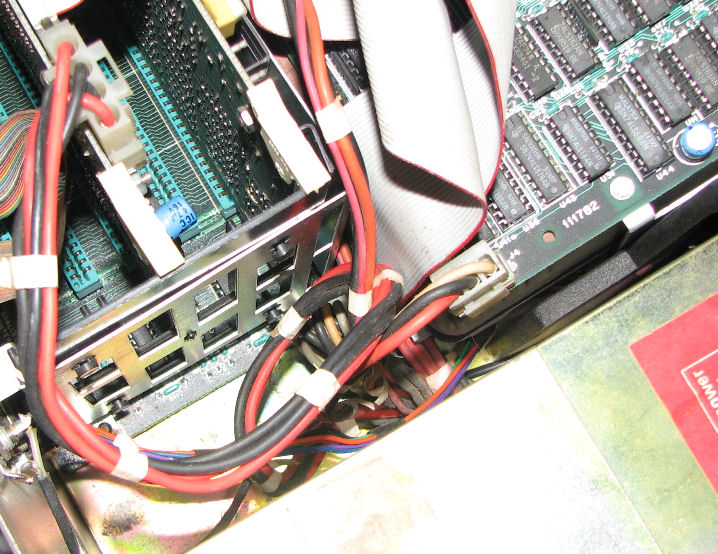
here's a view of the Zenith Z-100 hard drive as installed.The data card is on the lower left, a flopy drive on the lower right. The rear-most S-100 card is the Zenith controller, note the DC power cable to that card. The cables labled A and B connect to the MFM drive and to the controller card. The drive's data cable goes to the data card, which supports two drives. Here's a closer view of the cabling.
Other Zenith cards, and cards from other manufacturers, are shown in later sections.
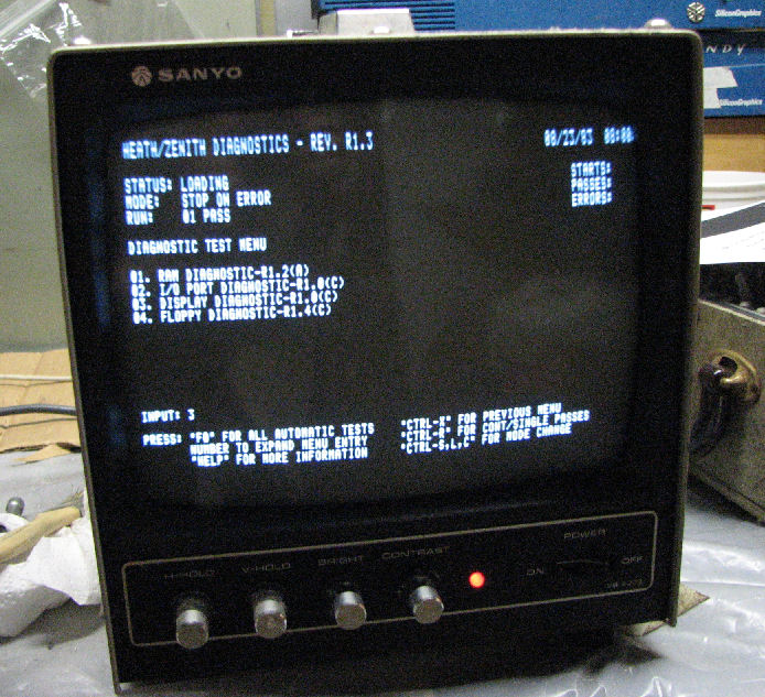
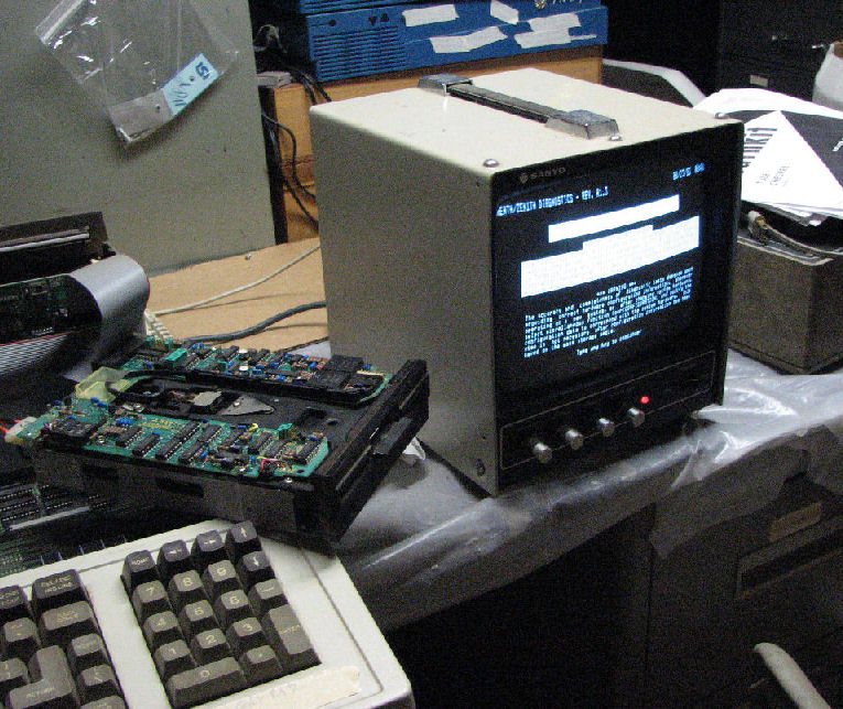
A useful part of the Zenith Z-100 system is the diagnostic software on diskette. From this photo of the Heath diagnostic screen you can see diagnostics for RAM memory, video display, I/O devices, and floppy. There is also a diagnostic for the Zenith "Winchester" hard drive controller.
In Dec 2018, I obtained a Z-100 which worked fine; except CP/M-85 didn't work "right" (DIR listings were odd-looking) and some programs would force a CP/M soft boot (return to prompt). After futzting around, I came across Steven W. Vagts' site who USED TO HAVE a Z-100 service bulletin index. and found this reference: "FSB-Z100-047: CP/M Won't Boot Properly. The 12H6 PAL IC (HE 444-128) at U186 on the motherboard has frequently caused the CP/M booting problems. On the motherboard (HE 85-2653-1), check Y101 (10 MHz crystal, HE 404-645), for proper frequency and output. Also, check U210 (8085 CPU, HE 443-1010) for poor socket contact or defective IC.". Replacing both the 8085 and the PAL solved the problem.
The index linked above, also "appeared as an insert to issue #42, November-December 1995, of the "Z-100 LifeLine".
The H/Z-100 Computers, Service Data Manual is apparently an internal Heath/Zenith repair service document. Chapter 3 of the manual describes the 8085 and PAL's operation. U186, 444-128, is a masked version of the 12H6 PAL. It controls "swap timing".
In Feb-Mar 2019, someone asked me for a replacement for the Heath Z-100's programmed Intel 8041 microcontroller (U204, 444-109) which decodes the Z-100 keyboard. They noted the source-code for the controller (it has a 1K ROM internally) is not in the Zenith documentation. Long story short, I pulled the 8041 and dumped the internal ROM (with a PROM programmer) and then disassembled the 1K program (with an available 8048 disassembler. Here's the content of the 8041 and a rough disasembly. I'll update this if my customer provides a better disassembly and/or tries an 8741 (EPROM version). - Herb
One problem with old computers, is that the soft rubber padding turns to mud or dust.In this photo I'm testing Z-110 with floppy resting casually on the system. Most of these floppy drives dated from the early 1980's with these systems. In this floppy drive photo, note the former foam padding on the front edge (to the left) as a gummy, lumpy residue. Alcohol wiped away most of the substance. It was originally applied with double-sided tape; often I could peel away the tape itself.
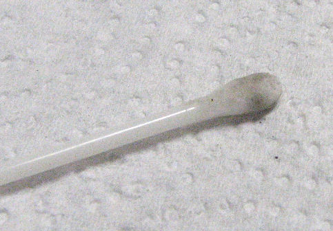
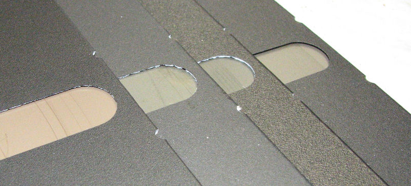
A common problem with floppy drives is a consequence of old diskette media becoming brittle and scraping away. The iron oxide coating actually strips away, as its binders become brittle. Other media problems include mold, growing on the plastic surface. Crud on the floppy head requires cleaning with Q-tip in alcohol. you can see in this photo, a Q-tip with oxide from a floppy head. When the head accumulates even a little iron oxide, it acts as a scraper, and picks up more material. A dirty or damaged read/write head, produces these scratches on media. A sharp ear can hear the difference in sound, when the drive head starts to drag or even scrape the diskette. It can cause damage not just to the "bad" diskette with fragile coatings, but to subsequent diskettes read on that drive.
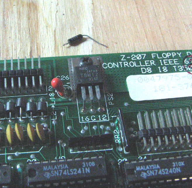
Shorted capacitors will actually ignite. One of my Z-110 systems refused to power up more than a fraction of a second. Experience told me, a tantalum power capacitor may be shorting out some DC power voltage. Fortunately the Z-100 series switching supplies simply shut down instead of failing or blowing a fuse. I pulled al the S-100 cards, and the system came up. When I put the floppy controller card it, the system failed again. I used an ohmmeter to check the DC lines, and found one shorted line. Disconnecting and measuring the capacitor on that line as shorted, identified the component failure. In this photo, a red cap is in place near the 78M12 regulator; the shorted small cap is loose above.
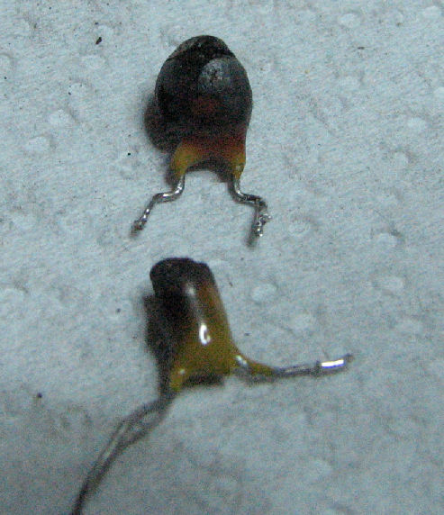
On another floppy controller, the capacitor drew so much current, it ignited. In fact, bright red smoke curled above the board, as the short did not open but continued to draw current. Identifying the failed component was no challenge, it was blackened. I cleaned the board around the component, replaced it with a similar capacitor, and the board functioned correctly. Here's some photos of burned tantalum capacitors.
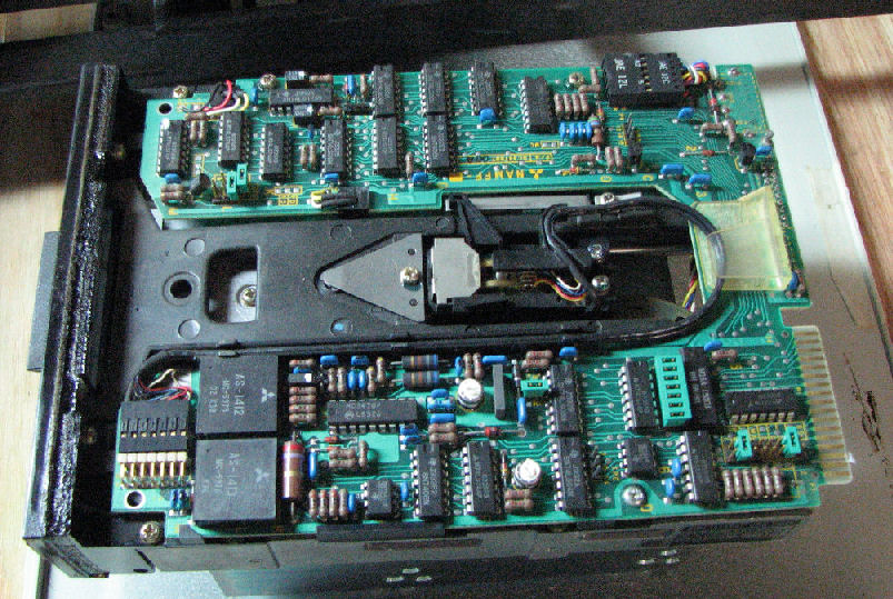
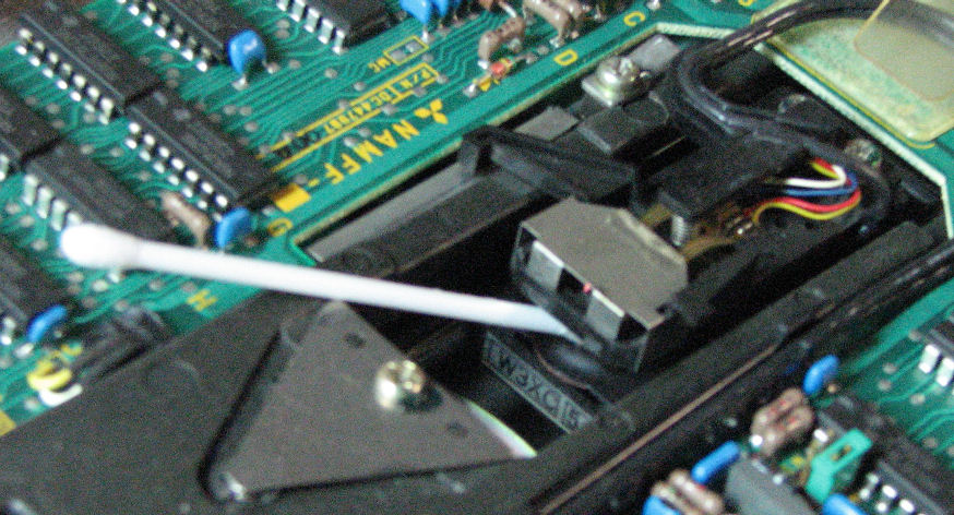
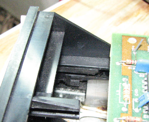
Floppy drive problems are often mechanical. I had a full-height floppy drive on one system, which would not accept a diskette. Turned out, the floppy drive's write protect sensor, was sticky. In the center of the photo, it's a small black triangle at the end of a slot. This triangle is part of a lever assembly which controls a microswitch underneath it. Unsticking the lever, allowed the disk to ride over the triangle instead of being stopped by it.
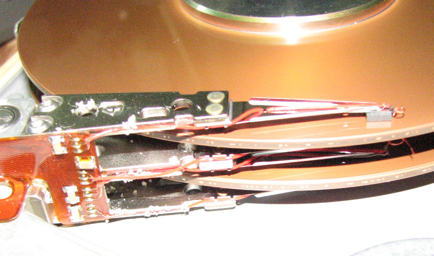
Hard drives eventually fail, and they fail hard. Here's a Z-110 with a MFM drive, a SCSI/MFM adapter card, and in the S-100 cage the CDR SCSI card. Here's a closeup photo of the SCSI/MFM adapter card mounted above the MFM hard drive. The drive did not spin up with power. So, I pulled the drive out of the system, and gave it a few manual jerks of my hand to make the interior platters spin briefly to "break" the "stiction" that is often said to be the cause of spin problems. Unfortunately, this broke the drive. If you look at the hard drive interior photo, note the sand-like crud, AND a missing head on lower arm. Where was the head? If you look at this fuzzy photo, the loose head is stuck to platter. ahead of the drive arm. OTher spots on the platters suggest the other heads were "stuck" to the platters.
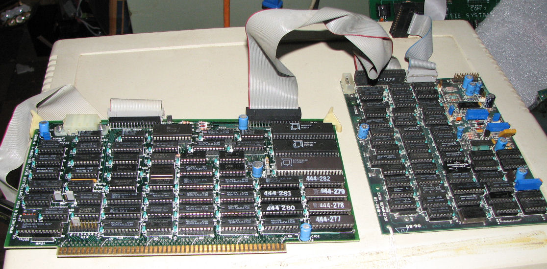
Some hard drives continue to work, even after decades.Z-110 with the Zenith hard drive controller and data seperator, on a 11MB MFM drive.
Zenith S-100 hard drive controller (left), and data seperator card (right).
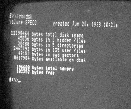
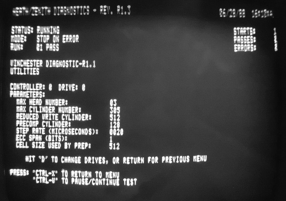
Here's a screen shot of a MS-DOS "dir" command on the MEM drive. The Z-100 series diagostics also cover the Zenith hard drive controller. Here's a screen shot of diagnostics showing some hard drive parameters.
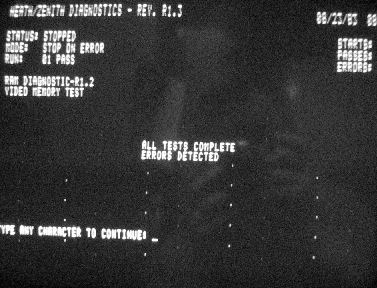
Video displays are based on RAM, and RAM will fail. the screen shows dots where video RAM is damaged.
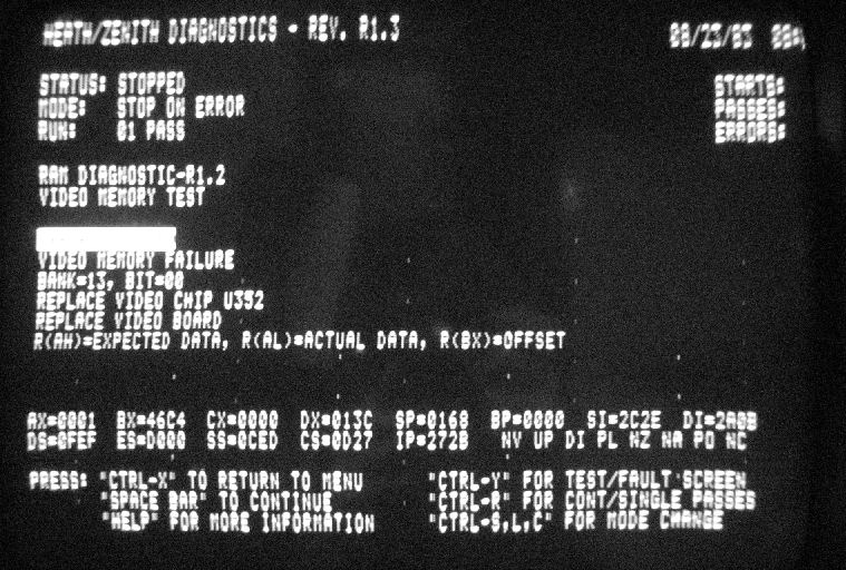
diagnostics show one of the bad VRAM locations.
Zenith Z-100 video card, with RAM on the right. the diagnostics showed two bad RAM chips by exact location. Replacing these 4164's (64K by 1) removed the "dots" from the screen.
Power supplies also fail, often with fireworks. In the course of working on the system with the "good MFM drive", I was trying to cram the drive assembly back into the system. But there was not enough space for all these DC power wires behind the hard drive. As I tried to place the drive and the wires, apparently I causes something to short out, even with the AC power switch off! The power supply started to smell and smoke, in a fashion that suggested a large capacitor was burning. Long story short, I pulled the AC cord out, and replaced the AC supply completely. There was no obvious damage to the motherboard, after one false start it came up OK with the replacement supply.
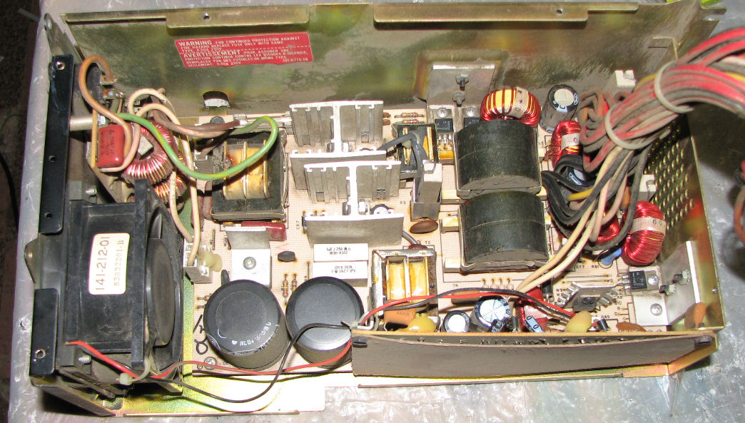
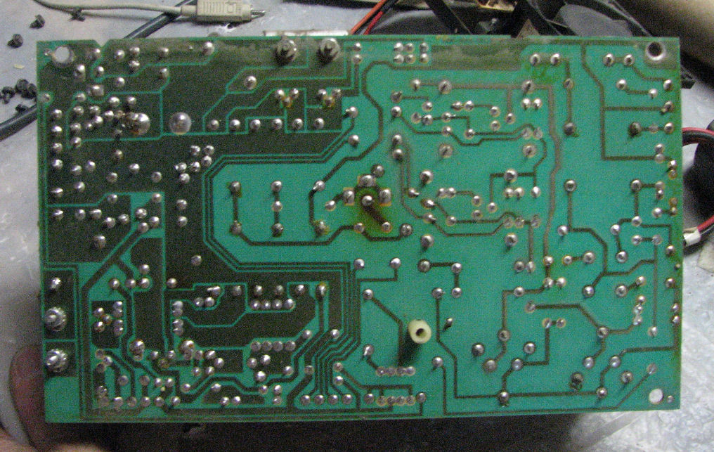
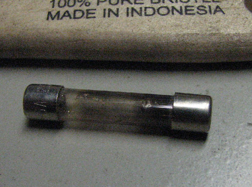
Power supplies can be repaired sometimes. When another AC supply failed with a flash of light inside, I decided to open it up on the hunch it was just a brief short that blew the fuse. Here's the interior of the Heath/Zenith switching power supply. and Here's the back of the PC board. At the time I did not have much documentation on it or schematics (but see below). I replaced the 6A fuse and tested the supply using a hard drive as a "load". Never operate a switching power supply without a load, you can cook it. But it blew the fuse immediately, here's a well-blown fuse. Checking from the AC side where the fuse is, I saw low resistance across the AC power jack, maybe 12 ohms - far too low and different from measurements on a good supply. Walking through the circuit, I saw that the full-wave rectifier was shorted on two of the four diodes.
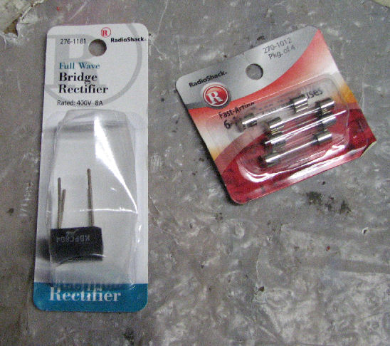
So, I needed a 6A and at least 200V or much better rectifier of the right physical size; and some 6A fuses. Wonder of wonders, Radio Shack had just the right parts!. Replacing the rectifier, and of course the fuse, did the trick!
Later in 2010, I obtained a schematic and the power supply repair notes from the Service Manual. I passed those on to Rich Lentz when he asked for help with his power supply repairs. Here's Rich's Z-100 power supply discussion. Read that page for his notes and further details. I also got some technical support from Barry Watzman, a former Zenith manager, designer and tech.
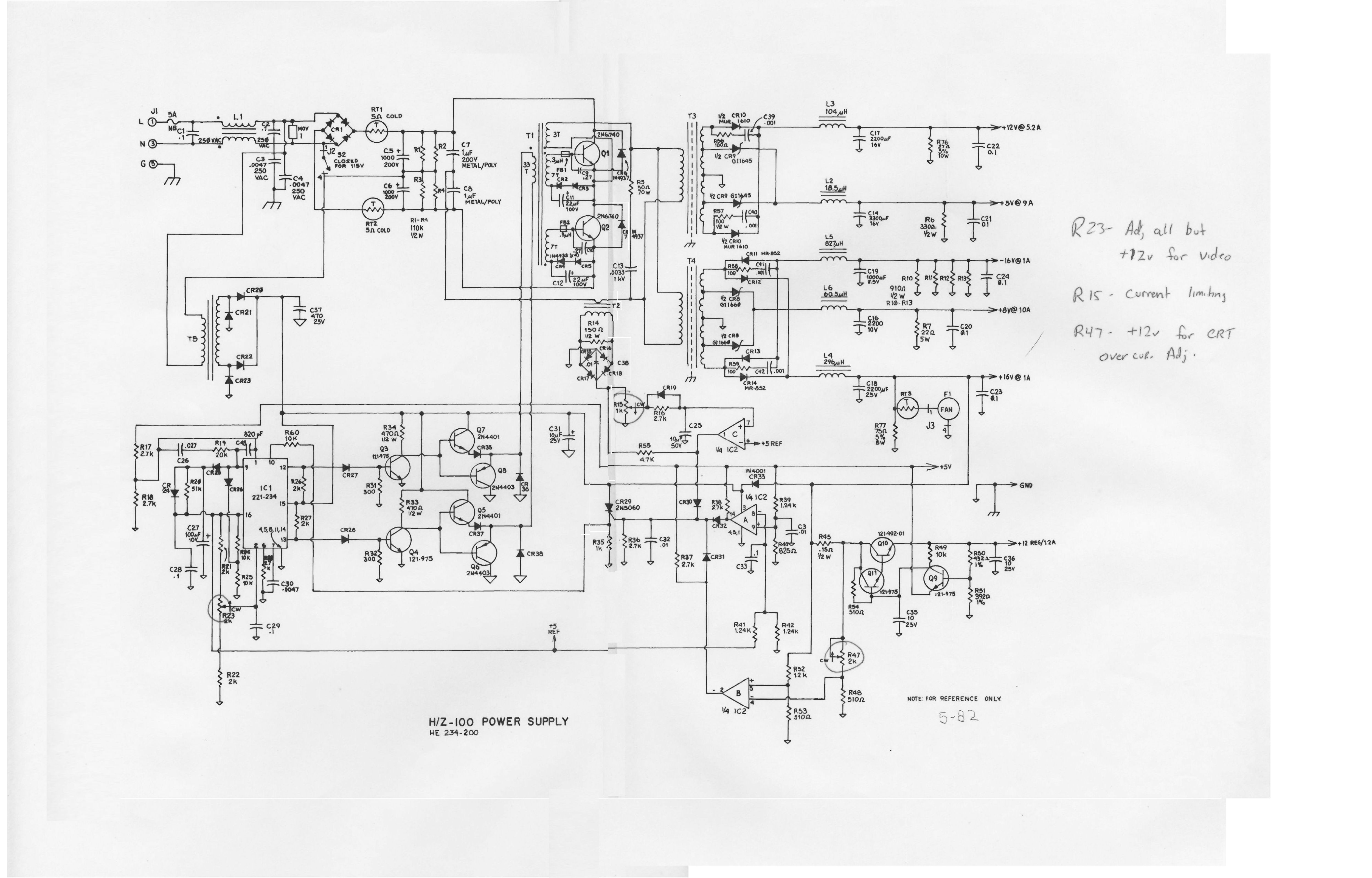
Here's the Z-100 Service Manual section on the power supply. A Web search will find a full Z-100 Service Manual on the Web. Also, here's the power supply schematic.
Unplug the Z-100 when not in use. Literally - pull the AC cord! Here's why.
In Jan 2019, I was asked about repairing a Z-100 power supply. When I re-read these notes, I see I did not mention problems with AC or RIFA caps on the hot side of the "AC power" switch. Here's a view of an opened Z-100 power supply.
Inside the Z-100 power supply, on the panel with the fan and AC switch and AC outlet, there's a small circuit board assembly. That assembly has two toroidal (doughnut) coils and you can see yellow rectangular capacitors. (One more is behind one of the coils.) Those are called "RIFA" caps. In some Z-100 models, some of these may be large disk AC (nonpolarized) capacitors. I'm told those AC caps can fail because they are "hot" even with the Z-100 power switch off. If those RIFA caps are cracked or damaged, replace them, probably replace them *all*.
Regretably, the Z-100 power supply schematic, doesn't show the AC switch and suppressor assembly. The schematic shows a "J1" connector where there's a fuse and RIFA cap (C1 .1uF) and L1 and other components. The PC board connects to J1 and also J2, on the primary power supply circuit board. Since those AC board components are "hot" even with the AC switch off, I advise you to physically disconnect the AC line cord when the Z-100 is not in use. Sigh.
I tested a number of these systems two years later in 2011. The only problems were 1)I had to reset a hard drive or floppy controller S-100 card and 2) one of my two MFM hard drives did not come up - controller or drive???? Also 3) a floppy drive went "dead". It's surprising how often a problem can be solved by cleaning contacts on boards.
Herb Johnson This page and edited content is copyright Herb Johnson (c) 2022.
Contact Herb at www.retrotechnology.com, an email address is available on that page..
New Jersey, USA