Kip Yeakel, Herb Johnson, June 2012. Last updated May 28 2015 (c) 2015 edited by Herb Johnson.
Kip Yeakel contacted me in mid-June 2012, after reading my Ithaca Intersystems rebuild Web page. He was building up an Ithaca Intersystem from the PC board (courtesy of John King) but without all of the original switches. He found various substitutes, and we discussed available parts versus C&K catalog parts from current and older catalogs. We compared his results to my original Ithaca front panel and checked each other on his selections. he was able to disassemble and reassemble switches, as I did. Also he noted issues with mounting the switches so the paddles would "line up" as in my original. It's a lot of information, but any part of it may be useful to someone repairing or rebuilding another Ithaca Intersystem front panel. Also, we discussed similarities and differences with IMSAI 8080 front panel switches. Some years later, other people have found it necessary to repair switches too.- Herb Johnson
Finding proper front panel switches
C&K / Ithaca switch descriptions by Kip, Herb
mounting position matters
Switch re-assembly
Other people disassemble switches
Kipp wrote June 15 2012: I bought a kit of parts to put together an intersystems DPS-1 front panel. He supplied enough switches to build the front panel board but did not have all the correct ones. The manual for building this board does not seem to list the part numbers for the switches. The ones I have are all C&K components brand. I have a few of 7113 for the address data switches. Some 7205 and some 7207. I wondered if you had made a note of the switch numbers when you were rebuilding yours?
It seems that C&K does not make the 7113 switch anymore, so I was going to try and replace it with 7101. Can you tell me if the address and data switches move only up or down, or do they have an off position in the middle? Thanks for any help,
Some of the ones I found [at Digikey] have too narrow a holder for the handle. So, I was wondering about disassembling them to swap the V bracket. The V bracket supports the switch to the PCB, and the handle pivots on it. I have the proper V brackets mounted to the wrong type switches that I could swap for the Digikey ones. Do you know if this is possible? Can you give me a description of how you disassembled them? - Kipp
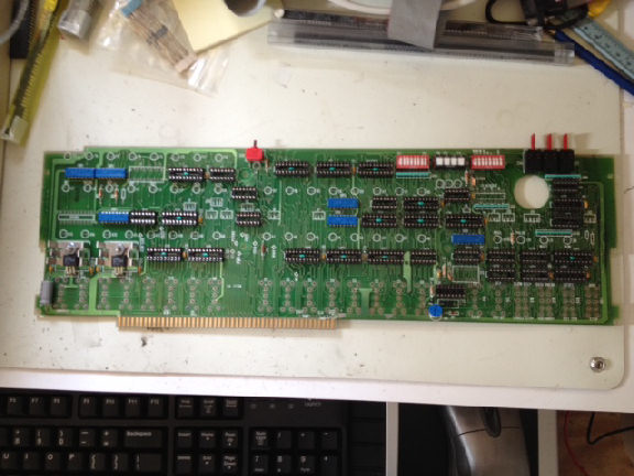
Picture shows front panel PC board, with mounting locations for switches.
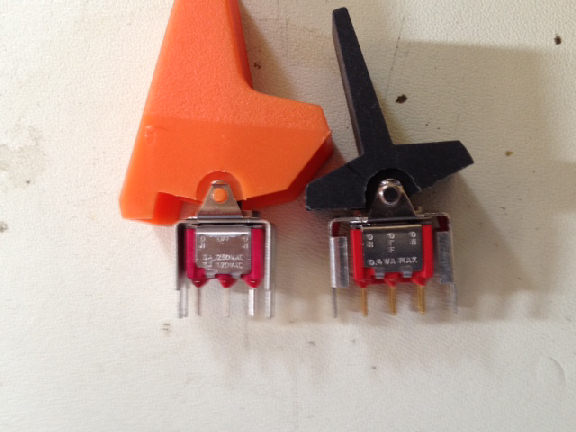
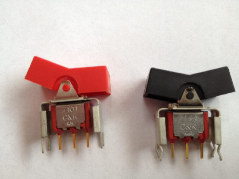
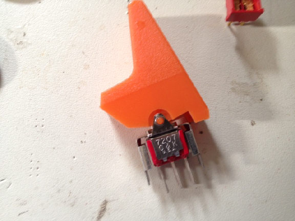
One of the switches I got from John King and one from digikey, I put the orange Ithaca handle on the one from Digikey. Notice end-to-end length of V bracket is wrong.
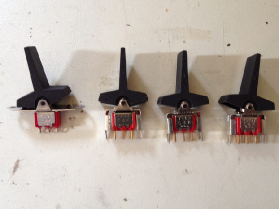
Various switches I got with the kit from John, or imsai.net.Leftmost switch is from imsai.net site, they had no handles. - Kip
Herb wrote: I did switch work on an IMSAI last winter. I checked, I don't have photos of the switch rebuilding work I did. I also checked my photos of the Ithaca work I did in 2009; I didn't have photos of the actual switches. But I've now taken photos and updated my Ithaca Web page accordingly: Look for the new section "front panel toggle switches". There's now photos of a few of the switches, plus my inspection of all the switches to identify operation and C&K model. - Herb
Kipp wrote June 19th:
[Here's a link to the current C&K on-line] catalog I have been using. The following switch description gives the correct V bracket and spacing to fit IMSAI or Ithaca switch handles: C&K 7105J3V3QE2 is a single pole double throw mom-off-mom switch which I think are used in 2 positions on the Ithaca DPS-1, The other 2 mom-off-mom are 7205 as you have indicated. C&k does not make the 7113 any more so I was going to try 7101 in its place. I found the 7105 listed above at Digikey in single quantities. The V bracket holds the switch handle at it's pivot points and gets soldered to the pcb.
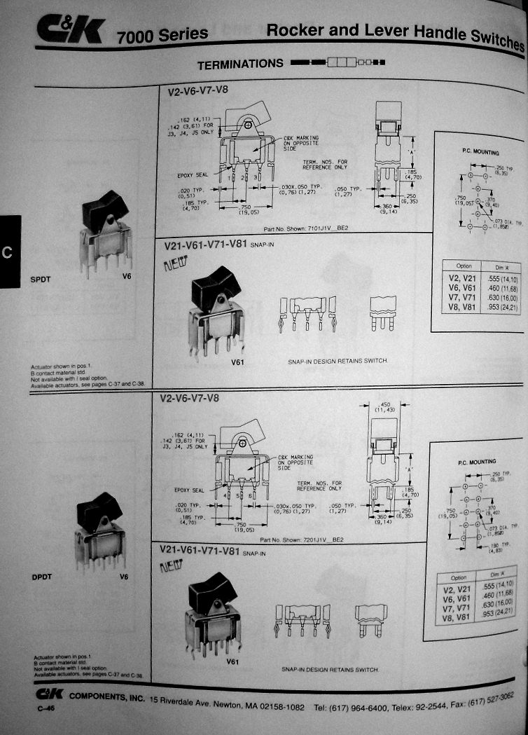
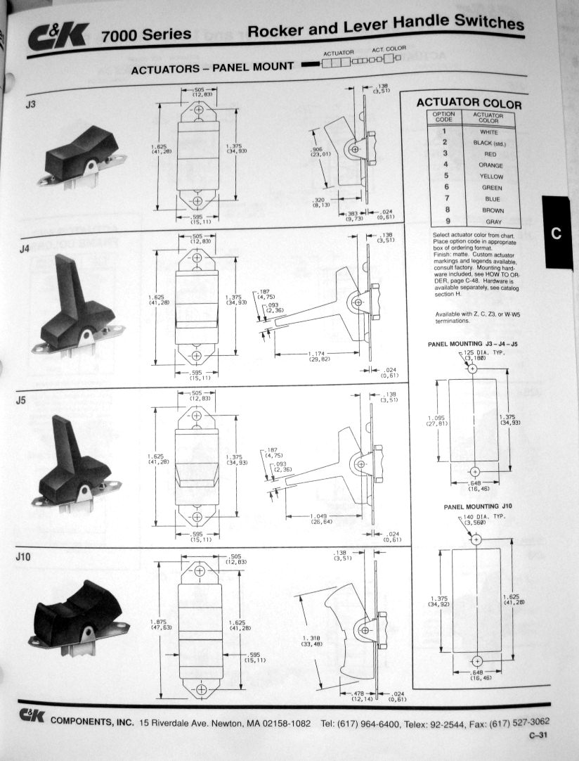
I think that the C&K J3 rocker type is the only one they sell that has the correct spacing. The V6 bracket or V61 bracket are the only ones that place the switches at the proper height. These descriptors J3 and V6/V61 make up the modern C&K part number.
The switches I got from Digikey fit the board, just don't have the right handle mount. John King said to get switches from the IMSAI-2 website, which I did. But those switches are not V bracket, and not pcb mount pins. They are panel mount and solder lug pins.
June 19: Looking at the Ithaca dps-1 assembly document, and the C&K manual, and armed with a dial caliper, I made measurements. Here are the part numbers that appear to correspond to what I measured and observed. These numbers will get you the proper switches with the proper mounts at the proper spacing for Ithaca or also IMSAI handles. You would still need to find the correct handles for either computer.
For the Ithaca:
Qty.       Partnumber.         Description.
16.         7101J3V6BE2.    Address/Data
2.          7105J3V6BE2.    Ex/Ex next, Dep/Dep next
1.          7207J3V6BE2.    Single step/Slow single step
1.          7203J3V6BE2.    Breakpoint toggle
2.          7205J3V6BE2.    Run/Stop, Reset/Ext clear


Notes on the part numbers:
The first 4 digits describe the switch function and number of poles.
The J3 picks the handle type but the only ones with the proper width are J3 or J10.
The V6 picks the V bracket that supports the switch by soldering to the PCB only V6 or V61 have
   the correct size and mounting pin spacing. V61 is a snap fit.
The last 3 letter/number combo picks the contact metal, the sealing material, and the actuator color.
BE2 = gold,epoxy,black. I don't usually care which last 3 I get.
I have 7101J3V6BE2 and 7105J3V61QE3 on order from Mouser, so when they arrive I will verify the part numbers.
HErb wrote: Here's a text document where with Kip's help I break down the part numbers and describe the features and choices. I'm using for my reference, the 1991 C&K catalog, which offered more options than available today.
Here's some photos of the 1991 catalog for reference, and a photo of an Ithaca PC board switch layout.
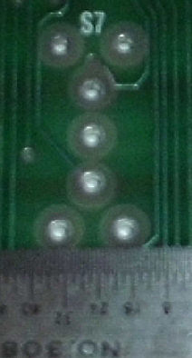
Ithaca switch mount for single-pole. Note the four corner holes for the V-brackets
C&K 1991 catalog, relevant V-bracket switches
C&K 1991 catalog, J3, J4, J5 actuators
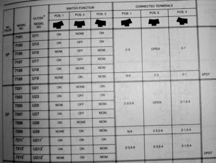
C&K 1991 catalog, 7000 series switch descriptions
- Herb
Kip says: The newer catalog does not show the J4 and J5 handles anymore. Also, the handle colors are limited to 3. The black handled switches I got came from John King not IMSAI.net. IMSAI.net had only red handles, and they are nearly the same cost as the switches. The IMSAI.net switches are all Z switches, solder loops, [and won't fit on the Ithaca PC board]. I called the brackets V-brackets, because that is what they were called in the newer C&K manual (on the page that list all the V J and other designations). Overall your descriptions read better than mine, nice job.
Herb says: I looked around the Web for IMSAI switch descriptions. Tim Shoppa ordered some as C&K 7101-J4-Z-Q-E and 7105-J4-Z-Q-E. The IMSAI-compatible switches I sell have PC board pins not solder-wire loops. I'll have to look at an IMSAI front panel to confirm the PC board holes are large enough to accomodate the loops. But if imsai.net sold Z switches and Tim Shoppa (a smart guy) bought Z switches then it's pretty likely they are large enough holes.
Kip, June 28: These are the switches I ordered from Mouser, the only difference is the bent pins on the V61 snap-in bracket on the right, versus the V6 bracket on the left. So either will work. I also bought another Ithaca DPS-1 and an extra front panel from Jack Rubin. The machine might not have it's bezel, as soon as I get it I'll know for sure. - Kipp
Kip says: One other thing. The original 7113 switches that were used for the address and data on the Ithaca seem to have had only middle and upper positions. The 7101 actually has only upper and lower positions, no middle. While these will work just fine, the switches probably won't line up exactly as the original. (?) I believe that the original had all the switches in the middle so that the handles all lined up across the front, when not actuated.
Herb replies: Good call on the line-up. My original Ithaca, the switches line up when all the ADDRESS switches are UP and the several control switches are in their MIDDLE positions. The control switches that have momentary positions, have them in the UP or DOWN or both positions. But one CAN install all the switches so they line up.
Going back to the part numbers: on my Ithaca, the original switches are numbered as follows. The 7113 is SPDT, on-on. The 7205 is DPDT, mom-off-mom. The 7207 is DPDT, on-off-mom. The 7203 is DPDT, on-off-on. I think that's correct, I can't read off by eyeball all of them. The MIDDLE position of the 7205, 7207, 7203; is the same as the UPPER position on the 7101. The 7203, 7205, and 7207 switches are symmetrical, in that their center position is in the "middle". But the 7113 is NOT symmetrical, it could be mounted either "middle" and down, or "middle" and up. So.....if you can't get 7113, you substitute 7101 and (probably?) lose the "lineup", as you noticed.- Herb
[Since our discussions] I found my paper 1991 catalog and can use your info and of course make visual comparisons. My Ithaca page now describes details of the switches on my original Ithaca Intersystem.
I've done two things when replacing various C&K switches. One, I found some surplus or even used ones, hamfests and so on. Two, I've actually DISASSEMBLED newer and broken switches, to use the contacts from the new to repair the old. I did that for an IMSAI this winter. It's a little tricky but possible.
Cherry and NHK had some switches that might do the job. It's all about the length of the lever, to find one that works with the "paddles" for IMSAI or Ithaca.
Here's something about what I've learned on repairing C&K switches and compatibles.
I don't suggest swapping parts from different BRANDS, unless you can afford to lose a switch to find out the parts are compatible. Work with different MODELS of C&K switches, or work with physically exact duplicates. As for describing the disassembly - that's a lot of work to document.
Essentially, the C&K switches are assemblies held together by the external metal housing, which has metal tongs on the metal housing, to hold to the plastic switch body. Bend back the tongs slightly and bend the housing slightly open to disassemble. To reassemble, bend the housing back slightly; then open it under tension to insert the reassembled switch body. Then close the switch housing and bend the tongs to hold it together.
As you described, the "V bracket" is what C&K calls the the metal U-frame around and on top of the switch, that solders to the PC board, either side of the switch solder pins. YOu may have to use "bodies" with this V-bracket, to assemble from other switch parts the switch assemblies you need.
"Rebuilding" these switches well is in my opinion, a matter of "mechanics feel" and observation. I suggest you examine, assemble and disassemble some switches until you get that "feel" and know what you are or will be looking for. It's fine-scale work, I've done it enough that I'm reasonably clear about what I expect a working switch to do, feel and sound. I mentioned swapping the toggle mechanism, because it seems to be "doable",. Yet it would likely not occur to some people to even TRY.
Otherwise, get some old used switches that haven't been used a zillion times, or some unused old stock. - Herb
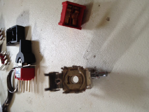
switch guts removed from frame. The hole is where the switch pivot ball sets. It seems riveted to the V bracket, it does not look like it can be separated in a way that would allow it to be reused. This means that I can only swap double poles to double poles, singles won't fit in double frames.
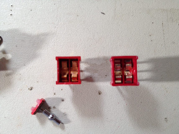
the difference between upper mom-off-on and the bottom mom-off-mom is the shape of the contacts in the switch body, they just sit in the bodies unfastened. [The contacts on the switch lever are shown to the left and below.]
this is the guts of a 7205 installed back into the frame of a 7207. It does work!
- Kipp
Other colleagues of mine in vintage computing, have found themselves reassembling old switches, in order to maintain the original switch hardware on their systems under repair. In 2015, Doug Jones and others are repairing toggles on a "straight" PDP-8 from the late 1960's. They've been informed by another PDP-8 repair project by David Gesswein of pdp8.net. Doug tells me, he's using some DeOxit product in his work on switches, noting: "Right now, I'm putting off the problem of disassembly and rebuilding the front-panel switches, hoping we can wash and and clean them by injecting solvents and then grease using hypodermic oilers. The mechanism is exposed enough that this should (just barely) be possible." Result will likely be on his Web pages.
Copyright © 2015 Herb Johnson