![[H89]](h89_vid_top.jpg)
This Web page last updated June 21 2016. copyright Herb Johnson (C) 2016. . In early 2016 I obtained some CDR brand boards for the Heath Zenith H-89; two CDR floppy controllers, one CDR memory expansion. I'll describe how I repaired and configured some H89's to make use of them. I"ve worked on H-89's before and other Heath/Zenith computers: Check my Heath Zenith computer Web page.
But for these rebuilds, I have specific pages:
some CDR brand cards for the H-89; a summary of other H89's I got working.
This Web page is my "third" H-89 which I repaired for develoment, but
Here's the "fourth" H-89, with boards from this #3 system, which became my development system.
And this Web page is about moving files to the H89's hard-sectored diskettes under CP/M.
- Herb Johnson
late May 2016: I didn't want to disturb the floppy controllers on working systems. They are useful as they are for backup and for use during tests of the CDR boards. So I decided to rebuild a 3rd H-89 from my accumulated parts and nonworking systems. In May I chose a candidate chassis which at least had a good power supply and seemed in good shape. No video, no beeps, no obvious CPU operation. But when restored the keyboard cable connection, I got a beep on control-G (bell) in local mode. This was a good sign.
The 2650 terminal card appeared to function, because 1) the ^G (Bell); and 2) I could see composite video and sync signals from the card. But the video display card didn't produce any display, and the CRT filament wasn't lit. No CRT filament mean no flyback operation, no high voltage (the CRT filament is tapped from the flyback transformer).
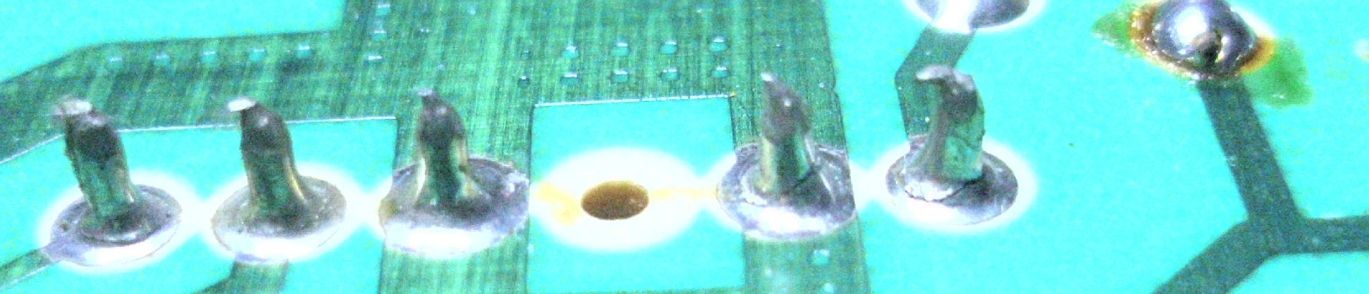
Here's the 2553 video card assembly. I considered the HV transformer on the video card might be at fault. HOwever ohmic comparisions to another HV tranfformer showed no differences. But when I flexed the cable carrying sync and 63V power to the video card, I heard a "click" near the flyback, and the connector felt loose. Sure enough, very close inspection of the video card Molex connector showed cracks in the solder joints.
Resoldering the joints on the video card, was all I needed to restore the video display in local mode. This was not a simple task. I had to remove the video card, which meant I had to remove the CPU board and the CRT itself. But it's all screws and connectors in this H89 model. Earlier models of the H19 used soldered wires to the video board. In due course, I disassembled, soldered all the Molex pins, reassembled, and I got a display of characters in terminal (local) mode. For some reason, I had to adjust the horizontal position trimpot to get the correct display.
But a day later, the video display failed again, no filament visible. That suggested a failure on the terminal card. I noticed the -12V TO-220-cased regulator was very hot. Ohm tests of the output showed a short: a 2uFd tantalum capacitor shorted. I replaced it with a 3.3uFd and it restored operation.
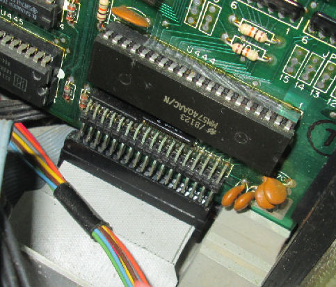
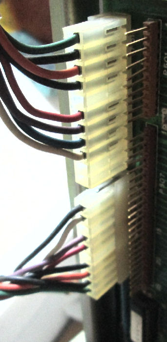
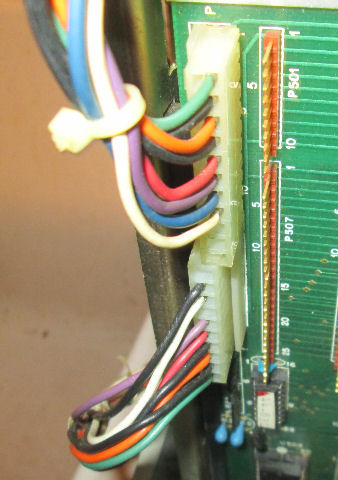
But I could not get the 3615 model CPU card to run. I could see the DC voltages were good; the lower address lines on the I/O bus were wriggling; reset was working. Now, I had already noted the 3615 CPU board uses 11-pin Molex for the power and video lines; but the 2650 video card uses 10-pin Molex connectors and a separate wire for composite video to the CRT card. I had to trace those lines carefully, to confirm the cable "converted" correctly between the terminal 2650 and the CPU 3615 cards.
I had one other 3615 board to try; it was no better. So I wanted to try a 2208 model CPU card, but it had 10 pin Molex connectors. I confirmed the lines "connected" and the DC lines were correct on the Molex connector. But with the 2208 board in place, the CRT filament failed to light - that told me I lost sync again, or worse. Eventually I read the schematic for the 2208, and found the video lines were moved over one pin. At a later time, Lee Hart explained this change in H-89 models.
![[H89]](h89_hart_2208_2.jpg)
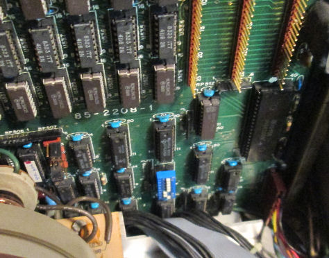
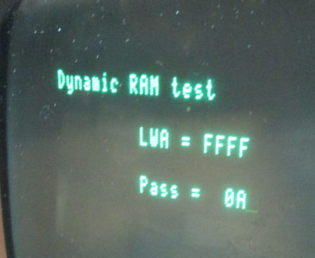
So I rearranged the Molex cross cable to run the 2208 CPU board with pairs of 10-pin connectors. (Note the 11-pin female connectors overlap.) On reassembly, I was greated with a garbled "prompt" on the screen! That said the CPU board was working but was not at 9600 baud. Some changes to the CPU board DIP switch eventually got me into RAM test display on power up; more DIP toggles got me into boot mode. From there I could command the MTR-90 ROM monitor.
I tried this particular 2208 CPU board, as it was purchased from Lee Hart many years ago as a stand-alone CPU board, wired to a power supply and serial cable. I had disassembled it some time after that but kept the board for obvious reasons. Lee had reduced the board to 32K; I had to restore another RAM bank and add a 16K RAM card. Also, he had pulled out some IC leads to be I/O pins; I put those pins back in place. A couple jumper changes, and the board was back to 64K operation again. It seemed to run several cycles of RAM test successfully, as of May 24th 2016.
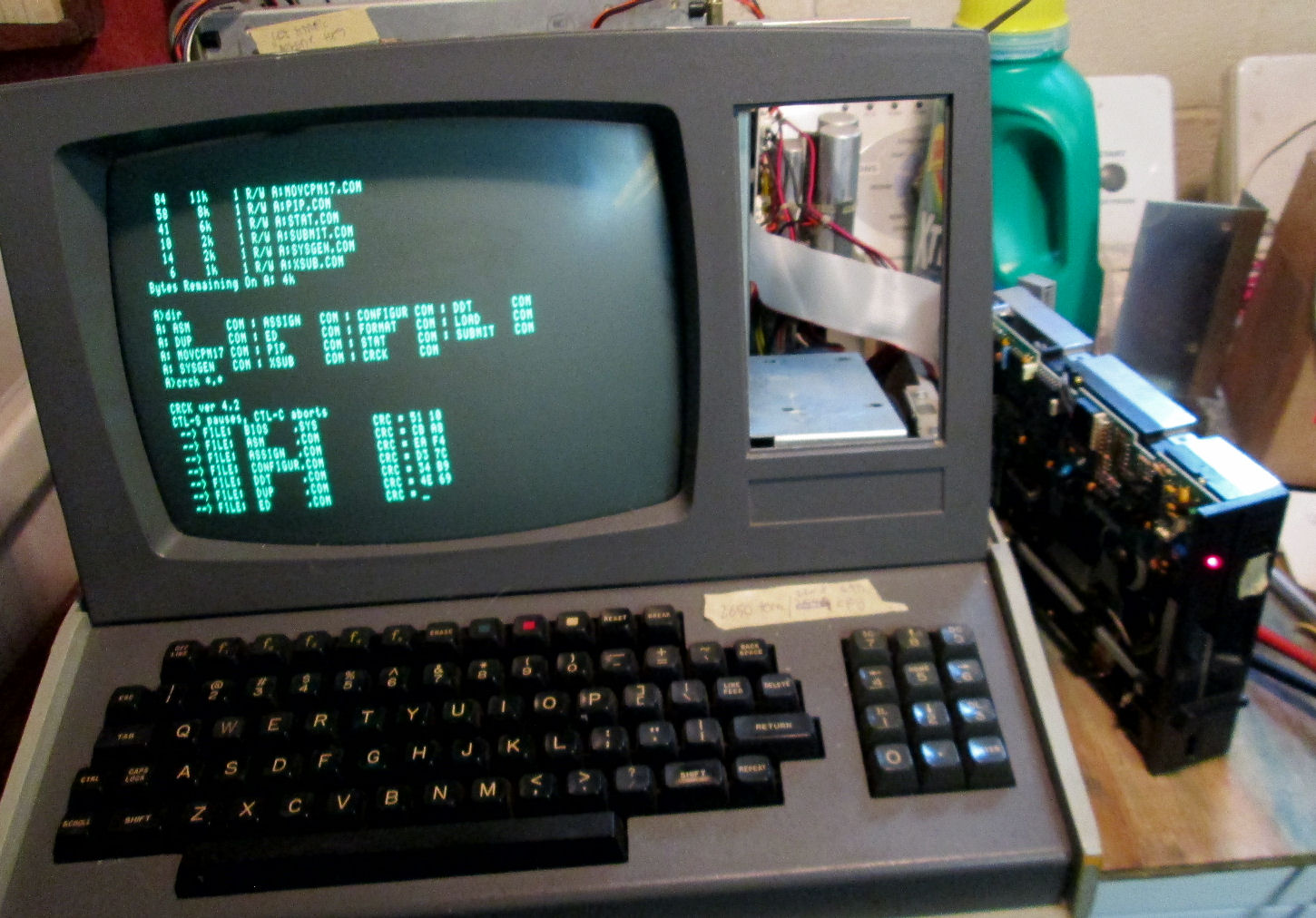
In later days of late May 2016, I continued to work on this 2208 CPU board, adding a hard-sectored disk controller and of course a floppy drive. My other two H89's can read and boot from hard-sectored disks, so they confirm I have bootable and useful diskettes. I tried two floppy controllers, on a floppy drive tested on another non-H89 computer. IN either case, the drive did not appear to seek.
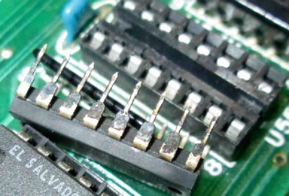
I considered if the problem was bad contacts in the IC sockets. Examination of TI brand TTL chips shows the blackend pins that seem to be common for 1979, 1980 production. I used a brass brush to clean the dark material off. The board functioned in the same way, no change. Also: there's a number of boot commands for the monitor: B(oot) and some number, or B(oot) S(d) and some number. B-SD-2 seems to be the combination I need.
Lee Hart told me by email, to check for a "Write Protect Resistor [for the floppy RAM chips]. A 4700 ohm pullup resistor is required between pins 1 and 12 of P512. This resistor is provided on H-88-1 hard-sector controller board." I did not see the resistor. Lee suggested verifying RAM write, by the monitor commands "Radix Hex; Out 7F,80 ; Substitute 1400, 1401, 1402" to verify writable memory. I'll use an ohmmeter later to verify the pullup to +5 volts (pin 1). Lee noted later, "It's not needed after CP/M has booted, because it turns off bank 0 memory and runs in a pure-dynamic-RAM memory map."
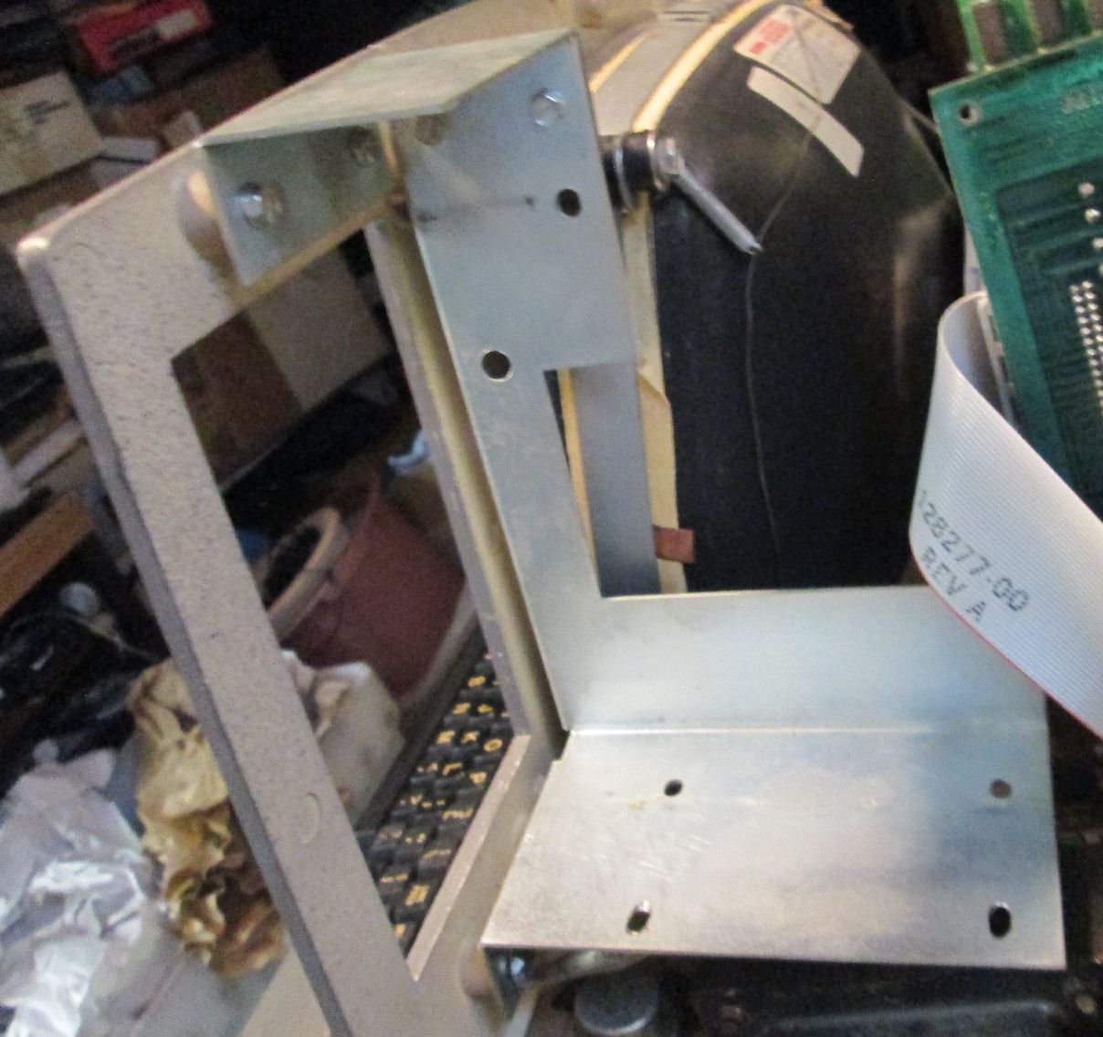
Another issue is the H89's large electric and magnetic fields around the CRT. You need a metal cage around the floppy drive to shield the drive. Read this linked section for more disucssion. And in fact...when I mounted the floppy drive outside the case, I did get some head seeks, and later was able to boot (and crash) CP/M. So I obtained some of the brackets and covers from a parted H89, and built up a metal cage around the floppy drive. Because some of the aluminum taped shielding was flaking off, I covered it with transparent tape. (I removed it from the screw holes to make electrical contact.)
Note: later, Lee Hart pointed out that the floppy-drive bracket screwed into the case, was installed "upside down"; I reversed it later. In actual use it's easier to mount the floppy drive from the top than from the bottom. Also that shielding bracket with flaking aluminum tape was not a Heath/Zenith part.
Ultimately I got better results, by borrowing a floppy drive from a working H-89. I was able to boot CP/M with either of two bootable disks. So part of the issue was likely the floppy drive setup or "jumpering". But the results seemed unreliable and inconsistent. Gradually I've resolved those problems, as I'll describe below.
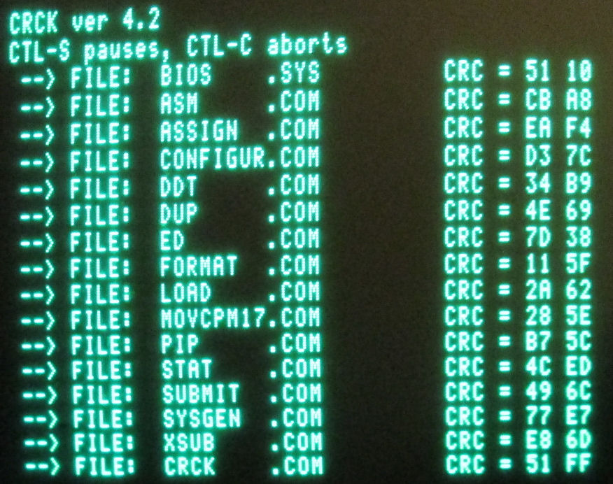
Here's a CRC list for files on one boot disk. The fact that these CRC's are consistent, strongly suggests I'm reading this disk consistently across all used tracks.
June 9-10: On my intermittant drive cable, I put it in a vice to set the connectors better, Meanwhile, I rebuilt yet another 34-pin drive cable (previously used on a IBM PC, had to reverse the "twist"), and put it on the "rebuilt" H89. Disaster - the cable was faulty (I determined later) and it damaged my two CP/M bootdisks. Worse, it damaged a THIRD disk. So I had to find some kind of hard-sectored boot disk to use and copy, without damaging IT.
I tested my two drives on a Z-100 system and they seemed to read soft-sectored disks on those systems. I set up the H89 system with hard and soft sectored controllers to test and copy those hard-sectored disks. It refused to read my previous disks with either drive - I concluded the disks were damaged. So, I tried to read a fourth CP/M disk, not previously used - it booted once and failed. What's going on here? What can I trust?
So I turned to my other H89 hard-sector only system. Keep in mind, that system has its own floppy drive and cable on it, works OK. I've not messed with this system except to repair it. It blew an AC fuse immediately. Bummer. I fixed it later, I"ll describe the details with that system. After repair, I find that system will boot a CP/M 2.204 disk I pulled out tonight. More luck. Run configure to set it up as a one-drive system, copy two more bootable disks. As it's one drive I have to swap disks back and forth - the H89 supports this configuration and tells you to remove and insert as needed. Result: three working 2.204 disks, all boot OK - I write-protect them and proceed.
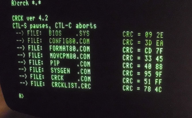
Now I use that same H89 to look at the two diskettes I could not boot from. I run CRCK which examines files. They have numerous bad sectors - the BIOS reports track and sector errors - and of course they wont boot. Some of the files are readable. OK, I've confirmed I had bad diskettes. But now I have "good" disks made on a working system and its drive.
I go back to H89 system #2 (this has hard and soft sectored controllers) to boot using my two test floppy drives, of course booting from the hard sectored controller. I try to boot the 2.204 copied disk I just made. It won't boot that. With either drive I previously used on systems #1 and #2, it won't boot.
I'm about to pull another floppy drive when !!FLASH!! FOOOMMMMM!!!! System #2 cooks a tantalum capacitor. It's on the CPU board, flames up right in front of me. I rush to switch off the AC. On another Web page, I describe my repair.
June 10th. Back on my restored H89 system. I discard the cable I made up yesterday - in the trash. Use the drive cable that worked previously and reseated the connectors. Testing the new-made 2.204 boot disks on the rebuilt system #2 with reseated cable. With each of two drives: the new disks boot on one drive, but not the other. I can read and verify CRC's so that's promising. But I can hear the motor slow down on the nonbooting drive....hmmm...odd...
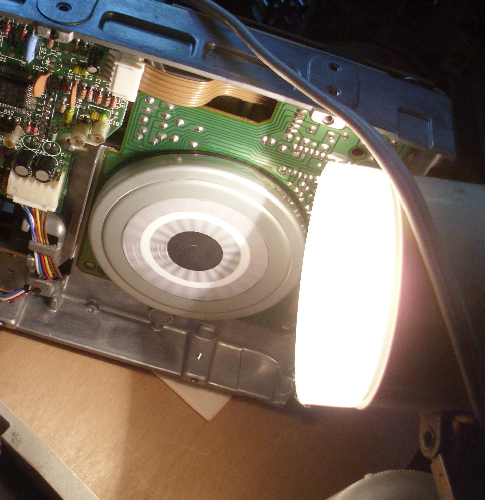
One of the two drives has a "strobe pattern" on the back, that's used to tune the rotating speed. The other drive does not. It takes a neon or incadescent lamp, to show the strobe against the 60 Hertz AC line flicker. An incadescent desk lamp shows me, looking at the strobe circular pattern, the "good" drive runs at speed with disk inserted. I photocopy the strobe circular pattern and glue copy to the problem drive. Sure enough, it slows down when the disk is clamped.
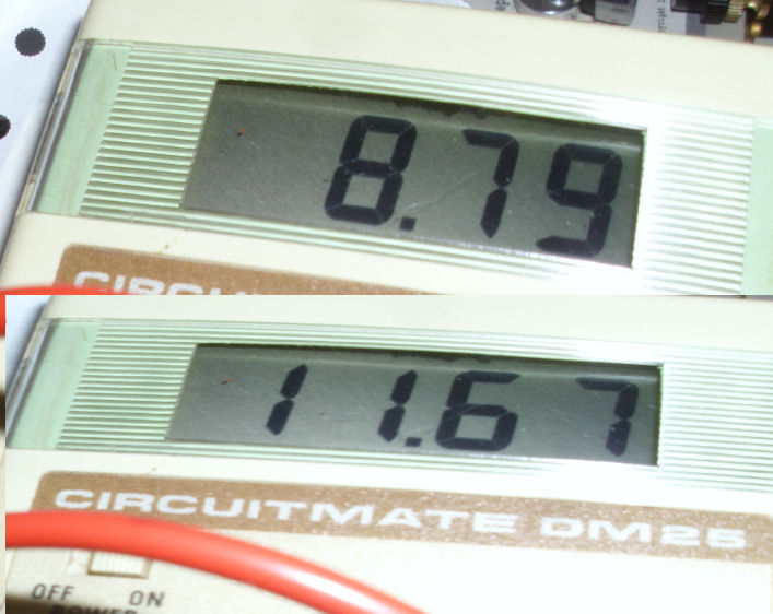
Checking DC power to the faulty drive....5V is steady with disk loaded or not. But 12V drops to 8.75 volts at the DC connector, when disk is loaded . That of course stretches out the data timing out-of-spec. I'll put that drive aside to test later, when I repair system #2. This is odd because both drives ran OK (earlier) on my Z-100, reading a soft-sectored test disk. But some diskettes put more "drag" on the motor than others, that may not have happened on the test diskette.
In discussions with Lee Hart, we determine the problem is with an undersized AC transformer. Read this discussion about H19 and H89 AC transformers for details. - Herb, June 10th.
I checked my H89/H19 "stock". I have a parts H89 chassis with the wider mount transformer as well. But I"m reluctant to tear down two H-89's just to replace a transformer. Fortunately, I also had a "H19" terminal that actually used to be an H-89 with the proper larger AC transformer - but as it turned out, an undersized DC voltage regulator. Here's a link to a Web page, about repairing and restoring that "fourth" H-89 in June 2016.
So I used the CPU board and proper-sized voltage regulators from this system, to complete that 4th system. Meanwhile, with a smaller regulator set obtained from that fourth H89, I will eventually "restore" this former H89 system into an H19 terminal, as it will have the AC transformer and regulators and diodes appropriate to a terminal.
Again - For a summary of the four H-89's I worked upon, check my "H89 CDR" Web page. The point was to check out some CDR brand cards for the H-89. - June 20th, Herb
Clearly I've had numerous failures of tantalum capacitors. They short out and ignite, and melt PC board traces. That's not personal to me of course, it's a consequence after decades of those components. It's known that tantalum caps grow "whiskers" of metal, which short between the capacitor's layers. The shorts create currents sufficient to melt those whiskers, cause more metal to bridge, increasing the melting and current - then ignition of the plastic and actual smoke and flames! I've seen it often enough. See this Web page on yet another H89 repair, when I solve the problem for good
Lee Hart comments: Lee Hart is helping me by using his H89's for parts and to create disks. As I described my disk drive problems, here's what he said. "It turns out that the one you picked was an H19 that had been upgraded into an H89, but still had the original H19 power transformer. The H19 transformer has a wimpy 12v winding, as it only needed to power the RS-232 drivers and a few ROMs. Its voltage sags markedly if you use it to power a disk drive! [I had an H89 with the same transformer,] so I was having disk drive problems as you described!"
"[Also:] Heath used a 7812 12v 1.5amp TO-3 regulator on early H89s. That turned out not to be big enough (some drives needed more). So they changed to a 78H12 12v 5amp regulator. "
"The H19 and H89 transformers look the same, but the H89 transformer is [wider]. Look at the bottom of the case: There are 6 holes to mount the transformer. The H19 transformer uses the 4 inner holes. The H89 uses the wider 4 holes." - Lee Hart, June 10th. Sure enough, my H89 that lacks 12V current drive for the floppy, has the "narrow" mounted transformer. My other two H89's on this Web page have "wide" mounting, with the screws farther apart. - Herb and Lee, June 10 2016.
Herb: You pointed out I needed a Faraday cage around the floppy drive - the different drive probably faced away from the CRT. So I'll make up a shielding box of some kind, and that should do it.
Lee Hart: Heath's original shield was a U-shaped piece of tin, covered with double-stick tape, and with thin copper foil stuck to it. The iron provided magnetic shielding, and the copper foil electrostatic shielding. It attached with two screws on the top of the disk drive.
Heath's later (better) design was a thicker steel 4-sided box. One unusual feature: this box was grounded to the ground pin of the AC connector (earth ground). But it *did not* connect to the body of the disk drive! The inside of the steel box had double-stick tape and "fish paper" so the drive never touched metal-to-metal anywhere.
The drive mounting screws had insulating washers between their heads and the box. The drive then got its ground via its 4-pin power and 34-pin ribbon cable grounds. - Lee Hart, May 2016
Another suggestion from Lee Hart: sometimes the CRT filament fails, because the high filament current needs a low ohms connection. Cleaning and physically tweaking the CRT socket and pins may be helpful. But as I told Lee: when the terminal card can't deliver sync or video signals, the flyback (horizontal) transformer doesn't operate - and that provides current to the CRT filament. However it's possible I tweaked the CRT connection as I removed and restored the CRT and video card.
Lee Hart volunteered this description of the cabling differences between the 10-pin and 11-pin versions of the H-89. - Herb
Lee hart - "The descriptions and photos are of an H89A (later model); not an H89 (early model). Late model H-89A's had 11-pin power connectors on the TLB (terminal logic board)and CPU boards, the piggy-back board on the video card, and other small changes. Here's what those changes were on the power connectors:
       H/Z19          H/Z19A
       H/Z89          H/Z89A
10-pin    color    ll-pin    function
------    -----    ------    --------
   1    green       1    -18v
   2    black       2    ground
   3    orange      3    +18v
   4    black       4    ground
                    5    * KEY *
   5    red         6    +8.5v
   6    violet      7    vert.sync
   7    blue        8    reset
   8    white       9    hor.sync
   9    black      10    ground
  10    yellow     11    video
Note: When Heath went from the early to the late -A models, they added a pin and made it a "key". [A plug was put in the female connector pin, the male pin was removed.] So, the power connectors could not be plugged in wrong. Pins 1-4 stayed the same. Pins 5-10 shifted to pins 6-11, and pin 5 of the 11-pin connector became the "key".
*BUT*, someone at Heath forgot to change the schematic! The early H89A schematics still showed 10-pin connectors and pinouts, when in fact the TLB and CPU boards boards had 11-pin connectors (with the new pinout)! The above wire locations are correct; not the ones on the schematics that show only 10 pins! [Later, the schmatic was revised, I believe it was called the "Z-90" at that point. - Herb]
To reduce RFI, late model H/Z-19 and H/Z-89 connected a shielded cable directly to TLB pin 11 (video). This cable ran down to the brightness pot on the back panel. Another shielded wire then ran from the pot to the piggyback board on the video card." - Lee Hart