![[H89]](h89_4_chassis.jpg)
This Web page last updated date June 24 2016, link added May 7 2018. copyright Herb Johnson (C) 2018. .
In Summer 2016, I'm repairing some Heath Zenith H89 computers and this is the fourth one I'm working on. Lee Hart is proving some assistance by email and his H89's. We are both working on the issues of burned-up tantalum capacitors. Here's a link to a Web page, about some other H89's in repair and use for May-June 2016. Thanks to Lee Hart, for his work, disks, notes and commentary, which I've added to this Web page.
In 2011, I had similar high-DC voltage problems due to high AC line voltage and tantaltum caps, on a S-100 system; follow the link for details.
Since repairs I started to use this H89 for actual work. For instance, I found ways to move files to the H89's hard-sectored diskettes under CP/M. Of course, you can't copy H89 hard sectored disks except on another H89. How do remote owners exchange files without mailing rare disks? See the linked Web page, for how H89 owners dealt with that, and how I'll some files moved over. - Herb Johnson
This H-89 (later identified as an H-89A) was "downgraded" to a terminal so it only has the terminal card. But it has the AC transformer with "wider" mounts, so it has more 12V current capacity than the H19 "terminal" model. I discuss that on another H89 Web page. So I'm restoring this unit, back to an H89. However, it had no video display and no CRT filament. On further inspection, in local terminal mode it DID respond to Control G with a "beep". The terminal card was set for "key click", each key provided a click on the audio speaker. So chances are the problem was in the video card.
An oscilloscope probe of the horizontal, vertical and composite video lines from the terminal card, showed normal signals. So I traced the signals along the cable to the video card and to various circuits. I found the horizontal sync signal got to the Molex connector of the video card, but no further! This suggesed to me a broken connection at the Molex, a problem I found with one of the other H89's. Without horizontal sync, the high voltage flyback is not energized and there's no filament voltage or high voltage. Therefore no visual display at the CRT.
To repair the video board under the
CRT, I had to remove it. To access the card, I decided to remove the terminal board and frame; to remove that I needed to pull the power supply board
and heatsinks.
![[H89]](h89_4_power_1.jpg)
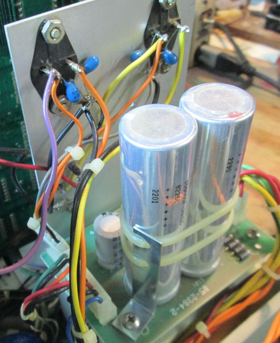
Here's a photo of the power supply I found in this H-89A unit. There's an additional connector with four pins, for DC power to the regulators. This power supply has four diodes for the 5-volt supply; some models use a full-wave bridge mounted on the heat sink. I traced those lines to my satisfaction. This linked photo shows the base under the power supply, and to the upper left is the video card and its
aluminum bracket with mounted regulators. Now I'll have access to the screws which hold the terminal/CPU vertical bracket.
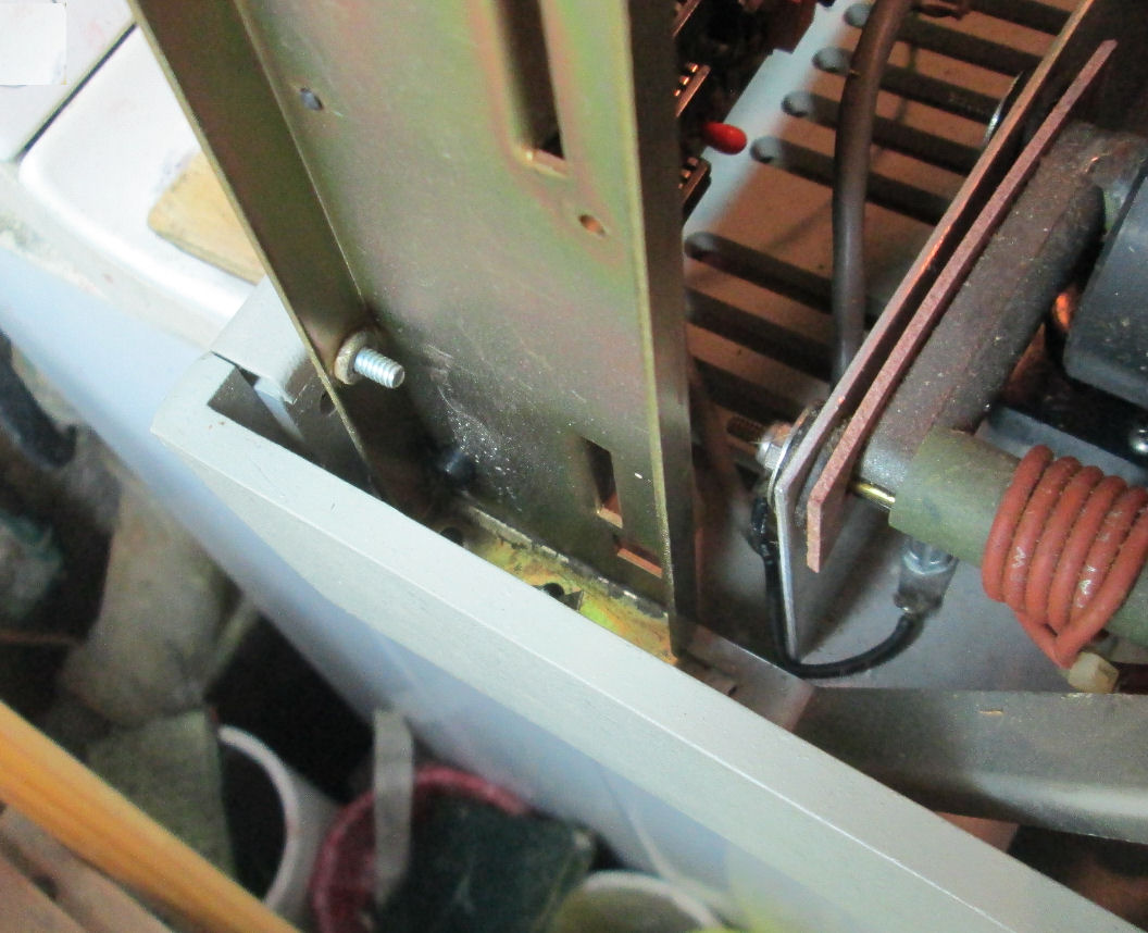
This linked photo shows the left bracket for terminal and CPU logics.
![[H89]](h89_4_video_bd.jpg)
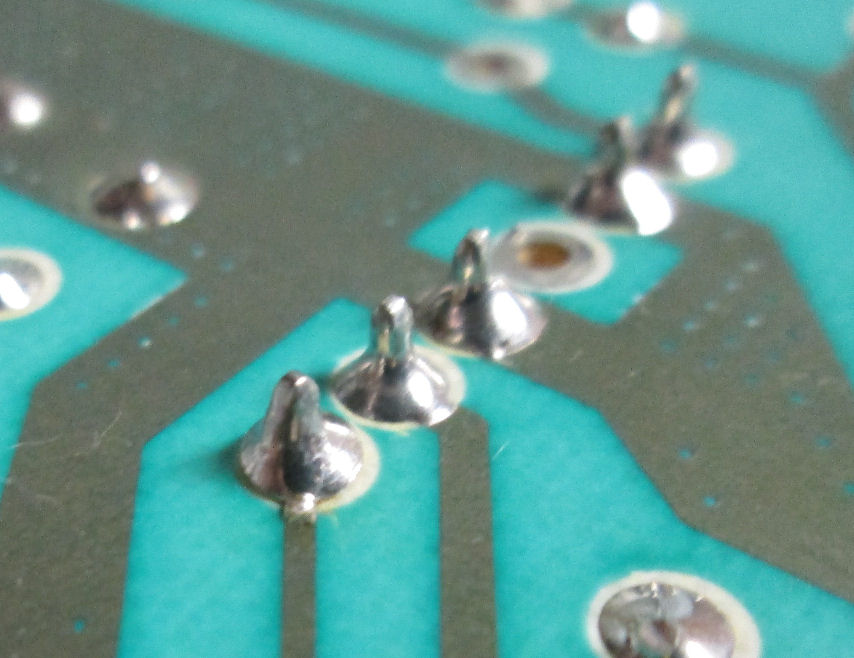
To pull the video board, I removed the terminal card and brackets as one assembly. This gave me access to pull the video card 85-2553-2 from behind the chassis. The video card has a small daughter card for incoming composite video. The high-voltage flyback transformer is mounted in the upper left. The connector for +65V power, horizontal and vertical sync is a 6 pin male Molex connector of five pins near the center of the photo. A photo of the PC side of the connector, doesn't show that the first pin (nearest the bottom of the photo) has a broken PC trace at the solder eye connection. When I desoldered the pin, the PC eye around it just lifted off. Clearly it was overheated or otherwise was pushed off the board. I repaired the connection with a loop of fine wire, soldered to the rest of the PC trace. I resoldered the other pins as a precaution, scraping into the trace at each to reinforce the junction.
When the video board and terminal boards were reassembled into the H89, the screen displayed normally, the filament
was lit and there was high voltage. - Herb, June 10 2016.
P>Later, June 21st: I pulled the terminal-board assembly, to access and remove the video board from under the CRT. On a previous repair, I pulled out the CRT to get access. That was physically complicated and I took some risk of damaging the CRT (or myself). Lee Hart suggested later, to remove the LEFT diagonal brace and vertical bracket only, and extract the video board that way. - Herb
June 15: I moved a working CPU board from an under-powered system, to this H-89A chassis. To do that, I had to build or rebuild the DC Molex cables to "mate" the boards. The video board uses the 11-pin Molex connector; the CPU board uses the 10-pin Molex connector for DC voltages and to forward the video signals to the terminal board. Also the composite video line had to be moved. Also, I fixed the regulator wiring so the unregulated 12-volts and regulated 5-volts (now with unregulated 9-v input) went to the 4-pin Molex cable direct to the CPU board.
After that work, I gradually powered the resulting system with my Variac, to verify that proper DC voltages were getting to the CPU board. They were - but as I brought up the AC voltage - *crackle* *smoke* - and I shut off the Variac. Pulled the CPU board to look for where the damage was. The terminal board looked clean and no components hot to the touch. I had to inspect the pulled CPU board under bright light, to visually find the damage. It was a cooked trace, the unregulated +12V from the 4-pin Molex to the two regulators on board, It was blackened and brittle - just like a previous tantalum short and failure. The trace opened up and will need to be wired over.
Again - one of the tantalum caps shorted out, probably as the CPU sat unused for several days. I've had to replace these same caps on other H-89's. I threatened to replace all these tantalums BEFORE making the swap - now I gotta. And look - it's populated with blue 2.2uF tantalums rated at TWENTY VOLTS. two-zero. For an unregulated 19 point something volt DC supply! For unregulated +5V, about eight-nine volts, a 20-volt cap is adequate margin, but it's not for the +12 and -12 unregulated lines. But they still short in time, so I'll replace them ALL.
![[H89]](h89_4_newcaps_1.jpg)
June 16th - on the CPU board, I replaced eight of the 2.2uF/16V caps, with 2.2uF 50v ceramic caps. These are across the regulators at the top of the board. The +12V inputs are unregulated voltages, not current-limited. (And that's why the 18-20V PC board trace became a "fuse".) Other voltage regulators on-board are from regulated -5V from -12V, so they are current limited. Desoldering and soldering the caps was uneventful, it was easy work with the board on-the-bench. Also I wired-over the burned out trace, with wire-wrap wire. The photo shows the new blue ceramic caps, and the blue wire on the Molex connector.
I considered replacing the tantalums on the TO-3 regulators on the heatsink. They are 4.7uF 35V. I may do that, but for now their voltage rating is well above voltages in use (under 20V) and that provides some safety margin - I hope.
I powered up under the Variac, raising the AC voltage and looking for shorts (no DC voltage) or unusual voltages (Molex connectors incorrect). There were no mishaps. At 90VAC approximately, the terminal came to life and responded with CTRL-G beeps. I had to power-cycle to reset and operate the CRT - the filament came up and the display showed characters in local mode. taking it out of local mode, the CPU board (fortunately) responded fine. RAM tests were OK, the floppy memory switched on (out 7f, 80).
Next step will be to swap the floppy and serial back panel from the "old" H89 to the "new". My "parts" H89 is actually an H88 - it has the square Molex connector for cassette! And no holes for floppy cables or other serial ports. Swapping the back panel from the other H-89 was uneventful, just a little tedious, requiring attention to details to avoid jamming cables. - Herb
![[H89]](h89_4_power_4.jpg)
Remaining power supply concerns: 1) the large diodes for +5V unregulated are pretty hot. 2) there's no additional heatsinks on the TO-3 regulators. 3) I did not replace tantalums on the terminal board; but none of them have failed capacitors so far, for some reason.
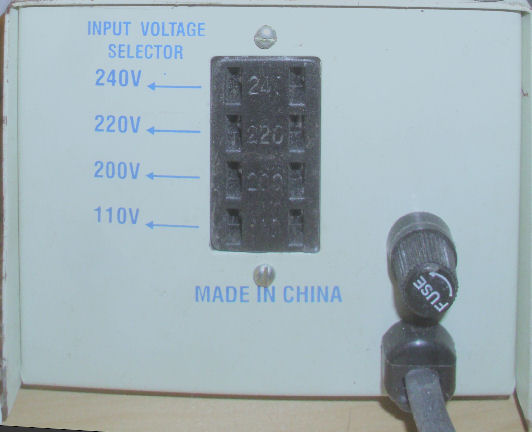
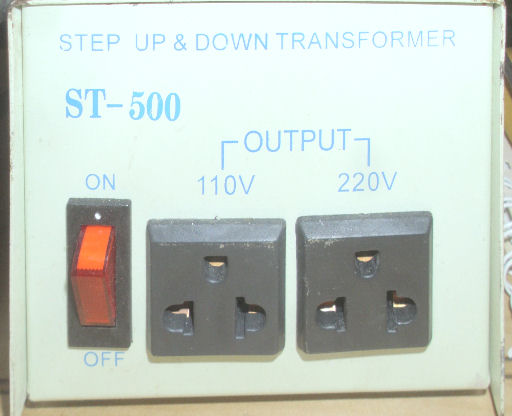
June 16: I found in my inventory, a 110/220v conversion transformer. It has an AC power cord for input; four "jumper" settings: 110 V, 210V, 220V, 240V; and two output outlets for 110V and 220V. The "jumper" is a two-prong AC plug, shorted. So....I set the jumper for 210V, of course used the AC line cord for "input" and used the 220v outlet for "output". So the unit expected 220V in and 210 volt out. Result? input voltage was 120V, os output voltage no load was 110V. My guess is that this 10% drop will drop unregulated 19.X volts down about two volts. It's not a lot but it's something. Otherwise and for testing, I'll use a Variac.
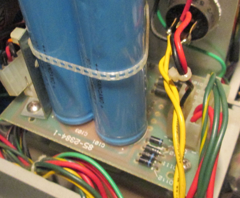
June 16: on operating this H89, I noticed the four diodes on the power supply that likely provide unregulated 5V (probably 9.something volts) are fairly warm. When I add two more logic cards and a floppy drive, they will only get hotter. In the photo of the power supply regulator board they are the four large black diodes between the other two sets of four. Note the heatsink has a pair of holes but no device. PC board is 85-2384-2.
Comparing this to the power supply on my "hard/soft" H-89, I see Heath went to a full wave bridge mounted on the heatsink. That's what is on the "restore" system I pulled this CPU logic from. You can see two sets of 4 diodes, holes for a 3rd set, and in the upper right a circular full-wave bridge. PC board is 85-2384-1.
Note: Lee Hart retrospectively noted, both of these power supplies showed differences in wires and features from "stock" H-89 power regulators. Any used H-89 or H-19 will likely show user repairs and modifications. I made some, myself. Note how I carefully traced wires and PC board lines, to verify electrically correct connections - especially when schmatics did not agree with the physical connectors! See another H89 Web page for more discussion about power connections across H-89 models. - herb
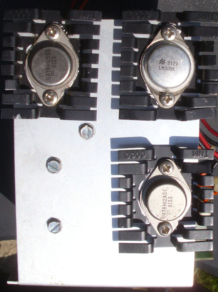
![[H89]](h89_4_newpwr_1.jpg)
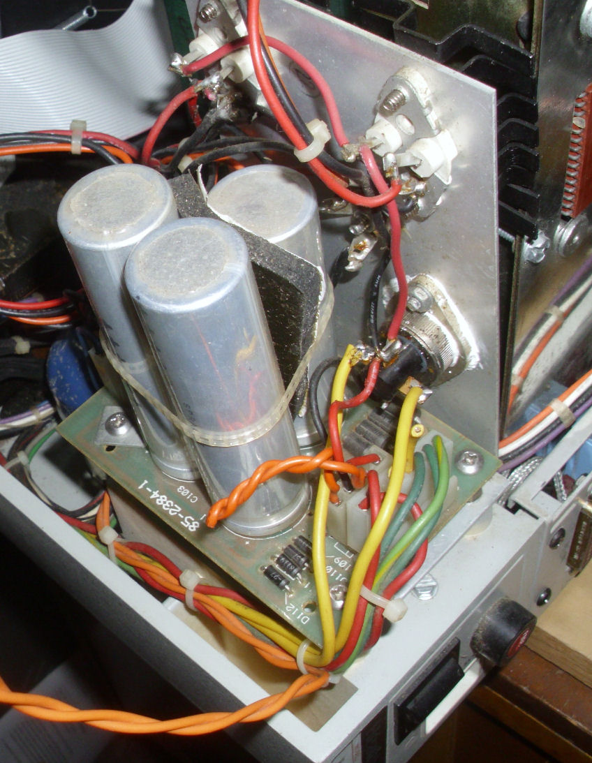
So, I decided to transplant in, the "old" power regulator board from the H89 with the too-small transformer. It has the Heath 5V bridge "stud" and the heatsinked TO-3 regulators. Upon examination, it has the higher-power 78H05 and 78H12 regulators too. The AC transformer connections to either card are the same, except the 9VAC lines are soldred directly to the stud bridge rectifier. In the photo, you can see two taps on the stud are unconnected. The installed photo, shows the yellow wire pair previously on the Molex connector, are direct-soldered now to the stud. Lee hart told me, this was a Heath modification, because too much current on the Molex caused the connector to turn brown and drop voltage.
With the new regulators in place, I brought up the H89 carefully with a Variac, to make sure there were no errors or shorts. I noticed,
as I brought AC voltage up on the Variac, the regulated 5V to the CPU board seemed low. I shut down and measured DC resistance - it was about 150 ohms!
That seemed low, even for a board full of TTL chips, I usually see a few Kohms in the forward-biased direction. But I measured another, working, H89, and the same resistance at the DC connector was under 70 ohms. So I brought up AC voltage, and the DC regulated power voltages stabliized at
correct values (5, 12, 12) at about 100V AC. There's measurements in use, in the description below.
![[H89]](h89_4_newpwr_ok.jpg)
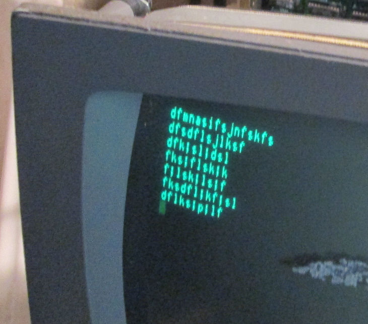
June 20: With good DC power available, the H89 ran RAM diagnostics OK. With the the floppy drive installed, it too operated OK, and CP/M booted up at once on the hard-sectored controller. In the photo, you can see CP/M running a CRCK (checksum) program which reads files and reports a checksum. You can see the top edge of the CPU board, with the top row of tantulums replaced with blue 50V ceramic caps.
June 21: With disks for CP/M and HDOS in hand, I proceeded to make copies of them. I set up an external floppy drive for the second drive, to facilitate copying. By and large, I was able to read disks from Lee Hart and my own former disks, and to format or init disks to make copies. I was somewhat unfamiliar with HDOS, but the SEBHC archives of Les Bird were helpful. A stumbling block: the H89 "likes" to have drives selected at DS2 and DS3 - not DS0 and DS1 as typically on 8-bit systems of 1980. With those settings, under HDOS drive-to-drive copy utilities actually WORKED. ;)
Herb Johnson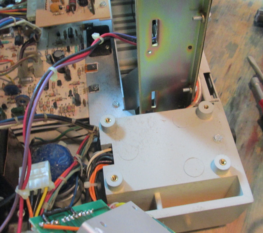