From documents and photos by M. Leighton Greenough, February 5, 2008 & May 19, 2008. Last edited April 27 2010, revision Feb 2 2015 - Herb Johnson.
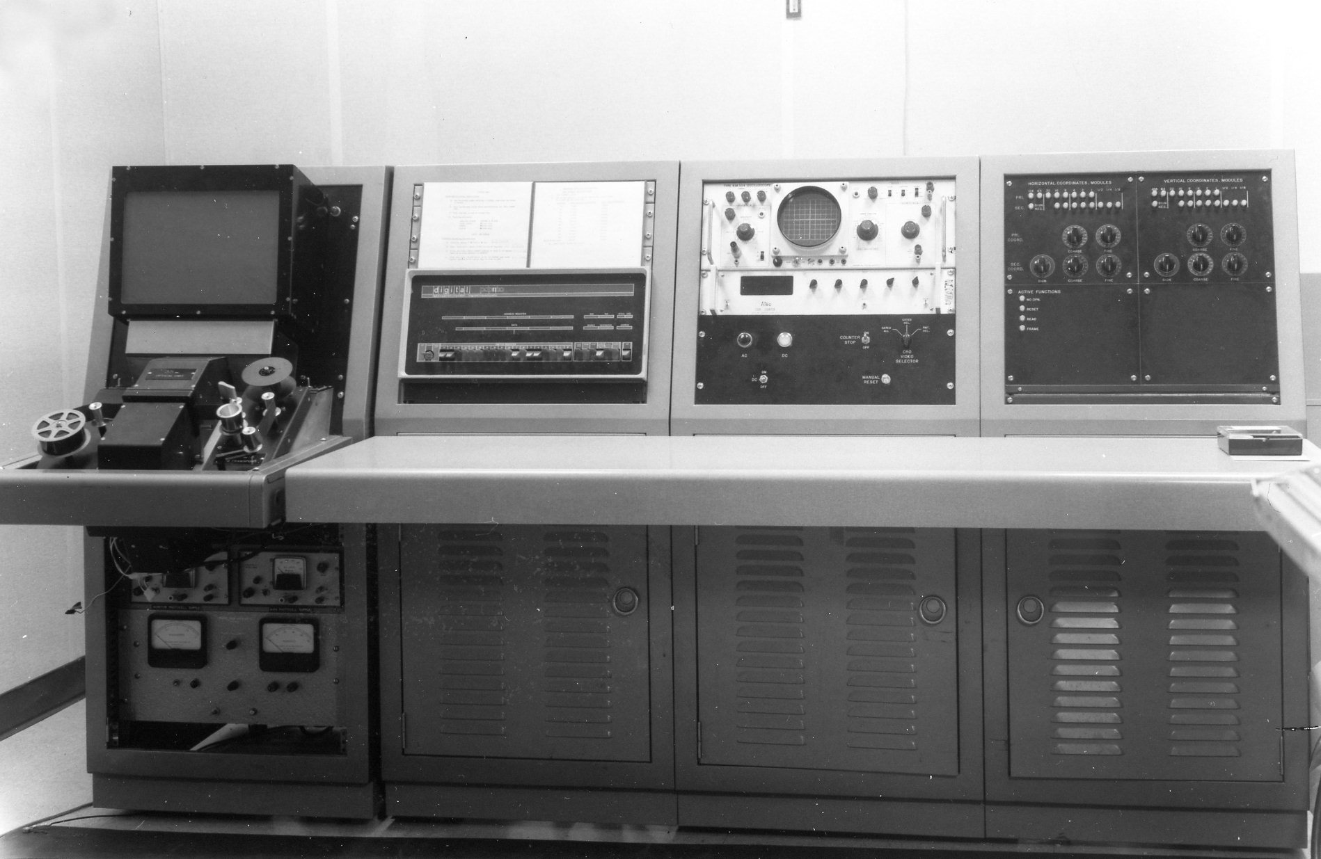
In August 2007, MARCH acquired a PDP-11 system from Mr. Greenough. This particular computer was one with which he was associated while employed at the old National Bureau of Standards [NBS, now NIST.] After retirement, his consultancy work for the Postal Service Research Laboratory maintained that association, leading eventually to its acquisition by Greenough after the project's completion. The document below, from Mr. Greenough, describes his work and the equipment related to that product, the FOSDIC IV.
The home Web page describes the actual 1969 PDP-11/20 system donated to MARCH, with a complete paper-tape based operating, development, and debugging system, Other descriptions of that system will be found on, or linked to from, that Web page. This material was provided to MARCH by Mr. Greenough on Feb 19th 2008. Additional material of comments and corrections were provided by him on May 19 2008. Any errors are more likely mine than Mr. Greenough's, with my apologies. Edits and relocations of portions of this document was done by myself, Herb Johnson. Some edits are identified with []'s. - Herb Johnson
This material was provided to MARCH in 2010 for their use; I retained a non-exclusive right to use. They since lost interest. Please contact me to offer corrections, additional information, or further references. In 2014 I received more FOSDIC information, which I've included in this document.
Herb Johnson
To describe the career of this PDP 11-20, some background may be useful.
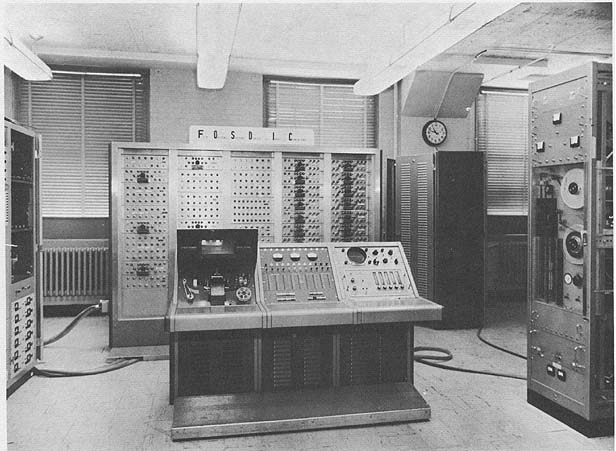
This computer's function was as the driver to a microfilm scanner, one in a family called FOSDIC, an acronym for Film Optical Sensing Device for Input to Computers, which accurately describes its function. The first device of its type was developed in the early 1950's for the Census Bureau for large-scale data entry in decennial censuses. This [particular] PDP-11 came along fifteen years later for use in the system numbered as FOSDIC VI. In the discussion below, I describe some of the projects in which it participated at NBS.
Over a period of forty-five years [from 1951 to the 1990's], fifty machines have been constructed in a series of progressively more refined FOSDIC models. All were [developed by and] employed entirely in U.S. government operations.
[The technology so developed, found its way into later commercial applications and products. Greenough later comments: ] In the late 1950's, several manufacturers came around to explore contract construction. None got involved, which I think was wise of them. FOSDIC III's were considered $250K instruments at the time. Somewhat facetiously, our Census contract [contact?] said he would accept bids from manufacturers if they would put up a bond equal to the cost of the census. There were no takers.
This PDP 11 computer was part of a system originally identified as FOSDIC VI. It was active early in the 1970s, midway in the above time period. The system was used in both on-going and experimental work for several agencies. In 1986 the overall system was no longer needed and was sold to me. Parts of the scanner were incorporated in my machine (the last of the FOSDICs) but the by-then-obsolete PDP 11/20 CPU was put on the shelf.
...I personally built the last [FOSDIC] in my basement shop; it was arguably the the best one. It had a faster computer, with a 486 [processor], also superior optics. It's still there [in 2008], unused since I did a 3000-roll job for the Weather Bureau ten years ago.
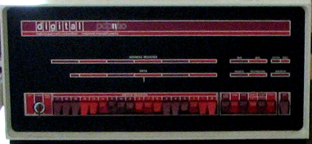
[The exhibited] PDP 11-20 computer was never used as a stand-alone machine. I purchased it for a project in about 1969 for driving the scanner in a complete system and then modified it with the addition of interface circuitry.
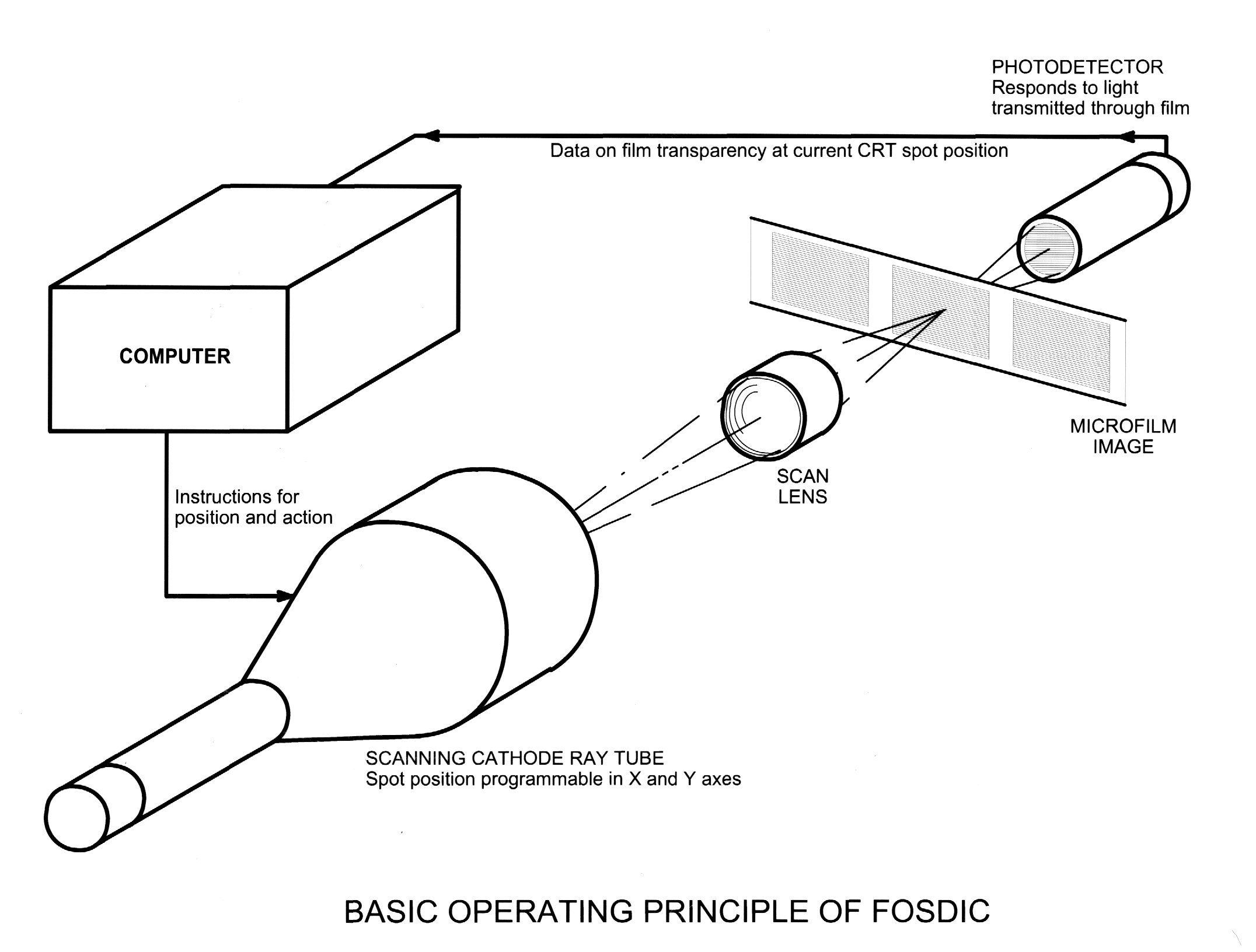
A FOSDIC system consisted of a microfilm scanner directed by some kind of computer. The instruments, of which 12 models were made in all, were flying-spot scanners, differing from conventional devices in being interactive. That is, instead of using a fixed raster grid, the underlying principle involved pattern recognition based upon guiding the scan according to what it "sees". Typical scanned images included census documents, punched tabulating cards and a variety of special applications. Outputs were normally supplied on magnetic tapes to large-scale computers.
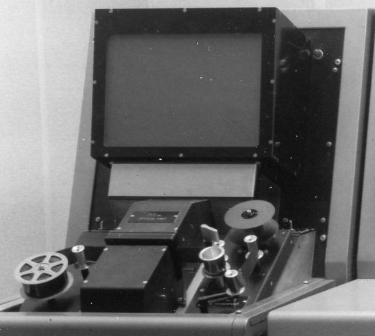
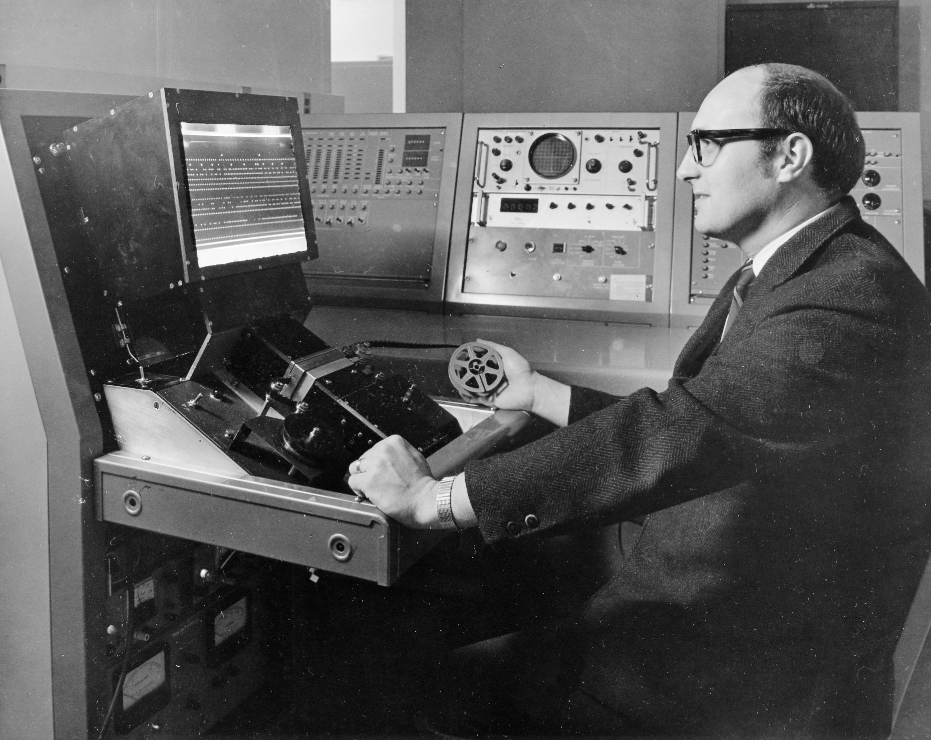
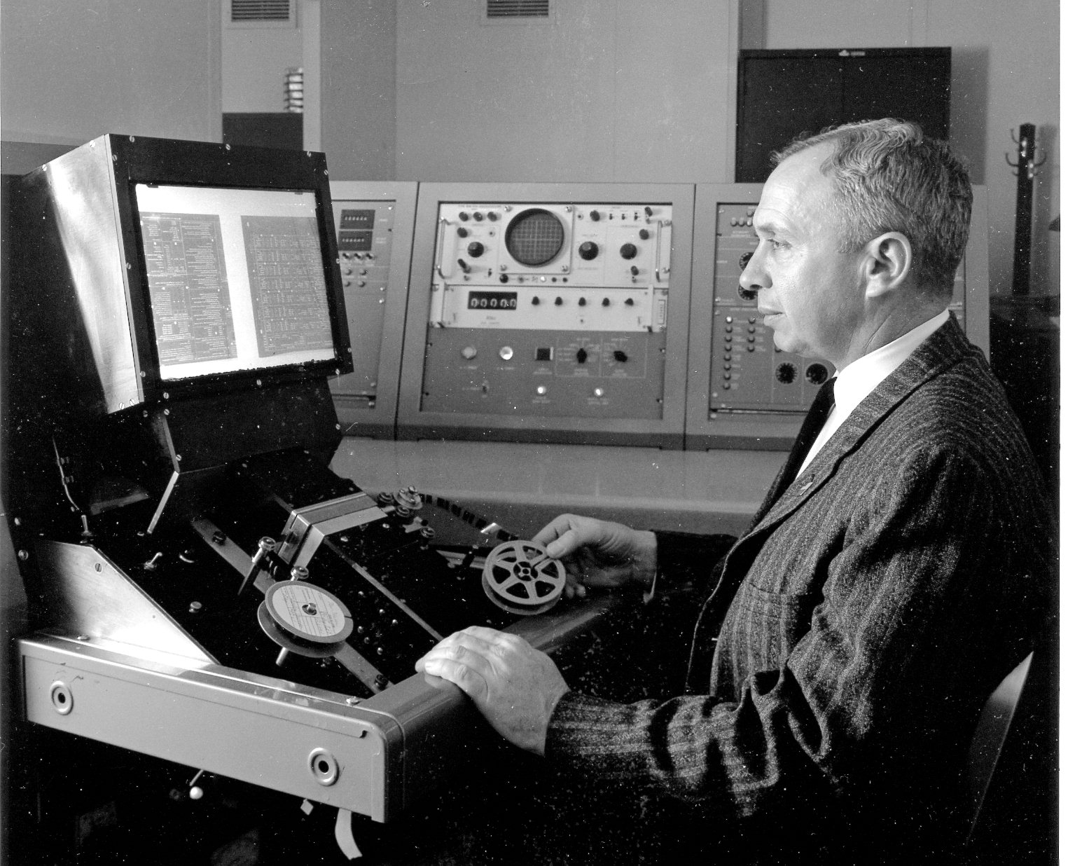
[On the FOSDIC VI system, the scanning CRT and sensor were installed on an otherwise conventional microfilm reader. The film moved between the scanning CRT and the photodetector, each encased in black boxes below the screen, as shown in the photo.]
Development of the first FOSDIC began in 1951 at the National Bureau of Standards in response to needs of the Census Bureau. The agency was in the process of acquiring the first commercial computer, UNIVAC I, and had come to NBS for assistance. It also foresaw the necessity of a process for high-volume data entry for their computer. Assigned the project at NBS, I introduced the adopted approach after experiments with alternatives. The first model, delivered in 1954 and immediately put in service, demonstrated the feasibility of scanning microfilms of specially-designed forms for rapid data entry. New machines of increasing capability were built for each of the four national censuses of 1960, 1970, 1980 and 1990. FOSDICs were the main source of data entry for these censuses as well as for the official unemployment statistics for thirty years. The most recent scanning activity was in 1998 on my own system, a project of several thousand film rolls for the Weather Bureau.
Computer systems for scanner actuation have evolved from analog techniques to full software control. In the original FOSDIC most parameters were set by potentiometers. Later there were hard-wired functions in the scanner called up as desired by the directing computer program. Probably the most sophisticated, and complicated, of all the scanners was the one driven by the present PDP 11. After this system, more of the task of creating scanning and recognition actions was taken over by software. The last scanners became logically simpler, spot-readers but with benefits in precision.
On processing speed: The [later FOSDIC?] machines ran at an average rate on the 1990 census of 22 pages a second. My own [most-recent machine], FOSDIC-GDA (for Greenough Data Associates) scanned at up to 98 punch card images a second. FOSDICs got their speed from not having to make a complete overall scan before analysis. The optical image was the memory, always there [and] ready for examination at will, stationary during scanning.
All FOSDICs had a system for backward projection through the film and scanning lens. This results in a visible image of the film on the face of the five-inch, flat-faced CRT which is in registration with the scanning pattern. The registration is exact because both optical paths go through the single scan lens. Then you can look in with a short-focus telescope and see how well the [CRT] scanning spot is located. It's a big help in program development at the console, providing instant gratification.
The idea of dual optical paths originated with another member of the original team. I refined it in later systems. Most of them were based on Barlow lens systems (image enlargement via a negative lens), letting you have the front viewing screen you can see in picture of the [scanning] machine. The [display] screen gives a magnified version of the film image but does not reproduce the actual scan. I never could come up with a technique for displaying the scan pattern on the screen. For my own system I used a two-lens approach to give quite a good image at 16X enlargement.
The spectrum is fully utilized in FOSDIC optical systems. The CRT phosphor produces blue and near-UV light for actually scanning the film. It is visible through the telescope or the observation window. The projected film image on the face of the CRT is green. On the front viewing screen the enlarged projected film image is orange and red. It's all done with color-selective mirrors and filters, of course.
FOSDIC VI was built at NBS in about 1968 for an agency that eventually chose an alternative approach to mapping and made the instrument available back to NBS.
As a technical note, I should mention that the interface logic to the scanner used memory addresses for the type of action desired and the data to the address as a modifier. For example, to read a column of twelve equally spaced positions, the computer would issue the value 12 into the Read Width memory address. After finishing other tasks, it would wait for the end of a Busy signal.
The scanner-PDP 11 combination saw service of various experimental types for several years. It was declared surplus in 1975 with my retirement from NBS. Shortly afterwards the scanner-computer combination was acquired by the U.S. Postal Service Research Laboratory and I was commissioned to convert it into what was called the Postal Precision Scanner [photo to left]. Conversion was essentially simplification and improvement in resolution. After a period of use the overall system was no longer needed and was sold to me in 1986. Parts of the scanner were incorporated in my machine (the last of the FOSDICs) but the by-then-obsolete PDP 11 was put on the shelf.
EPA Pollutant charts
The Environmental Protection Agency had a collection of plots of certain atmospheric pollutants versus time of day, from which quantitative values were desired. We rigged up a platform containing a pattern simulating the special elements that allowed FOSDIC to recognize discrete images and calibrate for their skew and size. Another part of the platform was the space into which the charts were placed., defined by barrier pegs.
To prepare for FOSDIC scanning, the charts were microfilmed on 16-mm roll stock. The computer was programmed to issue a sequence of commands to initiate specific scan routines hard-wired in scanner circuits. For example the first command would be to move the film to the next chart image and wait for word that the new image was in place. This would be followed by initiation of other routines to perform calibration functions. Once calibration was completed, the program switched to creating a raster pattern of discrete reading positions in a column. At the top of each column a response from scanner to computer indicated the position of greatest signal seen in the traverse. Known scale factors converted the found position to sample value. The resultant table of chart trace positions was thereafter recorded on magnetic tape, one block per image at a time.
This was a relatively straightforward application of the system. Most of the novelty of the approach was in the calibration process to deal with image position, skew and size of the chaart images. With a memory of only 4k bytes, most of the scan detail capability was included in the scanner itself, taking advantage of its sophistication.
NOAA Underwater current meters
This application was carried out at NBS under contract for the National Oceanographic and Atmospheric Agency (NOAA). These meters measured underwater current and direction, recording their derived information as dots on 16-mm movie film. The goal of the scanning was to find the dots and interpret their meaning in physical data. There were about sixteen tracks across the film, with several decoding schemes, Some were nearly static, like binary codes for vane angular position. Another involved counting the number of dots in a given distance along the film to indicate propeller revolutions, hence water velocity. This application required more storage than the EPA project, necessitating subsequent data interpretation. Nevertheless, the process became quite routine and was active for several years until magnetic recorders replaced film units in the underwater instruments.
Pictured at the film scanner is Michael McCabe, an engineer who worked with Dr. Greenough on special projects.
Test bed for Census FOSDIC design
From time to time the scanner-computer system at NBS was employed in checking out or verifying the limits of proposed changes to the machines at the Bureau of the Census. One example was to determine the feasibility and minimum dimensions of a black printed bar to simulate the normal inter-document spacing. This particular feature produced multiple benefits in microfilming and data volume on a page. Most of all it allowed the use of document designs that facilitated the less expensive process of self-enumeration by the public for data collection. To pursue this investigation required programming the PDP-11 for full document reading plus that for bar recognition.
Pictured at the film scanner is Charles Gordon, an engineer who worked with Dr. Greenough on special projects.
Service as Postal Precision Scanner
At the Postal Research Laboratory [in the mid-1970's,] I converted the former FOSDIC VI scanner and computer system to an instrument for creating a database of typical mail. The specific goal was to scan examples of dead-letter mail, which had been recorded on microfilm. For this purpose, I removed most of the special scanning circuitry but retained the PDP 11 with its interface to the scanner. A major change to the scanner was the introduction of a higher resolution cathode ray tube (CRT) for the scanning. This necessitated more detailed action by the computer. The application then required programming the computer to generate a raster of closely spaced positions. The result for each mail piece was an electronic record on magnetic tape as a data base source for evaluating character-recognition techniques.
Dr. Greenough recommended "Look up the "National Geographic" for November 1959, for an article "1960 Census: Profile of a Nation", on the coming 1960 census." These magazines are available at many major libraries, or can be purchased through various vendors for several dollars.
The National Bureau of Standards (NBS) is now the National Institute of Standards and Technology (NIST). NBS and NIST research provided technological leadership in many areas, and also established and maintains standard measures. Their general description of how they developed massive optical scanning technology such as FOSDIC for the Census Bureau is at this link.. Web searches for key words from this Web page - census, spot scanner, FOSDIC - will find more information.
Regarding original materials from FOSDIC development and use, and this particular PDP-11/20 system, Dr. Greenough told me in May 2008: "Because I am working with the Census History staff on FOSDIC activity, I feel that they have first claim on material relating to systems designed for their use....In the material I have sent to [MARCH], I have tried to spot-light the PDP-11. Although incorporated in a system compatible with their specialized documents, it had no connection with Census beyond evaluation of experimental scanning techniques."
A description of the NBS-provided equipment to do flying-spot (CRT based) scanning of 1960 Census data is on this Web page. The early FOSDIC series of systems in the 1960's, each filled a large room as the photo shows.. Each of the five FOSDIC systems used consisted of 4 Univac 1105 computers, 10 1/2-inch magnetic tape drives, printers, card readers. This Web page is part of the "Ed Thelen's Nike Missile Web Site" which includes info on historic government computers. The FOSDIC VI with PDP 11/20 system came much later, in the mid-1970's. Much smaller systems today can scan documents more rapidly.
Here's an exerpt which described the 1990 Census process, including the FOSDIC scanners, as follows:
"FOSDIC PROCESSING: Each of the seven processing offices had two active FOSDIC machines, plus a third as backup in case of mechanical failure. The FOSDIC equipment located information on the questionnaires by calibrating the pages on the microfilm roll, referring to three marks to check the vertical and horizontal dimensions. Once it detected the data marks, FOSDIC used light sensors to measure the contrast in light intensity between the page and the filled-in dots (dark and light images, respectively, on the microfilm frame), identifying the answers on the questionnaire. Data captured by the FOSDIC were copied to the Bureau’s computer system. The data were stored on the FOSDIC equipment’s hard-disk memory storage until they could be transferred to the data capture file (DCF) for an initial content edit...".
The National Archives has many databases created or recreated from FOSDIC systems. In Spring 2006, this article from the Archive's "Prologue Magazine" "The World War II Army Enlistment Records File and Access to Archival Databases", describes how FOSDIC was used to reconstruct databases from microfilm archives of WWI and WWII documents.
- Herb Johnson, April 2008
In Nov 2014, I was contacted by Kristoffer Östlund, studying at the London South Bank University. He did some research on the FOSDIC system and produced a business paper which he shared with me. In the paper he reviewed the subsequent development of FOSDIC by the US Census Bureau and the US National Archives. There's 2014 contact information in the paper, and a DOCX version available at the site noted. - Herb Johnson
Copyright © 2014 Herb Johnson, from material provided to MARCH in 2010.