Contents copyright Herb Johnson 2025. Last update July 13 2025. Quoted material here may be copyrighted by the respective authors of that material and I use it with permission. For more info or for reuse or questions, email me via this Web link. Corrections are appreciated.
For more info on floppy disk drives, diskette and controller info, check our list of original floppy drive manuals and OEM tech notes. We offer copies for a per page fee. Check the Shugart 800/801 floppy disk drive documents there for tech notes on the design and use of early floppy drives and media.
July 18, 2019: At git.kernel.org, as part of Linux maintenance on various drivers, Jiri Kosina posted she was no longer able to maintain the floppy.c driver due to lack of a 3.5" floppy drive. "The reader doesn't work any more though, so I guess it's time to step down from this super-prestigious role :p and mark floppy.c as Orphaned.". This was signed-off by Linux Torvalads. Apparently, general knowledge of this depreciation wasn't distributed until social outlets like reddit.com and hackaday.com reported the situation on July 26th and 27th.
While Linux driver development is way outside my wheelhouse, floppy drives are not! Read a bit more about this (non)development and of course Web-search is your friend for details. I'm not asking for complaints or "I remember when"s. I'm asking for someone to step up to the platter, and provide software support for the Linux floppy hardware-controller architecture. - Herb Johnson
July 2020: Michael Larabel reports on the Phoronix Web site that the Linux 5.7 kernel has some substantial code added and deleted to the floppy driver, some for ARM support, by Willy Tarreau. Maybe the orphan has a home. - Herb
late 2022: Michael Larabel in Linux Kernel reports that Denis Efremov submitted a floppy driver pull request to Linux block subsystem maintainer Jens Axboe of the driver updates for Linux 6.2. Apparently whatever is/was fixed will be back dated to 5.11 back in 2020. so there's some maintenance of floppy drivers. Note the USB floppy is supported with different code, this is code operating the classic floppy controller hardware. No updated information since then to Jan 2024. - Herb
My additional Web pages about floppy drives and diskettes:
To respond to questions reading and writing to diskettes under various combinations of drives and disk media, you need to know the terminology, some knowledge about how diskettes are read and written, and then some actual numbers from standards on various floppy media and drives. I summarize these descriptions in this section of this document. But here's another document which describes floppy diskette "binary encoding" and how diskettes "work" magnetically.
A diskette has a plastic cover or sleeve or envelope, which has inside a circular disk of plastic Mylar covered with an epoxy "base" or coating which contains magnetic particles. The inner disk is sometimes called a "doughnut" or "cookie" or "the media". The outer sleeve has an inner liner of fiberous material, to reduce friction and to filter debris. Materials of floppy diskettes are described elsewhere in this document.
The outer sleeve has a "slot" which is where the read/write head accesses the inner disk. (On 3.5" diskettes the slot is covered with a "door", and the sleeve is hard plastic.) The sleeve also has a central "spindle hole" for the floppy drive spindle to grab and rotate the diskette. Diskettes (except 3.5") have a "index hole" in the sleeve, which exposes a small punched-out hole in the inner disk; that hole indicates the beginning of a disk track. Some diskettes have additional holes which "follow" the index hole, see "hard sectoring" for details.
Diskettes spin at some rotational speed under a read/write head. The floppy drive read/write head is on a stepper motor and threaded shaft. The head is "stepped" from track to track as the disk rotates; thus a floppy drive has some number of "tracks" and "tracks per inch" or TPI. The head is some distance from the center of rotation so the actual radial speed of the media, and therefore the density of flux changes or bits per circumference-inch of the media, will vary. The innermost track will have the highest physical density (or lineal density) of bits as the media is moving at the slowest radial speed. But the FREQUENCY of the flux changes (the bit data rate) is the same for all tracks, for some data "format" or bit encoding scheme, such as FM, MFM (single or double density) and others.
The magnetic medium encodes binary information as magnetic domains - little magnets - arranged in concentric circular tracks. Patterns of magnets represent binary values - bits - as "flux changes". Which patterns are a bit? That's one of the encodings referred to as "MF" or "MFM" or "M2FM". Those patterns and bits are produced at different data rates and thus at different "densities" of flux-changes per inch. Also there's patterns of binary data which vary for different "formats".
Each formatted circular track has several sectors, each of which hold a set number of data bytes. The formatted data capacity of the diskette is the number of tracks times the number of sectors times the amount of data per sector. The unformatted capacity is the total number of bits writable including all the header, trailer, and per-sector information needed to identify tracks and sectors.
Data can be corrupted if the tracks are too close together; the adjacent magnetic domains could influence each other. Some magnetic media support higher data density: that media has "higher coerecivity" than media which supports less data density.
Data is written by writing a data track with a write head which is followed by a "tunnel erase" pair of heads to erase data on either side of the data track. (These magnetic heads are contained together in one physical head.) From a manufacturer's notes: The "tunnel erase ceramic type [heads form] non-recorded areas between each track to avoid crosstalk and increase interchangability". And, "when writing, the head erases the outer edges of the track to ensure the data recorded will not exceed the ..track width".
Numbers for measurements and standards for disk drives and media are in the following section by drive type. Keep in mind: the drive plus its "floppy drive controller", plus the software which operates the controller, are what determines the "format" of the formatted diskette as written; and what formats can be READ by drive, controller and software. All the drive features described, and some of the floppy diskette features, determine if a particular format and data density can be successfully read and written.
To summarize: computer and drive manufacturers established a number of "standards" for encoding bits, density of bits, and binary data and called those standards "single density", "double density" of FM, MFM or M2FM or other bit encoding; and formats as sectors containing data on circular tracks with additional identifying information. Collectively, each standard represents these features as "a disk format". The bit-encoding is done by hardware logic, a handful of flip-flops and gates. Diskette formating of sectors and tracks, is performed by the hardware (and sometimes firmware) of floppy diskette controllers, under a "formating" program. The formatted diskette can then be read from and written to, sector by sectors, through the operating system.
Here are the hot charts for various drives and formats. Some odd but useful facts are also reported. Details on the physical materials of floppy diskettes is described in another section.
12-inch flexible disk drives and media
      - alledegly a proprietary scheme used on some 1960's, 1970's minicomputers
      or mainframe computers. Please provide me with any information YOU have
      on this technology, WITH SPECIFIC TECHNICAL AND BRAND REFERENCES. - Herb Johnson

8-inch drives, 76 or 77 tracks: track 0 on outer circumference, track 77 near hub.
        track bit density, innermost track (76 or 77)
                3200-3600 bpi for single density,
                6400-6500 bpi for double density
        rotation speed 360 RPM
        track density 48 tpi (tracks per inch)
        track width: .012 inches (Shugart) .013 inches (Siemens)
	Track erase width: about .006 inches either side of width
		also see erase notes
        track interval: .0208 inches (siemens)
        data frequency
                250Kbps, FM single density
                500Kbps, MFM double density
        write current reduced when writing to tracks > 43
                explicit input signal on older drives, internal signal on later drives
	  media: iron oxide coating, 300 oersteds coercivity all formats
       orientation of index hole in diskette sleve/cover:
                (hold disk flat vertically to you, label up, oval slot "down")
                single sided: above center spindle hole, just right of center, 7 degrees
                    5-1/2" from the insert edge
                    3-3/4" from the right hand side edge.
                    r/w side is opposite label, "down" when drive mounted horizontally
                 Double-sided: above center spindle hole, but well to right, 26 degrees
                    5-5/16" from the insert edge.
                    3-5/16" from the right hand side edge.
        orientation of index hole in diskette sleve/cover for hard sectored:
                inner disk has sector holes to mark start of each sector
                index hole is centered between two sector holes
                hard sectored: sleeve hole above center spindle hole, just right of center
        resistor terminator: resistor pack, GENERALLY eight parallel 100-ohm
        sleeve material: dilithium/paper matrix

Early 8" hard sectored drives:
       index and sector holes around EDGE of inner disk and sleeve
       track and other features different: See these notes


8-inch high-density drives, 154 tracks, track 0 on outer circumference.
	based on Maxell FD2-HD 8" media for unknown Hitachi drive
        track bit density 20,560 BPI
        rotation speed 360 RPM
        track density 96 tpi (tracks per inch)
        track width: unknown
	Track erase width: unknown
        track interval: likely 0.01 inches (1/2 standard 8")
        data frequency possibly 1Mb/second high density but unknown
        Flux Reversal Per Inch 13,700 FRPI (probably average)
        "Recording Modulation RLL C 2,7 Data Transfer MFM." I'm told
	media: unknown but like Maxell 5.25-inch high-density media
	orientation of index hole in diskette sleve/cover:
           (hold disk flat to you, lable up, oval slot "down")
           above center spindle hole, just LEFT of center, 17 degree angle
             (Between single & double-sided)
           5-7/16" from the insert edge.
           3-9/16" from the LEFT hand side edge
           radius of index hole in media is 1.5" from center

5.25 inch drives, 40 track (early drives 35 track)

        track bit density, innermost track (track 1)
                2500-2900 bpi for single density,
                5600-5900 bpi for double density
        data frequency
                125Kb/sec single density FM
                250Kb/sec double density MFM
        rotation speed 300 RPM
        track density 48 tpi (tracks per inch)
	  typical head stepper motor angle per step: 3.6 degrees
        capacity 250KB single density (less formatted)
                500KB single density (less formatted)
        drive track radius from center (inner to outer)
                1.542 inches to 2.250 inches  (maybe 35 track?)
		1.354 inches to 2.25 inches
		see  35-track drives and media
		see 100 tpi 5.25" drives
        Track width: .012-.013 inch
	Track erase width: about .006 inches either side of width
		also see erase notes
        Track interval .0208 inches
        resistor terminator: resistor pack,
		Generally 100-150 ohms, may be 220 to +5, 330 to gnd - check docs

        Diskette and Media:
                Mylar, 0.003 in thick (.0008mm)
                iron oxide coating, 300 oersteds coercivity
                same media for single and double density media
                    single sided r/w side is opposite label, "down" when drive mounted horizontally
                slot for read/write head:
                   1.210" long for 35 track, 1.370" for 40 track
                   slot is .13" from outer edge of envelope for BOTH
                   see notes on "35 track drives and media"
        orientation of index hole in diskette sleve/cover:
                (hold disk face up, slot down toward you)
                right side of spindle hole, slightly toward slot
                hard sectored:
                      inner disk has sector holes to mark start of each sector
                      index hole on inner disk is centered between two sector holes

5.25 inch drives, 720K DD, 80 track

        track bit density, innermost track
                3000 bpi for single density (SD) FM
                6000 bpi for double density (DD) MFM
        rotation speed 300 RPM
        track density 96 tpi (tracks per inch)
                (some drives 100 tpi, see index at top)
                (double step to create 48tpi 40 track diskettes)
        head stepper motor angle 1.8 degrees
        capacity 500KB single density (less formatted)
                 1MB double density (less formatted)
        data frequency
                125Kbps, FM single density
                250Kbps, MFM double density
        track radius ??? (probably similar to 40 track drives?)
        Track width
                before tunnel erase .0065 inch
                after erase  "to not exceed .006 inch".
                (note: narrower track than 360K drives)
        Track interval (implied): .0104 inches
	  media: iron oxide coating, 300 oersteds coercivity
	  orientation of index hole: see previous 5.25" description
        resistor terminator: resistor pack,
		Generally 100-150 ohms, may be 220 to +5, 330 to gnd - check docs

5.25 inch drives, 1.2M HD, 80 track

        (note: for use at 360K or 720K, see previous specs ex. following:
            data frequency vs rotation speed (older pre-PC type, see notes)
                125Kbps, FM single density at 300RPM
                250Kbps, MFM double density at 300RPM
                500Kbps, MFM high density at 360RPM
            data frequency vs rotation speed (IBM-PC type, see notes)
                300Kbps, MFM double density at 360RPM
                500Kbps, MFM high density at 360RPM
        track HD bit density, innermost track
                9600-9800 bpi for high density MFM
        track density 96 tpi (tracks per inch)
	  head step angle 1.8 degrees
        Track width: .16 mm (.0063 inch), also .0061 inch
        HD media: cobalt coating, 600 oersteds coercivity
	  orientation of index hole: see previous 5.25" description
             (except no hard sectored HD diskettes)
        resistor terminator: resistor pack,
		Generally 100-150 ohms, may be 220 to +5, 330 to gnd - check docs

5.25 inch drive, 2.4M HD, 80 track

     See my notes on IBM's drive and media. Media might be similar to 2.88Mb 3.5" media?

3.5 inch drives, 720K (1MB) and 1.44M (2MB) and 2.88M (4MB)

	(Earliest drives were Sony, single-sided. Most later drives were double sided.)

	rotation speed: 300 RPM
	track density 135 tpi;
	80 tracks per side; IBM MS-DOS sectors per track 9, 18, 36 respectively
          track 0 on outer circumference, track 79 innermost near hub.
	head step angle 1.8 degrees
        data frequency
                250Kbps, MFM double density DD
                500Kbps, MFM high density HD
                1Mbps, ?MFM?? 2.88M extended density ED
	innermost track bit density: 8717 bpi at 720K; 17,434 bpi at 1.44M; 34,848 at 2.88M
	          for MFM use; for FM use divide by 2
	media: DD media is cobalt, 665 oersteds at 720K (1MB? unformatted); longitudinal recording;
             HD media is 720 oersteds at 1.44M (2MB unformatted); longitudinal recording
             ED is barium ferrite, [unconfirmed 1200 oersteds] at 2.88M (4MB unformatted), perpendicular recording
                 see Intel 82077SL (superdense floppy controller IC) for details.
             single sided: r/w side is opposite label, "down" when drive mounted horizontally
	track spacing: .0074 inches
	drive track radius from center (inner to outer)
                 side 0 .9719 inches to 1.5551 inches
                 side 1 .9129 inches to 1.4961 inches
	track width: .115 mm (.0045 inch) after "trim erase" on either side (not confirmed for 4MB format)
		also see erase notes
	orientation of index hole: none, inner diskette self-aligns with drive spindle
       	resistor terminator: resistor SIM, often soldered in,

      note: 4MB standard created by Toshiba, endorsed by IBM. See AP-358, Intel reference below.

3.5 inch drives Apple Macintosh, 400K, 800K (1MB) and 1.4M (2MB)

      note: 20-pin controller interface versus 34-pin
      rotation speed: under software control, 394-590 RPM, see below
	track density: probably same as other 3.5" floppy drives
		80 tracks per side; only 400K drive is single-sided
            track 0 on outer circumference, track 79 innermost near hub.
	head step angle: unknown
      data frequency: see below, otherwise for MS-DOS same as MFM 720K/1.44M standards
	media: same as 3.5" double-density 360K, and 3.5" High-density 1.44M
             single sided: r/w side is opposite label, "down" when drive mounted horizontally
	orientation of index hole: none, disk media self-aligns with drive spindle
      resistor terminator: unknown

	source for information: various documents referenced in http://68kmla.org/forums/
	look for discussions of "Macintosh floppy drive rotation speed"

	Apple document "Double-Density versus High-Density Disks"
	describes 400K and 800K as GCR encoded, and 720K and 1.44MB MS-DOS as MFM.
	Apple GCR encodes four data bits into five recorded bits at higher density.
	For uniform GCR data density per inch, track speed varies as follows.
	800K tracks 0-15 at 394 RPM and 12 sectors per track (innermost)
	            16-31   429         11
	            32-47   472         10
	            48-63   525          9
	800K tracks 64-79 at 590 RPM for 8 sectors per track
	(simple math says 800 sectors X 2 sides for 800K => 512 bytes/sector)
	1.44MB MFM is 300 RPM for 18 sectors/track all 80 tracks


3.5 inch drives, 1.6M (mode available for some 1.44M HD drives)

	same specifcations as 3.5 inch 1.44M (2.0M unformatted) drive, except:
	rotation speed: 360 RPM
      data frequency: 500Kbps, MFM high density HD
	innermost track bit density: 14528 bpi
	media: HD - cobalt, 720 oersteds; longitudinal recording
	drives in this mode operate "like" 8-inch double-density drives
	see notes on 360 RPM or 1.6M operation below

3.5 inch drives, 180K (250KB) or 360K (500KB), 40 track

	YE Data YD-620 or YD-625 drive see notes
	(same as 3.5 inch 720K drives except 40 tracks not 80)
	rotation speed: 300 RPM
	track density 67.5 tpi
     data frequency
			125Kbps, FM single density SD
                250Kbps, MFM double density DD
	innermost track bit density: 4324 bpi at 180K, 8647 bpi at 360K
	media: DD media
	orientation of index hole: none, inner diskette self-aligns with drive spindle
             single sided: r/w side is opposite label, "down" when drive mounted horizontally
	resistor terminator: 1K ohm resistor SIM on each drive.

3.0 inch drives, 40 or 80 track, single or double sided,

	Amstrad, Teac, Hitachi et al produced 3-inch floppy drives which
	supported the "CF-2" specification as detailed in part below.
	See these notes for details.

	Amstrad produced drives were 3-inch,
	180K 40 track flippy single-sided,
	or 720K 80 track double sided.
	9 sectors 512 bytes, likely double-density MFM
	media in plastic hard case with internal sliding metal door
	index hole 180 degrees from head
	rotation speed 200ms = 300 RPM
	track density?

	Teac FD-30A drive (from data sheet)
	single sided 82K  40 track single density
	single sided 164K 40 track double density
	16 sectors 128/256 bytes per track
	 - but usable as MS-DOS SS DD disk & format
	rotation speed 300RPM
	100 TPI, 4473 or 8946 BPI
	compatible media with Amstrad drive

	Hitachi HFD305S
	100 TPI, 300 RPM, 40 track per side.

sub-3.0 2.5 inch drives

	numerous floppy drives and media below 3-inch in diameter
	produced briefly for specific systems
	detai
Sources:
Shugart SA-400, SA-410, SA-460 manuals & spec sheets
Tandon TM100-1, -2, -3, -4 manuals
Canon MDD-210, -220 manuals
Calcomp 140, 142, 143 manuals
CDC, MPI BR80 manuals
Teac FD235HF, GF specification manuals
IBM diskette spec. manual
Sony MPF920 documents
http://www.bitsavers.org/pdf/ibm/floppy/
"The IBM Diskette - General Information Manual", various editions
http://www.advancement.cnet.navy.mil/products/web-pdf/tramans/bookchunks/14100_ch10.pdf
Navy training manual: Fire Controlman, Volume 03 -
Digital Data Systems, NRTC 14100. Chapter 10. (Public distribution)
http://www.tvdsb.on.ca/banting/cicp/hardware/PCGuide/ref/fdd/const-c.html
Floppy Disk Drive Construction and Operation - PC Guide, Disk Edition
Data obtained under "fair use" doctrine. LInk fails April 2006.
http://mitsumi-components.com/
mitsumi floppy disk manuals on-line, 3.5" drives
"3M Diskette Reference Manual" of 15 February 1990, courtesy Don Maslin
Siemens OEM Technical manuals, FDD-100-8 drive
TEAC FD-05HF dual density 1M/2M drive manual (thanx to "craigm" for this doc)
Intel AP-358, Intel 820077SL for Super Dense Floppies, 1992, 292093-002 thanks to this PS/2 Web site for referring to the Intel document.
The linked text document describes the physical materials of the floppy diskettes described on this Web page. Thanks to Dr. Bharat Bhushan of Ohio State University, for permission to quote from his book "Tribology and Mechanics of Magnetic Storage Devices". I've briefly quoted some chemical descriptions as well, sources noted. - Herb
S. M. wrote to me in May 2007 with this question: "Question about the 3.5" floppy drive days...When a low-level format is done on a floppy disk, where is sector 1, track 1? Is it on the outside of the cookie magnetic platter, or the inside (like optical media are written from the inside out)?"
Sectors are numbered from "1"; tracks are numbered from "0". A few odd formats, from the days before floppy disk controller chips, had a sector zero.
From the introduction of the 8-inch floppy drive by IBM, the outermost track along the outer radius is track 0; the highest numbered track is closest to the "hub". If you can observe the head during operation, and operate a 3.5" floppy drive during format, you can see the head goes from outer edge toward the hub. (This MIGHT not apply to the very very earliest 8-inch hard sectored disks with sector holes along the EDGE. Hard sectored disks which came later all had sector holes and index hole near the HUB.)
Why start from the edge? It's harder to write data near the hub. The media has the lowest velocity as it moves past the head, so it demands the highest physical flux density per area. Evidence of this is when marginal disks fail near the end of formatting; or when double density media are formatted at high density and also fail near the "end" at the hub tracks. Early 5.25-inch floppy drives were 35 track; they standardized on 40 track soon, when media and electronics improved.
This track information is referenced in some, older, floppy drive specification manuals. I got this info for 3.5" drives from a Teac FD235 manual.
In this section I'll talk about track widths and erase operations, with specifications when I have them.
Here are quotes from 8-inch floppy drive manuals about track widths and track erase functions. Keep in mind that track-to-track spacing is .208 inches. From Shugart "SA800/801 Diskette Storage Drive - Service Manual", the SA800/801 ceramic head is a single element read/write head with straddle erase elements to provide erased areas between tracks...(page 1-1):
"The read/write head contains three coils. When writing, the head erases the outer edge of the track to insure data recorded will not exceed the .012 inch track width... Two read/write coils are wound on a single core, center tapped and one erase coil is wound on a yoke which spans the track being written. ..On a write operation, the erase coil is energized. This causes the outer edges of the track to be trim erased. Therefore as the track is being recorded it will not "splash over" to adjacent tracks. (page 1-17)". (Similar text is in the Shugart SA840/841 drive service manual.)
From "Siemens OEM Technical manual FDD-100-8 drive - specifications", page 1-14:
"Read/write gap: single gap straddle-erase
Read/write-to-erase gap spacing; .035 inch
Track Width: .013 inch
Erase Width: .006 inch (on either side of track)
Spacing between tracks: .02083 inch"
From the Siemens manual, page 3-4: "The read/write head also contains a tunnel-erase or straddle-erase electromagnet, the function of which is to erase the edges of the recorded track as the data is being written. The width of the track is narrowed to approximately 0.013 inch by this technique, to minimize the effect of data previously written on the track and possible crosstalk between tracks."
Discussion in the Siemens manual makes it clear that "tunnel erase" is one kind of head, and "straddle erase" is another kind of head; and that erase operation is concurrent with write. For instance pages 3-26 thru 3-29 describe the erase gating and logic during write: "The purpose of the auto erase feature is to provide the necessary turn-on delay between active WRITE and ERASE and the turn-off delay after WRITE goes inactive, but for tunnel-erase heads only. This is for option TE installed. Straddle-erase heads use option SE , which bypasses the delay circuits." A sketch of the tunnel-erased track shows that it measures .013 inches wide. The next document gives an explanation for why a delay is needed.
A CDC (Control Data) application note "5.25 inch FDD format considerations and controller compatibilities" examines 8-inch drive technology and standards. It refers specifically to tunnel erase vs. straddle erase in the introduction, saying "The head style and drive tolerances determine the minimum gap of the 5.25-inch FDD formats". The two erase heads as used on 8-inch floppy drives are described on page 7 as follows:
"Both head styles have as common parts a read/write gap and two erase gaps...The two erase gaps are used to erase guard bands on both sides of the data being written. These guard bands are necessary to to eliminate noise caused by old data that had been written slightly off track...A major difference between the two heads is the placement of the erase gaps....The erase gaps of the tunnel erase head are 36 mills behind the R/W gap whereas with the straddle erase head the gaps are on both sides of the R/W gap and extend approximately 11 mills behind it...Because the erase gaps of the tunnel erase head are so far from the write gap they must be turned on and off seperately." Sketches of tracks for each head show that with the tunnel erase head, "used by IBM and most manufacturers", there is 6 mills of erase gap either side of the 13-mill track. With the straddle erase head "used by Shugart exclusively", each 6-mill erase gap is offset from the 13-mill track by 1-2 mills."
The CDC document describes the IBM and Shugart 5.25 inch 48TPI format as "modified [from] the IBM full size floppy format". Most of the document's discussion is about the changes needed for erase delay due to those modifications, but other changes and tolerances are discussed.
Quotes from 5.25-inch floppy drive manuals will be added in due course. Look at the CDC app note cited above for some ideas in the meantime. Other documents for these drives state a track width of .0124 to .013 inches, spaced at .0208 inches. The 5.25-inch diskettes for single and double density also use the same physical media as the 8-inch disketes. Consequently they should have similar design issues as do the 8-inch drives.
Here are quotes from 3.5-inch floppy drive manuals. From the "TEAC FD-05HF dual density 1M/2M drive manual", (p7), this 3.5-inch DD/HD drive has a "read/write head with erase gap, 2 sets", presumably one head for each side. There is no reference in this document to any erase current or logic, and no schematic, so I don't know if the erase head(s) are offset from the write head as described in the CDC note above. The track width "after erase trim" is .0045 +/- .00003 inches which suggests the use of erase bands trimming either side of the track. The radial span between the side 0 (lower) track and the side 1(upper) track is about .059 inches. That is, the side 1 head gap is closer to the hub by that amount.
In the course of a discussion in Usenet newsgroup "comp.os.cpm" in January 2006 on "kaypro format" diskettes, there was some references to diskette standards. I'm quoting what I posted because it includes specific documentation references that may be useful to anyone who wants to know the "standards" for floppy diskettes in use. I also list some document references at the end of my description of Data about floppy drives and media on this Web page. You might also check the Web sites or Usenet posts of the posters in the disucssion: namely Dave Dunfield and Allison Parent. - Herb Johnson
Regarding specifications for floppy formats, let's see what Shugart said in "SA800 Series Diskette Storage Drive - Double Density Design Guide - Application Note" #3900 10/77. It's very specific about bit fields, encoding and efficiency - the issues mentioned in this thread. It mentions the "ID field" as including an ID as a "four byte address containing cylinder number, head number, record number and record length". Cylinder and record refer to track and sector, respectively. There are tables for optimized record lengths versus number of records, from 1 to 32 records (for both single and double density).
The term "record number" and "number of records" are both used in the document. There is no reference to values for the ID field for any of those four parameters.
Let's see..Shugart's "SA800/801 Diskette Storage Drive - OEM manual" says the diskette "can be written interchangably between any SA800 and IBM 3741/42, 3747 and 3540". For recording format it says "...for a detailed discussion..the designer should read one of the following: IBM Compatibility Manual, Shugart Associates Double Density Design Guide, SA801/901 Track Formats". There is no discussion of format in this document.
Shugart's "SA800/801 Diskette Storage Drive - Theory of Operations" does provide bit-level descriptions of format. Section "2.5 - Tracks" says "the tracks are numbered 0-76". Section 2.7 discusses track formats, and mentions the "ID field" as described earlier but not the values in that field. That lack may be deliberate, as for instance in desribing the CRC for each field (2.7.3) it mentions a "generator polynomial" but does not give the specific one.
The Shugart SA800 Service Manual of 1981, interestingly enough, shows the ID field as "track number, zeros, sector, sector length" bytes. Also, the above Shugart docments discuss hard sector formats, and I note by its absence any "ID" field. The hard sector format is simply a gap, data, and a gap; one apparently counts sector holes from the index hole to obtain a record or sector position.
I don't have the Shugart "track formats" document for SA800 drives. There is apparently a similar document for SA400 drives.
I do have a CDC (Control Data) application note 75897469 Jan 1980, "5.25 inch FDD format considerations and controller compatibilities". It says "an industry standard for 5.25 double density has not been defined: however a de facto standard format has resulted from the LSI controllers being designed for 5.25..as well as full-sized [8-inch] data rates." Most of the issues in this document are about field gaps. It's an informative document as it surveys a number of floppy controller boards and FDC chips. The CDC document refers to a number of incompatibilities among various LSI controller chips. The reference page list several documents, including as follows:
IBM Compatibility Reference Manual, Shugart, 39002 (likely a Shugart
doc & number);
IBM One-Sided Diskette OEM Information, IBM, GA21-9190-3;
IBM Two-Sided Diskette OEM Information, IBM, GA21-9257-1;
ANSI draft 5 5.25" MEdia Standard, ANSI, X3B8/78-150
ECMA 130mm Media Standard, ECMA, TC 19/78/17
From all this, I conclude that IBM set the format standards initially; then Shugart with the SA 800/801; later the standards were de facto set by the FDC chip manufacturers, not always consistently. That is consistent with comments in this discussion thread. " - Herb Johnson
Additional Web searching in April 2006 found this document link to an IBM Journal article "the IBM Diskette and Diskette Drive" which is a history of IBM's work. It includes two references:
IBM Diskettes I , 2, and 20, Original Equipment Manufacturers Information, Order No. GA21-9388, IBM Corporation, Old Orchard Kd., Armonk, NY 10504.
The IBM Diskette General Information Manual, Order No. GA21-9182, IBM Corporation, Old Orchard Rd., Armonk, NY 10504.
1) Hard sector means that the DISKETTE (not the drive) has multiple holes, one for each sector. Normal (soft sectored) diskettes have only ONE hole to mark the "index" or beginning of a track. There is a small hole in the envelope (8-inch, 5.25-inch) which exposes this hole to the disk drive. For hard sectored disks, there are additional holes to mark the beginning of each sector. The index hole is an additional hole between two sector holes.
2) 5.25 inch hard sector diskettes came with 10 sector (11 holes) and rarely 16 sector (17 holes). To count holes, grab a diskette. Rotate the "doughnut" inside the diskette's envelope and count the holes. Remember the index hole is in between two sector holes (so a smaller spacing). Classic systems which used 5.25 inch hard sectored diskettes include Heath H89 (10 sector), NorthStar (10 sector), Vector Graphic / Micropolis (16 sector 5.25-inch).
3)For 8-inch diskettes, hard sectored diskettes came with 32 sectors (33 holes). These disks were otherwise identical to soft-sectored 8-inch diskettes, except there were 32 more holes around the disk-media, at the same radius as the index hole. The index hole is located exactly between two of the sector holes.
However, there was another, even older hard-sectored scheme, where the index hole on the sleeve, and the holes on the inner media, were near the outer edge of the envelope and far offset from center. The early use of these is described below.
center-sectored diskettes and drives: The Shugart 800 8" drive could be jumper-configured to an "801", to read off both index and sector holes. Circuity on the drive timed through the sector holes to find the index hole in-between. I reference Shugart 800/801 drives at this link. Other drives simply reported index and sector holes as they appeared in the sensor, and left extraction of the index hole to the computer side drive controller.
edge-sectored diskettes and drives: Here's some publically posted information from Usenet group comp.os.cpm by Jeff Jonas in May 2005; comments in []'s are mine. "[The] Vydec word processor [in 1973] used such 8" floppy disks in a
non-standard sleeve with a notched corner to prevent backwards insertion.
Hard sectored, holes on the outer edge...."
Web search found sound notes (no photos) at:
this site
[which describes the earliest use of 8-inch floppy drives in late 1972
by Technology Unlimited Inc. (TUI), later known as MTU.]
I'd show you some Vydec word-processors with links to various Web sites. Unfortunately
by 2022, the sites that have these or describe these, just show a picture of the system
and some brief history. Vydec was bought by Exxon, who also bought Zilog for a time. Edge-indexed
diskettes and drives include the Memorex 650 drive; some Memorex tech documents are on this linked site of Memorex history, some apparently from the Computer History Museum.
Hard sectored diskettes, 8-inch or 5.25-inch, are a little scarce. So there's been
multiple efforts to hand-punch sector holes in diskettes. The common problem is that such
punching produces a bump, which is noisy in use and possibly degrades results. In 2010 a colleague Dwight Elvey had plans to make a punch as well. Read a 2011 account at this link, about making Northstar compatible diskettes with an Elvey punch.- Herb
I cover some early floppy controllers in this Web document on M2FM / MMFM double-density diskette format and bit-encoding. The Intel documents referenced on that Web page, also explain FM single density.
The Shugart 800/801 is an 8-inch single sided floppy drive.
The 800 model is used for soft sectored applications; the 801 for
hard sectored applications. It's the same drive and electronics:
a jumper on the drive's electronics card
(800/801) selects this feature. Other jumpers on the card may need
to be changed as well.
Of the various 800/801 models I've seen, there is a lot of variation in
their circuit boards. I'll try to catalog them here.
The circuit board model 25136-* (where * is a revision number apparently)
has a large IC in the center of the board which is PARALLEL to the
50-pin cable edge connector. Regarding revisions, I've seen -1 and a -4
as a photocopy.
The circuit board model 25229-* (where * is a revision number apparently)
has a large IC in the center of the board which is PERPENDICULAR to the
50-pin cable edge connector. Regarding revisions, I've seen -1.
The circuit board model 25102-* (where * is a revision number apparently)
has NO LARGE IC at all; and has three power transistors (TO-3 cases) along
one side of the circuit board. Regarding revisions, I've seen -4.
Sources: Shugart 800/801 manual and drive inspection.
There have been some questions about adjusting the rotation rate of
floppy drives. Floppy drives rotate the floppy on a spindle, which
is driven by some motor. Many drives allow for adjusting that speed
via a small pot (potentiometer, a variable resistor) on the circuit board
connected to the spindle motor. AC powered spindles don't have an
adjustment, the AC line frequency and the mechanics set the speed.
That spindle often had a decal or lable which
consisted of a series of black bars, radially around the edge of the
spindle, a kind of star-burst pattern. Some of them were labled "60"
and "50" with slightly different patterns. Typical rotation speeds are
300 RPM and 360 RPM, depending on the drive size and density of the
diskette's format.
Those lables are actually stroboscopic patterns. If you use a neon lamp
or some fluorscent lamps, the 60 HZ (or 50 HZ) line current variations
in the lamp would cause the rotating pattern to stand still, IF the drive
was at speed. If it was slow or fast, the pattern would appear to rotate
slowly. The tech would adjust a small pot to change the speed.
I made a photocopy of one of those patterns, and simply
placed it on any drive which did not have such a decal to tune up
the speed. Of course, you need different patterns for 300 rpm and
360 rpm, and physically different sizes for 5.25 and 8-inch floppy
drives (the size is only a convenience, patterns for the same speed
have the same number of stripes).
If response warrents I could scan these patterns and put them up
on my Web site, otherwise just look over your old drives and see
if you have some. Dual speed drives (later 5.25 inch floppies)
would require the use of two of these patterns. Also, some
diagnostic software on some systems simply time the index hole
to compute spindle RPM; one could do the same with a counter
connected to the output of the index sensor on the
drive.
Herb Johnson
Summary: Floppy disk drive alignment, is about making sure the drive head steps to the correct track position, and that the floppy drive mechanism holds the diskette media (the doughnut of magnetic coated material inside the jacket) in proper alignment to the head mechanism. You don't want the media to be off-center relative to the heads, you don't want the heads to step in between tracks. Why? You will produce incompatible disks or not be able to read compatible disks. Conversely, commercially-produced alignment disks, include tracks deliberately written off-center, and off track. These facilitate testing - go to this track or that and note results, adjust like this.
There's nothing in the above, about hard or soft sectors. That's an issue of formatting and floppy disk controllers, not the drive itself.
An alignment issue with a drive under test, usually means a consistent problem as follows. Many diskettes written on the test disk drive, can't be read reliably on another disk drive or drives. But the same diskettes, can be re-read successfully on the test drive which wrote them. A misalignment of tracks, means the "correctly aligned" drive or drives, doesn't see all of the track, and so gets weaker signals.
So, the simplest test for good alignment, is to format and write disks on the drive under test; and then read those disks successfully on other drives. Again: those other drives, can read each other's disks just fine - so it's likely they are mutually OK. You may also find, that disks written by those other drives, can't be read reliably on the test drive.
These test disks "should" be disks that are bulk-erased (a AC magnet used to erase old audiotapes is a common tool).
On alignment diskettes: It's hard to use alignment disks, you must - MUST - have an oscilloscope and documentation to read most of the features of most alignment diskettes. That is how the disks were designed for use. Alignment diskettes cannot be copied, they have deliberately misaligned tracks for diagnostic purposes. Alignment testing as described in most early (mostly 8-inch) floppy drive manufacturer's documents, consists of an alignment disk and an oscilloscope (absent specific drive testing hardware). The test procedure is to manually operate the drive head to test-disk track positions. You look at oscilloscope patterns produced by specific track-positions, and adjust based on results seen.
Without such specialized alignment disks, you can verify alignment to some extent. I described a procedure using other drives and ordinary disks. You can use an oscilloscope to see ordinary drive-read signals (on the drive as analog signals in the read electronics). But it's easier to use software under an operating system, that's capable of moving a drive to specific tracks. One steps the head by command, and observers formatted track/sector contents. In most cases, you are reading disks produced by the computer and its operating system - it's harder and calls for special software, to read disks not formatted by the computer and operating system in use.
For more information about this stuff - look for ancient manuals by the drive manufacturers, specific to the drives YOU are using, where they discuss maintenance in detail. Keywords: "OEM" "maintenance" "alignment". look for docs for alignment diskettes. Mostly, this information was part of 8-inch drive documentation, but the principles apply to other drives too. Shugart's manuals on their 800/801 drive, include this sort of information.There are some manuals which document brand-name alignment disks - Shugart among others. Bitsavers has these manuals listed by drive brand. I have some drive manuals, from which I offer copies for a fee.
There have also been brand-name alignment disks, with software to operate on brand-name computers. Tandy offered such a disk, Apple probably did for the Apple II, and so on. It's certainly convenient to insert a disk, run a program, and get a result on a screen. But....if you understand the principles I've just pointed to, and can operate a drive by-track and see results in detail, you can test "alignment" with some degree of confidence. For more information, "read the ancient manuals". - Herb
On many early 8-inch floppy drives, there is an input signal called "track 43" or "> track 43". Here's some descriptions about that signal.
Dave Dunfield wrote on this: "8-inch drives/media require
reduced write current past track 43 (out of 77 total). Earlier [8-inch]
drives required the controller to assert a "Track
Greater than 43" signal on the interface to reduce the write current
- some later drives figured this out automatically (which makes them
handy for interfacing to a PC controller which does not provide this
signal). I have a fair bit of coverage of this and other drive related issues
in my ImageDisk documentation." Here's a link to Dave's Old Computers Web site for some of the software and information Dave Dunfield has referenced.
But Mike Yetso informed me in Sept 2009: "Early drives did in fact change at track 43. Two things were done, but if I recall, only the first was done on floppys that used FM and MFM. That was reduced write current. This was to limit self erasure due to bit density as the velocity of the media under the head slowed due to the circumference at that track radius shrinking. The other was 'precomp', but that was actually done in the controller, and I think mostly in RLL and ESDI formats for hard disk, which is best described as it changed how the data was actually shaped to be written so that it was distorted in one direction so that when it was distorted at the media, it would cancel and come out correct. I seem to recall it was used in some floppy systems, but if so it was rare and not really needed. But as drives and controllers got more adept, everything seemed to become automated [in the drive]."
One other comment. I've seen other 8-inch drives which have a "reduced write current" feature which begins at some other track, not track 43. Read the manufacturer's manuals to see how they specify the operation of this signal. As noted above, in later drives (8-inch and others) the adjustment became automatic, handled on the drive. - Herb
In Aug 2002 there was a discussion in newsgroup (discussion
group) comp.os.cpm of 5.25-inch diskette drive speeds and data rates
for 360K/720K operation vs. 1.2M operation (see this document for
technical details. According to Axel Berger, a regular correspondent:
"As to speed: There are two standardized bit rates, 250 kb/s and 500
kb/s. DD 5.25" and all 3.5" drives spin at 300 rpm, 8" and HD 5.25" [drives]
at 360 rpm. Then IBM went clever and let their HD [drive] spin at 360 rpm all
the time using the non standard bit rate of 300 kb/s for DD. Foreign format
drives must of necessity circumvent the standard BIOS routines and may
or may not encounter trouble at the unusual speed."
"...[This] is something I read somewhere and remembered,
but I can give no authoritative source and can't guarantee its
correctness. The way I remeber was that the first HD drives were dual
speed, later ones jumperable and used single (high) speed by IBM and
the very latest omitted dual speed capability completely at the time
when drive selects too were no longer present."
If you want to follow the discussion, use a Google search of comp.os.cpm
to find an archive of it for Aug 13th 2002. These sources were quoted with permission. For additional information, read 720K 5.25" disks on 1.2Mb drives.
(The following will be confusing, read the following two paragraphs a few times.)
Many CP/M computers and some early IBM PC like computers used 80 track (96 TPI) 5.25 inch drives with double density format. This was sometimes called "quad density", as it was twice the data capacity of "double density" 40-track (48 TPI) drives. These drives, 40 or 80 track, rotated disks at 300 RPM. Later on, the PC compatibles went to "high density" 1.2M 5.25" drives and diskettes, with drives which were able to run at 360 RPM. They also ran at 300 RPM to support double and single density disks. They were still able to read and write the 720K diskettes, by slowing down the drives; and 360K disks by skipping tracks.
Still later, PC compatible floppy controllers changed the data rates instead of the rotation rate. Those floppy drives ran at 360RPM for both double and high density use. For more information, look at the 5.25" drive specifications at the top of this page, and also read this note.
Some very old computers (Commodore, Vector Graphic) used 100 TPI 5.25 inch drives. See this section on 100 tpi 5.25" drives for more information.
Consequently, it can be a challenge to use 5.25-inch "quad density" disks on modern computers, or worse to use modern 5.25 inch floppy drives on older computers. In the latter case, the challenge becomes "how do I set the rotation rate on this drive to 300 RPM only"?
And, will the drive be "set" to behave like a "double density" drive, and expect the appropriate data rate? Many 5.25-inch "high density" floppy drives may not be able to run at 300RPM, or if they are it may be difficult to find out how to set them for double density use, and to provide all the signals otherwise expected by an older (non IBM like) computer.
The Web page linked here describes how to adapt a Teac FD-55GFR 1.2M drive to use for 800K (96TPI) formatted diskettes. Other notes there may apply to other brands of 1.2M drives. Note that the Web page is copywrited by the author, the Web link is to a licensed copy of that work.
Refer if you can to the hardware documentation on specific drives by brand and model, for capabilities and settings.
Using and formatting 360K 5.25-inch diskettes on a 1.2Mb floppy drive has been discussed over and over again, ever since the first high-density 1.2Mb drives and media were introduced for the IBM PC. People compain they can't read 360K diskettes formatted or written on a 1.2M drive to be read on a 360K drive. Briefly, the issue is that the 1.2M drive writes "thin" tracks, and also does not completely erase the "fat" tracks written on a 360K diskette. Specifications for the track width and the erase width for 360K drives, and for 1.2M (also 720K) drives are at the head of this document.
This issue arose again in comp.os.cpm in March 2006. My good friend Dave Dunfield posted what I thought was the most suscinct explanation in the thread "Using 360K disks in a 1.2Meg drive" as follows, with his permission:
The issue is that the 96tpi drive (80 track - for 720K) head, writes and reads a narrower track, than the head on a 48 tpi drive (40 track - 360k).
If you write a blank/bulk-erased disk with 40 tracks on a 96 tpi drive, the
tracks are just a bit narrower, however they will (usually) read fine with the
fatter head of a 48tpi drive because there is no other magnetic pattern
present to confuse it.
If you write a disk formatted or written previously on a 48tpi drive with 40
tracks on a 96 tpi drive, the narrow track lays down "in the middle" of the
fatter existing tracks... Some of the original data pattern remains at the
edges of the fatter track.
You can almost always read this back on the same drive, because the
head reads in the same area as it was written, ignoring the previous data
pattern.
You can usually read this back on another 96tpi drive, because unless it
is grossly out of alignment, its narrow read track will still cover a much
higher percentage of the new pattern .vs. the previous pattern - but the
differences in alignment and the presense of the previous data at the
edges (instead of the usual guard bands) will introduce more noise into
the read data stream than you would see on a true 96 tpi track. This does
make it more prone to disk errors.
When you try and read the disk on a 48tpi drive, the fatter read head will
see both the new pattern (down the middle), and the previous data pattern
near the edges - This has the effect of introducing significant "noise" into
the read data stream which can make it quite unreliable - Some drives are
a lot better than others [at reading the data correctly]. - Dave Dunfield
A comment was posted that some disks were readable anyway, for instance
"So long as [the disk] had been formatted (full, not quick) in a 48TPI drive, I could write to the 48TPI disk in this one particular 96TPI drive and it would read in every 48TPI drive I tried it in." Dave said to follow-up:
Probably [because of] a combination of things... There are many tolerances to consider,and this particular scenario tends to magnify the effect of them. Some of the
most likely are: Basically, after you have written the 48tpi disk with a 96tpi track, you will
have two conflicting data patterns - These tolerances will greatly affect
how these two patterns are perceived by the read head. The stronger
the 96tpi track appears relative to the remainder of the 48tpi track, the
more reliably the disk will read in a 48 tpi drive.
I've personally found that this "works" (writing 48tpi formatted disks at
96tpi and then being able to read them back at 48tpi) quite frequently,
but I wouldn't trust anything valuable to it ... seen enough cases where
it didn't work as well. - Dave Dunfield
There was some mention of "increased erase current" but no specific data. See
my discussion of reduced write current past track 43 on 8-inch drives for more information.
Here's a link to Daves Old Computers Web site, which will lead to some of the software and information Dave Dunfield has referenced.
Diskettes get dirty. That dirt keeps the floppy drive head from reading or writing data. If that dirt gets on the floppy drive heads, the heads may scrape the data off your diskettes and
PERMANENTLY damage the diskette. So one bad diskette, can cause a drive to damage several diskettes. Thus, floppy drive heads must be cleaned at intervals; and one inspect diskettes to look for dirt.
"Dirt" is often mold that grows when plastics become wet from humidity.
To clean the heads, onne can use a Q tip (cotton swab) with alcohol to clean the heads, but that's inconvenient. For small floppy drives you could accidently twist or mechanically damage the heads. For convenience and safety, use a cleaning diskette. To clean the media - the magnetic disky-thingy
in the floppy envelope - one can also clean that in various ways.
I've moved media-contamination and head-cleaning information to another Web page.
In early use of double-density format, it was not unusual to format the first track - track 0,
side 0 - in single density. That fell out of favor in later years. The history of that use is described below.
It's a problem when reading now-vintage diskettes, because many vintage computers are either unable to
read single-density diskettes, or become confused when reading mixed formats.
The IBM Diskette - General Information Manual
in various editions, provide details on IBM's format per IBM system for diskettes at single or double
density. Here's a few pages listing various IBM formats.
IBM created the 8-inch floppy diskette and established its physical design and recording
methods. In the era, a common description for 8-inch single-density format was "IBM 3740".
In IBM's Diskette 2D format of 1977, for use on IBM equipment, the "index track" (track 00 side 1)
was single-density. It encoded features of the diskette's operation, with specific details per use
on specific IBM systems. IBM pre-formatted diskettes for use on their equipment.
In general, IBM's purpose for track 00 was to provide details of use for the
rest of the diskette. The first tracks were later used by other companies to provide "boot" software;
specifically, the operating system, installed at start-up. CP/M and other 8-bit operating systems relied
on boot-ROM software to read those first tracks. That ROM code was either limited to single-density, or relied on
boot-track information to describe the density or sector format to read the rest of the diskette (as IBM did in
their formatting).
My Web search found an informative IBM article in 1981 by James T. Engh of IBM, "The IBM Diskette and Diskette Drive", published in "IBM J. RES. DEVELOP. VOL. 25 NO. 5 SEPTEMBER 1981". The Internet Archive found it
previously published on IBM's research.ibm.com Web site. It amounts to a retrospective review of IBM's
diskette development, including the transition from FM to MFM (single to double density) recording. It's
a useful description of the physical features of floppy diskettes, drives, and format development.
My thanks in Dec 2018 to Eric Smith, Roger Arrick, among others for calling my attention to this use of track 00 and to IBM's standards.
The discussion about diskette damage above
shifted to how the spacing between diskette sectors affected
disk read/write performance. Z80 systems which ran at 2MHz to 4MHz were
too slow to read consecutive disk sectors, so "logical" sectors spaced
apart to match processor speed. Fred J. Scipione posted (quoted here with
permission) an informed response to Lee Hart's comments as below:
[Scipione posted] "I have used a CP/M system with a 4 MHz Z80 CPU. It came set-up
with 5.25" DD diskettes that used (10) 512 byte sectors and 5:1
interleaving in the sector marks during low level formatting. The BIOS
handled the de-blocking with no further logical interleave.
"I re-wrote the format utility to allow user-specified sector mark
interleaving. At 3:1, sequential file reads and writes took only
60% as long (3 revs per track vs 5). However, with 2:1 interleave
things took 2.4 times as long. De-blocking and moving logical sectors
from the BIOS buffer to the user's DMA target area must have taken
more time than 1 sector of rotation, even though the BIOS used the
Z80 block move instruction. Hence, the rate had dropped to 1.2
revs per sector or 12 revs per track.
"The big increase in transfer time (from 0.6x to 2.4x) when interleave
drops too low is standard OS lore. If a program spent much
processing time on each sector between reads, 3:1 might be too
low and would then require 13 or 14 revs per track. For such a
program, 4:1 or 5:1 interleave could be best.
"The point is, there is no new algorithm which would always improve
speed. Its all in balancing the CPU speed vs the floppy's fixed
transfer rate. More memory for full track buffering in the BIOS
could get you down to 2 revs per track (if the DMA target transfer
and program load will allow it). After that, a BDOS extension is
required to allow multi-sector DMA which the BIOS can use to
eliminate the logical sector DMA transfer with direct hardware
sector transfers to/from the user memory. Then all you have to
fight is file fragmentation :-)."
------end quote --------
In comp.os.cpm during June 2003, there was a discussion about use
of 3.5 inch floppy drives in systems designed with 5.25 inch
360K or 720K (40 or 80 track) floppy drives. It was acknowledged that
720K (double density, not 1.4M high density) 3.5" diskettes would be
supported, operating as if they were the 360K or 720K 5.25" disks
expected by the floppy drive's controller. I've summarized that discussion
and put it in this linked document.
In Feb 2005 there were some discussions in popular newsgroups, about converting old CP/M systems from 8-inch and 5.25-inch floppy drives, to 3.5" drives and media. Issues raised included support of FM or single density; finding old media; choices of formats. I decided these discusssions were worth preserving, as these issues come up over and over. One
discussion was in the Classic-comp CCTECH discussion.
The other occurred in Usenet discussion group comp.os.cpm.
In March 2008, in comp.os.cpm there was a discussion thread "has anyone succeeded in using 5 1/4's in Place of 8" drives". Someone responded to the question "how do you replace a 8-inch drive with a 5.25-inch drive?" with this Web link to a site apparently operated by Kees Stravers. The documents on that Web page include discussions from comp.os.cpm by Don Maslin and others from 1997.
Further along in the discussion, Rich Cini said "I actually have found that the [YE Data] YE-380 drives from the PC-AT work pretty well. I use them for 8" replacements on my CompuPro Disk 1 controller. They have head load solenoids and can be jumpered to have the motor run all the time just like 8" drives. A minor modification to the PCB is required to put the *READY signal on pin 34, but otherwise they work like a charm."
In Sept 2010, I was contacted by Larry Kraemer who successfully replaced 5.25-inch drives with 3.5" TEAC FD-235 Drives.. He gave me a fair amount of documentation, but here's the PDF of how he adapted 3.5" drives to
a TRS-80 and a Ampro Little Board Z80 system. Contact me for more docs or to contact Larry. - Herb
See the notes below on 3.5-inch drives for related work.)
Part of the issue of using 3.5" drives to replace 5.25" or 8" drives, is the
difference in rotation speed. If you read other notes on this page, you'll see
that the higher data rate for 1.44" 3.5" diskettes, or 1.2M 5.25" diskettes, are
accomodated by raising the rotation rate from 300RPM to 360RPM.
In Aug 2005 Chuck Guzis, a client of mine, commented via email to me
on how to modify some 3.5" drives to change speed:
"I ran across [your] discussion on replacing 8" drives with 3.5" drives
and the 300/360 rpm problem. On most recent Teac FD-235HF drives, there's a
jumper pad, that if grounded, will make the 235 spin at 360 rpm. We've
offered these (modified) drives for years for those who need to read old
NEC 9800-series 1.3MB 3.5" floppies on their PC. Of course, most USB
floppies will make the change automatically. Said pad is labeled
"S4"--remove the 000 ohm SMD resistor connecting the pad to Vcc [+5 volts] and
connect that pad ...to ground. Just that simple."
"The drive that I pulled off the shelf is has a PCB E950248-60A 611, who knows
when it was from, but I suspect '95-98 or so. ...At any rate, you'll find
that one side of S4 is connected to +5, the other isn't. Ground the side
that isn't--you may have to look around a bit for a pad connected to
ground."
In April 2009, Marcus Bennett posted in comp.os.cpm on similar work he did and reported it in a blog entry:
"Dear All: Get ready to use 3.5 inch diskette drives instead of those big and
noisy 8 inch drives on your Cromemco (and therefore any other CPM)
genre computers:
[link to blog entry at majzel.com]"
"Note that this requires trivial modification of your disk controller,
in my case the Cromemco 64FDC to connect the 8 inch disk drive ready
of pin 22 to [a 5.25-inch drive's] ready line which is pin 34. There is a link
in my article to a previous post showing how that was done already.- Regards, marcus."
here's the link
to his prior work on a Teac FD-55GFR 1.2MB 5.25" diskette drive.
update in 2011: A number of Japan-designed 3.5" 1.44MB drives will also operate at what they
call "1.6M" operation by speeding the rotation rate from 300RPM to 360 RPM. Look for manuals or data sheets
or advertizing sheets by drive brand and model, for more information. The Sony MPF920 drive is also produced
as the MPF820 as capable of 1.6M/360RPM operation. - Herb
When IBM produced the "IBM PC" in 1981, and later provided a floppy drive and
floppy controller for it, they introduced what I'll call "the IBM PC twist". That
is a twist in the 34-pin floppy drive cable. Why does this matter? Because prior
personal computers with floppy drives *did not have a twisted cable. But decades
later, "everyone" assumes the twisted cable is "standard". It is not standard.
Non-IBM PC floppy controllers (and many drives) don't operate with a "twisted" cable, the way the IBM PC and PC compatibles do. So when one works with 3.5" and 5.25" floppy
drives, especially when using a non-IBM-PC vintage computer and its floppy controller,
one must be aware of this history and "untwist" the signals for use.
The IBM PC floppy controller has these signals (among others), while many old
5.25-inch and 3.5-inch floppy drives (and older floppy controllers) have a different
set of signals. The IBM PC floppy cable "twists" these signals around, for the
convenience of the IBM PC engineers and producers.
I've written a tech note about the IBM PC drive twist
versus non-IBM conventions for floppy drives and controllers. I detail the operation
of these signals and suggest problems one may encounter, when using floppy drives
on non-IBM-PC-compatible vintage computers.
This is a brief note, to cover Apple's Macintosh 3.5" floppy drives. Apple supported 3.5" floppy
diskettes in their own 800K and 1.4MB diskette formats. Their drives are different from the Windows/MS-DOS
and earlier computer's drives which most of this Web page describes.
I describe more details on another Web page.
The old Apple Macintosh 3.5" floppy drives are supported by Apple's very specific
floppy controller software and hardware. Their Mac floppy drives use a 20-pin interface,
cabled to their computers. Also, their floppy drive rotates at
different rates depending on which track the head is located, under hardware/software control.
Apple developed what's called a "3 of 5" "GCR" data scheme for their
floppy drive format. That's a description of how the bits are written and read.
Apple also has a scheme for how files are described (directory)
and the file data is distributed (sectors and clusters) on the diskette. The method is
called HFS (a very early version was called MFS). Use these keywords to find details
elsewhere. However, because these features are under software control, many Macs with
internal (non-USB) floppy drives CAN read Window/MS-DOS format diskettes as described below.
By contrast, Windows/MS-DOS 3.5" diskettes are written on drives with 34 pin interfaces.
The recording scheme at the binary level is MFM and at fixed rotation rates
(referenced elsewhere in this document). The file directory and sector layout is called "FAT12".
The Windows and MS-DOS hardware to do the binary scheme was established in the 1980's and is
a part of the chip hardware and BIOS. Consequently these computers can't read Mac-format diskettes,
unless additional hardware is used.
Since the features of diskette format are established in the computer, not the drive, one
can't simply "hook up" a Mac drive to a Windows computer (or vice versa) to read the other computer's
diskettes. Also, USB floppy drives can't read Mac-format disks. The microcontroller in the
USB drive doesn't know "how" to read Mac-format disks, only FAT12 MS-DOS/Windows floppy diskettes.
Apple sold modified Sony 3.5" drives supplied to Apple by Sony. The 400K and 800K drives
as sold, often included a yellow device sized like a floppy diskette, inserted
in the drive like a diskette. Presumably these were produced by Sony and inserted at the Sony
factory. These inserts protected the heads during transport of the drive
by separating the heads with a .002 inch thick plastic barrier (my measurement). These
have been called "transport protector", "packing disk", "drive insert". I have a small number of these available as of 2024.
Apple 800K drive
literature refers to these as "yellow packing disks". Apple describes its purpose as
follows: "The magnetic heads in the drive have hard ceramic surfaces that could crack if they
contact each other" during transport. In Apple's technical literature the disks have a service
part ordering number 003-0003. Here's exerpts from Apple's
literature with more details. I don't have references from Apple literature regarding
400K drives or 1.4M drives. Use with 400K drives as-sold seems to be based on seeing them in
old Mac images or old 400K drives. I don't have information outside of Apple. "Absence of information
is not information of an absence."
Other drives were shipped by their manufacturers, with a cardboard insert, cut to fit
like a floppy diskette, and for the same head-protective purpose. Each had additional cutouts
as needed. They were typically printed
with brand and model symbols and some information. From Japanese manufacturers, the text was often
in Japanese (I presume) and other non-English alphabets.
In comp.os.cpm during June 2003, there was a discussion about use
of 3.5 inch floppy drives in systems designed with 5.25 inch
360K or 720K (40 or 80 track) floppy drives. In that thread,
Amardeep S Chana referred to 300KBps data rates to HD 5.25 drives.
Double density 5.25" drives require a 250Kbps bit rate at 300rpm;
a 20% faster data rate to 300Kbps compensates for a 20% faster (HD)
rotation rate of 360rpm. His posted comments were (quoted here with
permission):
"Only 8" and 5.25" High Capacity (1.2M) drives operate at 360rpm.
Some 5.25" 1.2M models had the spindle speed step down to 300rpm for DD media
compatibility but later a 20% faster data rate of 300Kbps was used instead
of a slower spindle speed." I asked him privately for details and
and his response was:
"Probably all IBM PC/AT compatible applications of 1.2MB drives are single
speed 360rpm. All IBM PC/AT compatible controllers (and their Super-I/O
descendents) support the 300Kbps data rate. It is the standard.
"Some 1.2MB drives, particularly early models, offer the dual spindle option.
This was probably a migration path for non-IBM systems of that era. TEAC
[model] FD55GFR drives commonly have this jumper option but come from the
factory jumpered for the single speed 360rpm PC/AT standard."
Since I've seen posted requests for those drives, and sold a few myself,
There has been "recent" interest in dual-speed 5.25" drives for systems that
don't provide 300Kbps data rates. Thanks to Chana for sharing his
insights on this.
Some 5.25-inch drives used a track spacing of 100 tracks per inch and supported 77 tracks in use. This was instead of 96 tpi for 80 tracks, or the older 48 tpi for 40 tracks. Consequently disks written at 100tpi are not readable or writable on 96 tpi drives and vice versa. The heads simply miss the tracks!
Thanks to Amardeep S Chana for the information immediately below, from his response to
inquiries in comp.os.cpm in Aug & Sept 2003. Also thanks to Andrew Lynch for
100 tpi drive info in 2007; and Mike Stein for discussion of 96 TPI-certified diskettes in Dec 2007.
The 'M' is not a revision indicator but indicates a model with 100tpi
INSTEAD of 96tpi. This was for compatibility with a Micropolis disk drive
geometry that was not very popular. They were 77 cylinder drives and
NOT media compatible with 40 and 80 cylinder drives. [note from Herb:
"cylinder" is equivalent to "track".]
> Is this a quad density drive???
DSDD 96tpi 80 cylinder drives are sometimes (imprecisely) called quad
density. The TM100-4M is not compatible to that format.
> Could it be used in say a Model 1 or Model III as a replacement for a Yes. But don't expect to read standard 40 or 80 cylinder disks in it. Nor
can you read its disks on any other type of common drive.
For Radio Shack external drives you will run into a connector alignment
problem. The SA400 and Texas Peripherals drives that came from the factory
had a different offset from the edge of the signal connector to the side of
the drive body. Thus other makes of drives such as Tandon won't mate with
the data connector in those enclosures." - Amardeep S Chana In Oct 2007 Andrew Lynch provided a list of 100tpi 5.25" floppy drives, used in Vector Graphic systems, as follows:
Tandon TM-100-4M; Micropolis (aka, Micropolis II, 1016, and many other model names);
Teac FD-50C; MPI or CDC, make unknown. Another source suggested the Micropolis drives were 1015-IIB and 1016-II. Related discussions with Andrew and other Vector Graphic owners at that time, discussed use of 100 TPI drives from the same manufacturers, in Commodore model 8050 and 8250 dual-floppy external drives. For more discussion and photos check these Vector Graphic S-100 system notes.
In Dec 2007 Andrew described some hard-sectored diskettes sold for 96TPI (and so
100TPI) use: "Herb, I have only a few 16 sector 96/100tpi [-branded] floppy disks. Here are the ones I do have:
Datalife MD 557-16-18257 DSDD Note, DD in this context refers to MFM versus SD for FM. The disks are
96/100tpi which some vendors call Quad Density (QD). It is my understanding these disks are still the DD 300 oersted media rather than the HD 600 oersted [high-density] rated media." - Andrew Lynch
Some of these vendors marked their boxes expressly as 96/100TPI or "100% tested 96TPI" and so forth. In 2007 some Vector Graphic system users reported disk read problems when using disks rated or labled as 48 TPI, but less or no problems with diskettes rated or labled for 96 TPI. There is some debate as to whether these latter disks are "different media" because they are apparently of a higher quality. - Herb Johnson
IBM introduced with some PS/2 models, a 3.5" floppy drive and media, capable of 2.88MB "extended density" or ED formatting. Apparently, the diskette used a different magnetic coating and perpendicular recording;
see the diskette types above for 3.5" and 2.88MB, to support the higher data rate than the 1.44Mb format. Also, the density-sensing notch on the edge of the 2.88MB ED diskette, is located "about 6mm nearer the shutter" than the HD index hole. Of course the 2.88Mb drive has an additional sensor to detect it and identify the diskette as 2.88MB capable. (Otherwise it will
appear to 1.4M and 720K drives as a 720K diskette!)
In 2025 correspondence, John Baker said: "I have a couple of those--2.88MB drives and a few pieces of the "ED" media. They use some sort of "vertical recording" arrangment. Don't
really know about [rotation] speed changes. The ones I have [I recall] are the ultra-slim
versions packaged as external floppy drives for IBM ThinkPad X750. So far as I know, they'll only do their "ED" thing if they detect "ED" media via the different location of the sense switch [on
the drive] and window in the disk shell."
You also need a floppy controller that's capable of decoding/encoding the 2.88MB higher data rate. Intel produced a controller chip for ED, the 82077; there's a tech-note AP-358 as referenced on this Web page. 2.88MB drives
include the TEAC 235J-600, Toshiba PD-211 and ND3571, Panasonic JU259A, Mitsubishi MF356C models 252UG and 788UG, Epson SMD-1060, Sony MP-F40W-14 or -15. unfortunately, these have different means of establishing HD and ED modes on the 44-pin connector. You have to custom
wire the drive to the HD/ED floppy controller. Check the Intel Tech note AP-358 for details.
Curt J. Sampson in Feb 2020, introduced me to his
work on Fujitsu FM-7 and FM-77
Japanese desktop computers of the early 80's, The FM-7 was introduced in Nov 1982, operating
with 40 track 3.5-inch floppy drives by YE-Data. In the era, the Japanese market had a variety of computer products which were not sold in the Western (European, US) markets. Thus some
computer things common at one time in Japan were not common in the US.
The YE-DATA YD-600 series double-density double-sided 3.5" drives, were produced as either 40 track or 80 track. Bitsavers.org has the YD-600 data sheet. The models YD-620 (card edge) and (pin connector) YD-625
are 40 track, the YD-640 (edge) and YD-645 (pin) are 80 track. Rev A of the data sheet
was issued in Jan 1984; rev B in Nov 1984. Curt provided a photo of his FM-7 drives, which have dates of early June 1986.
Curt reports that a "2D [40-track] disk written on a 2DD [80-track] system is hard to read on a
2D system, producing frequent disk read errors." He translated a Japanese document
about the use of 40 track versus 80 track drives on the FM77 series, which which suggests the same behavior. He suggests these might be a consequence of writing a narrow 80-track on a wider 40-track format. I discuss in this document, a similar problem with 40 versus 80 track 5.25 inch drives and formatted diskettes; due to the well-documented narrower 80-track read/write head gap and tracks. However the YE-Data sheets don't document the width of the head or track as written. - Herb
Thanks to Radoslaw Skorupka for asking about this drive and calling these details to my attention
Aug 2016 and again in June 2019. The IBM model 3174 minicomputer, used a
2.4 MB 5.25-inch floppy drive. One brand was Hitachi, model HFD532EIU, p/n 72X6058 - I saw one date as early 1989.
Another brand was Y-E DATA model YD-803 (YD-802?) date code mid-1993. I have two sources for those brands and models.
They appear to have a 34-pin edge connector and the ordinary 4-pin Molex DC connector for +12 and +5 volts.
IBM put a drive in an IBM plastic carrier with their own single connector. That carrier and
contained drive may have a part number IBM 25F8398 or 25F8399 or 25F8400. The drive has a printed
image on the front, of a diskette and "2.4".
The IBM 3174 was a "network processor or controller". Bitsavers.org has documentation on this device.
The drive read microcode into the IBM 3174, and could use a 1.2Mb or a 2.44MB format diskette; but
the drives were not otherwise for application use.
Here's an image of the IBM 2.44MB diskette. Thanks to Radoslaw for providing a
few in JUne 2019. A look at the media suggests it's some high-density coating. Index
hole and write-protect notch are in the same locations as 1.4M and 360K diskettes.
Discussion list bit.listserv.ibm-main, had a 2015 post by Timothy Sipples, "3174 microcode diskettes ordering?" which
was informative. He posted that it was more common for the 3174 to use a 3.5" drive than the 5.25" drive for those
two formats. "IBM part number for a 10 count box of blank 2.4MB [5.25-inch?] diskettes for the IBM 3174: 72X6086".
Other IBM part numbers were for special-function diskettes with microcode for utilities
and diagnostics.
My guess is, if either a 3.5" drive or a 5.25" drive could be installed, chances are the 5.25-inch
media was also "ED" (extra high density); but I don't know. I discuss 2.88MB 3.5" drives & disks elsewhere.
Note in that discussion, there was no standard way to signal 3.5" ED format diskettes back to the floppy-controller.
In July 2019, Chuck Guiz sent me this note: "IBM simply pulled the old Weltec trick--remember
that one? Pulling pin 2 low on the 2.4M drive [connector] drops the spindle speed to 180 RPM,
so the [2.4M formatted] data can be read with a normal HD controller setup. Weltec's lousy experience with the scheme probably indicates why the half-speed approach for *reading* vendor-provided disks is okay, but not
so much for customer-written ones." He got the hint from the Vintage Computing Federation's email list as
a post on the IBM 2.4M drive and media.
- Herb Johnson
In Feb 2005, there was a discussion in comp.os.cpm and in cctalk/cctech (classiccmp.com
maillists) about "standardizing" use of 3.5" drives on older systems that used 5.25" and
8" drives. For an early CP/M 3.5" format reference, someone suggested the Epson PX-8 which
had an external 3.5" drive option called the PF-10. But as Fred Cisin pointed out to me in
private correspondence below, that drive is a bit unusual. (My edits for clarity are in []'s.)
"The Epson Geneva PX-8 [drive] was NOT "normal". It's almost as abnormal as 100tpi 5.25".
The Epson Geneva PX-8 disks that I have seen used a 67.5 tpi 3.5" drive (40 tracks per side).
THOSE drives are VERY hard to find; I have ONE of them. I doubt that there is ANYBODY on
[the discussion lists], other than those who have a PX-8, who own a compatible drive.
"Normal" 3.5" drives, whether "720K" or "1.4M", are 135 tpi. YES, you could "double-track"
[one of those drives, but] introduce track width problems. Epson did NOT double step.
They used a 67.5 tpi drive, which has a wider head [gap?] than a 135tpi drive. But, to use
that otherwise good idea, consider other 3.5" CP/M formats that use a "NORMAL" drive."
The earliest 5.25 inch floppy drives only supported 35 tracks; subsequent
drives were 40 track by adding five additional tracks. Later, 80 tracks were
provided by halving the 40-track spacing. As a result, early 5.25-inch diskette
envelopes had a slightly smaller window for read/write head. Following is
some discussion of that history. My edits are in []'s. - Herb Johnson
in posts and private emails of March 2005, Allison Parent wrote:
"The older [35-track media] has a [window] length of 1.210 inches, [from
NorthStar DOS] 4.0 distribution media. I have about 40 pieces of
media from before mid-1979 that have the smaller hole. All used with
hard sector NS MDS [systems]. The [40-track] standard is 1.370 inches
I have hard sector and soft sector diskettes that meets that size.
The [hole] width is 0.5 inches for all. From the outer edge of envelope
[the hole begins at] 0.13 inches. Then a 1.21 inch opening [for 35 track
media]...the standard is 1.37.
[Regarding brands of 35-track diskettes,] some only have NS* factory label,
nothing else to pin them down, but are circa 1977-1978. The few other are
Dysan, Verbatim Datalife (MD-525-10), Wabash. I also have two soft-sector
disks that are marked "Icom Microperipherals"
that are soft sector ([formatted with a] 1771) with DEBBI/imsai [controller]
and FDOS-III System V1.0. that have the smaller hole.
Many do not have any label but, I tended to buy Dysan and Verbatim back then.
I know that some of the floppy media was
sold through Shugart with their label. For the first years the minifloppy
was a Shugart thing. I also know that the NS* MDS was the first complete
minifloppy system under 1000$ then as I was an early adoptor as a major
improvement to the then Altair 8800. So in the fall of '77 I was the
proud owner of a drive, board kit and software for a mere $699.
Less than a year later [in 1978] the Altair was retired for a
NS* Horizon CPU and crate ( had the disk and memory already).
I encountered [the size conflict] back then, as the third drive I bought was a [Shugart]
SA-400L and I was having trouble getting past track 36-7 when I was trying to
format [diskettes] for more space (NS*dos space hacking project).
Somewhere around 1979-1980 there was a standards change and the window
was opened up to accomodate 40 tracks. Right about the same time, the
SA-400L (40 track version of the SA-400) was introduced. I might add
that Shugart sold a lot of the 400Ls as DEC used them in the Robin and
TI on the 99/4 home console (disk was 400L). Tandy's later machines
[also used them]."
Around 1980 I was with NEC and we were launching the 765 floppy controller
and guess what, people were having problems with 40 track drives with some
of the then new sa400L drives and Tandon TM100s and others. Every case
of "cannot (or doesn't always) format past track 35-37 with 5.25 floppy"
was old media with the smaller hole. Once pointed out I'd hear
something that translated into "@#%*" due to wasted time." [end quote]
Randy McLaughlin wrote, in private correspondence on March 2005:
"My first floppy system was a NorthStar system, I used the [35 track]
smaller window media from a variety of manufacturers.
The issue was the first mass produced 5.25" drive was a [Shugart] SA400 which only
handled 35 tracks. The drive was used in a variety of electronic equipment
(not all were computers). The [same mechanism] was also used by Apple for their
Apple II's (no index sensor & Apples own electronics). Later other manufacturers
made compatible but "better" drives that had 40 tracks and faster step rates.
Shugart then came out with the SA400L but I don't believe many were sold.
Shugart sold media for it: SA 105 & SA 107 were hard sectored (I'm not sure
which was 10 and which was 16) while SA 104 was soft sectored.
Cromemco and other manufacturers warned us to be careful of what media we
were buying because using the smaller windowed media in the drives sold by
Cromemco would rip the felt pad off that pressed the media against the head.
Of course the newer media [for 40 track use] worked just fine on the SA400's.
NorthStar never supported 40 tracks, not even for double sided. There was
support for 80 tracks though. I never understood why NorthStar would throw
away (not use) full capacity on later drives." [end quote]
Generally, non-standard sized diskettes were used either in early computing products; or as proprietary storage for special-purpose consumer products like editing typewriters, word processors, sewing machines (stitch patterns). "Standard" means, as commonly used in the United States on common computing equipment. Here's some examples and reference links.
Sony's OA-D30V Micro Floppy disk drive is interface compatible with conventional 8" floppy disk drives, so they say. It rotates at 600 RPM! 500Kbps transfer rate in MFM, 250kBps in FM. It's
Single-Sided and 70 tracks and 135 TPI. So it appears to be an early form of the later Sony 3.5"
single and double sided 300 RPM drives, which used half the rotation rate and half the data-transfer
rate.
I have some technical manuals for a number of 3-inch and 3.5-inch floppy drives on this linked Web page. There were a variety of 3-inch designs for drives and diskettes.
Alan Cox informed me in apr 2020 that 3-inch diskettes and drives such
as produced and used by Amtrad, were a serious alternative proposal to the 3.5 inch diskette.
A note from Colin Day in Aug 2020 added: "The [Amstrad 3 inch disk drives use] double sided flippy [disks] but none of the Amstrad CPC drives (664 or 6128) were double sided. They MAY have changed that with some of the PCW8512 machines and PC clones later, but the early drives were only single sided. These disks were also used with the ZX Spectrum +3 machines after Sinclair was purchased by Amstrad." Further details are added to the document from Alan Cox linked above.
Nick Button in June 2021 informed me about the Teac FD-30A 3.0 inch drive, single sided and single or double
density. It uses the same disks as the Amstrad. Details are also on my 3-inch floppy drive and disk page.
Jacek TrojanskiIn May 2022 informed me about the Hitachi drive for Timex/Sinclair products, and I added that information to
my 3-inch Web page.
On Nov-Dec 2005 I had an enjoyable email exchange with Chuck Guzis, a founder and CEO of Sydex Inc. Some of that discussion is referenced on my Web links about Sydex products. In the course of
that exchange he mentioned his odd-duck drives, such as for 3.25-inch diskettes. I "corrected" him to suggest he meant 3-inch which was another but briefly-used odd size. Chuck assured me that 3 and a quarter-inch drives and media once existed, and he provide a photo of both. Here's what he said:
"Well, I'll tell you what I know about them (I've got 2 as well as a box of diskettes). Back in the early 80's there were two microfloppy initiatives being promoted. One, with Dysan, Shugart and I can't remember who else advocated a 3.25" floppy made along the lines of the 5.25" model. The other camp was Sony, HP and few other manufacturers with the modern 3.5" hardshell floppy. But the Sony drives at the time spun at 600 RPM, not 300. This was clearly going to raise hob with the OEMs who just needed a drop-in replacement for the 5.25" media, which the 3.25" standard was. I can remember using the 600 RPM Sony OAD-1 drives on a Preis CP/M luggable and was very impressed with their nice snappy response.
"When HP began to ship systems with the Sony 3.5" 300 RPM drive, it pretty much ended the controversy and the 3.25" proposal died.
"The drives and diskettes were sent to me by a fellow who presided over the housecleaning at Dysan Santa Clara before they closed up shop there. I'd seen these drives before, but labeled "Shugart Venture". These have no nameplates, serial numbers or any clue as to the manufacturer, but the ICs have date codes in early 1984, so that at least gives a clue to the timeframe. The disk clamping arrangement is very interesting. A little tray, when pushed with the finger, slides about 1/2" forward. One places the diskette on the tray and then pushes the tray back into the drive. There are LEDs on the front for "write enabled" as well as for activity. Write protection works exactly as it does for 5.25" media--there's a little sheet of black sticky tabs to be applied to the diskette jacket. Each diskette has its own paper sleeve, just like the 5.25" stuff.
"I believe that if you prowl the archives of the likes of EDN for 1984, you may find a good run-down on the whole affair. AFAIK, the 3.25" media was never used on a production machine, but I could be mistaken. - Cheers, Chuck"
Wikipedia's reference for the Zenith Minisport ZL-1 discusses a 720K floppy drive with 2.0 inch LT-1 diskettes by Fujifilm. The Minisport runs MS-DOS. Thanks to Thomas Leavitt in Jan 2015 for this information.
Popular Science Mar 1987 p 42 (check Google Books), has a press release from Maxell as follows: "...Maxell created a 2.5-inch floppy disk that holds as much as its 5.25 inch cousin. The disk fits in a high-performance drive made by Epson. No computer makers have announced plans to use it - yet." The diskette looks similar to Sony 3.5" hardshell diskettes. A few Web sources suggest the Siemens TT51 and their Precisa series laptops used them. Thanks to Thomas Leavitt in Jan 2015 for this information.
Another 2.5-inch floppy medium labled MikroDisk, was called to my attention in May 2020 by A. Orcan. They are "labeled as "Mikro-Disk" and "Micro-Disk" on its envelopes. I remember some people in the company (Mobil Oil Corp.) local branch using them in the 1980's .. ". Web searches on my part, suggest this was used in an Olympia electronic typewriter in that era; and disks produced by Siemens AG. I'd appreciate any information about this diskette and its use.
Another 2.5 inch format was by Sharp for a PC-e500 computer. It was possibly called "Pocket Disk" and the diskettes are possibly model CE-1650F.
In a follow-up to the above discussion, Chuck Guzis mentioned some other odd drive formats: "... there's the 2.8" hardshell floppies used on the Smith Corona PWP. Not much of a floppy, really--the head's coupled to a follower connected to a grooved disc that is coupled through a clutch mechanism to the spindle drive motor. Works kind of like a windshield wiper--get the disk spinning, pulse the clutch and the head traces a continuous spiral down the disk, then quickly returns to the rest position. You get about 60K of MFM on one of these. The interface is about 6 wires, including power. And didn't Zenith try to float a 2" floppy at one point?" (It was the Zenith MiniSport laptop.- Herb)
In June 2010 I read a mention by a Emmanuel Roche of a Nintendo Famicom Disk System (FDS) with 2.8" floppy media which was supported by Mitsumi, for the Nintendo Entertainment System (NES) in the late 1980's. The drive model number is HVC-022. A Web search will find more information. This is likely only of interest to Nintendo collectors.
There's discussion of diskettes "density" in the technical introduction. Density
is a description of how bits are represented on the magnetic media. Bit-density is defined as the number of
bits pers second as read or written upon the floppy diskette. The physical density of magnetic "bits" per linear
inch on a diskette track, depends on the circumference of the track.
Diskettes are or were sold as "single density" or SD, "double density" or DD, or "high density" or HD. These
are all descriptions about how a diskette is formatted or constructed for use. It is unclear to many users
whether you can use or reformat "single density" diskettes for "double density", and vice versa - the short
story is YOU CAN. (High density or HD diskettes are discussed in another section.) In my technical descriptions
of disk media above, I list each type of diskette by size and density, and list the technical specifics of the
media and its associated floppy drive. The thing that rotates around inside the envelope is called the "media",
that is what holds the data. It turns out that "single density" and "double density" media for each
diskette/drive size have the same "coercivity". That is, the coating on the media for SD and DD have the
same magnetic qualities; and the coating determines the features of use.
So there is NO PHYSICAL DIFFERENCE between SD and DD media - only that some disks were packaged pre-formatted,
and it's the FORMATTING which determines whether a diskette is single or double density. But since the boxes
for these disks are usually labled as EITHER "SD" or "DD", even if they are NOT formatted, it's hard to convince
people there is no difference. This holds for 8-inch or 5.25 inch diskettes: 3.5-inch diskettes were rarely
if ever sold as single density I believe.
Don't confuse single and double DENSITY with single and double SIDED diskettes. Sides refers to one side or the
other of the diskette envelope and to the media. See other sections of this document, and the technical
descriptions, for details.
Also, floppy drive controllers may or may not be able to format, read or write all three formats - SD, DD or HD.
Discussion of that issue was raised in 2005 in some discussion groups; edited content may be posted at this
site soon, and a link added here accordingly. - Herb JOhnson 3/05
High density diskettes and their issues are discussed in another note.
You cannot use DD diskettes reliably under high density (HD) formatting and use; typically they will fail format. While
HD diskettes will format as DD, they will not likely hold the data reliably. (Read the double-density notes
above for more details and some terminology.) The fact is that HIGH density (HD) media have a different magnetic
coating than SD or DD media, for either HD 5.25 inch or HD 3.5 inch diskettes. There are also differences in how
the drives work at HD versus SD or DD.
Matt Patoray described this, in a user-group post in Feb 2015 (used with permission here): "[Data written in DD formats to HD] discs will probably not be readable for very long. High density disks use a different formulation of oxide with a higher coercivity which means that it takes more magnetic force to properly magnetize the oxide. When a disk is used in high density mode the drive makes the adjustment to the driver circuits. If you fake the drive out by taping over the [HD disk identifying] hole [to use HD disks at DD] it uses the lower magnetic force required for the double density discs. This can lead to higher error rates and the data just disappearing. It's best to make your discs with real double sided double density floppies." Matt told me he learned about these issues, in working with audio recording tapes, where bias has to be adjusted depending upon the tape media used, to get lowest noise and least distortion. - Herb
In July 2009 there was a discussion in a Heath/Zenith email list, about using high-density 3.5" diskettes at double-density data rates. I asked Chuck Guzis, formerly of Sydex Inc and a data recovery specialist, for his experience and views. Here's Chuck's discussion about use of high-density 3.5" diskettes versus double-density.
Floppy drives are either single sided (SS) or double sided (DS). "Sided" refers to formatting and use of only one side, or to both sides, of the diskette media. (Don't confuse single and double SIDED with single and double DENSITY.) The oldest diskette drives had only had one read write head, for one side only. With 8 inch, 5.25 inch and 3.5 inch drives, the single sided head is on the BOTTOM of the drive when the drive is mounted horizontally. The label of the single-sided diskette is on the opposite side of the side written and read.
(Thanks to Scott Aitken who asked me to confirm this information.) ON the read/write head mech, there's a pad on the
opposite side of the head, mounted on an arm. This provides a flat surface and pressure on the diskette media against the head - very important and critical.
Likewise, old single sided diskettes may have had only one side with a magnetic coating. But most diskettes but the very oldest could be formatted on both sides even if sold as "single sided". Other differences vary between 8-inch, 5.25-inch and 3.5-inch diskettes. Eight-inch diskettes have a "window" punched in the diskette envelope to give access to the corresponding index hole in the media. That window is in different locations for 8-inch SS diskettes versus DS diskettes, and double sided 8-inch drives can see that difference. (8-inch SS drives will not see a DS diskette's index hole, which protects that DS disk from misuse.) For 5.25 inch or 3.5 inch diskettes, I know of no difference in the diskette envelope or plastic case between SS and DS disks. However 3.5-inch high density (HD) diskettes have an additional hole in the corner which allows a HD 3.5-inch drive to identify such diskettes.
In the old days, some people created "flippy diskettes", by punching new index holes in 5.25-inch or 8-inch
diskettes such that the diskette could be "flipped" over and used on either side by single-sided floppy drives.
A "flippy" modification is not possible for 3.5-inch diskettes because of their hard case and sliding door. - Herb JOhnson 3/05 and updates
In Sept 2005, a customer wanted to replace a Hewlett Packard 3.5" drive (9122C), made by Sony (MP-F73W-50), with a modern
PC Windows Pentium 3.5" drive by Samsung. The old drive replaced some ground signals with power and did not use a seperate
power connector. He compiled the following list of signals, and wired an adapter accordingly. He also purchased from
me a set of Sony documents for the MP-F73W-00D and 01D drives. An image of his Sony MP-F73W-50 drive
is at this link. He says:
"The following data is a combined chart of the data from the HP manual and data from a pdf file for a new Sony drive #MPF920-Z. Use a fixed-width font to view it:
"I made an adapter to reroute the various pins, and installed a brand new Samsung FBT6 floppy in the HP drive using the adapter, but things are not quite there yet. I will get the scope going to see how things behave with the old drives vs. the new drives. I'm sure I'll figure out the differences and get things going."
"One observation: The p.c. board layout...for the MP-F73W-00D and 01D drives is very similar to the layout of my Sony MFD-73W-50 drives. [Docs show] that the odd row of the 34-position connector, which usually has all of its pins connected to ground (except pin #1 in the "00D" version), is actually divided into three sections, just like my Sony MFD-73W-50 drives. The pin assignments for the 34-position connector as shown on page 3-1 show that the entire odd row is the "return" (ground) connection (pin #1 of the "00D" drive is the DISK CHANGE RESET" pin), but you can see on the layout that the three sections of the odd row can be tied together or kept separate by using or deleting jumpers RJ1 and RJ2. On my Sony MFD-73W-50 drive, pins 3, 5, 7, 9 and 11 are kept separate (RJ1 deleted) and are used for the +12V supply connection, while pins 29, 31 and 33 are kept separate (RJ2 deleted) and used for the +5V supply connection. Pins #13, 15, 17, 19, 21, 23, 25, and 27 are ground. All of these drive models have a place on the p.c. board for a standard 4-position power connector, but in the MFD-73W-50, that connector is not installed on the p.c. board. Instead, the +5V supply is routed from pins 29, 31 and 33 of the 34-position connector to pin #4 of the standard 4-position power connector by adding JP4, and the +12V supply is routed from pins 3, 5, 7, 9 and 11 of the 34-position connector to pin #1 of the standard 4-position power connector by adding JP3."
Herb commented: "Regarding the "density select," I have that on my list of things to
consider. I tried a 720k disc in the new drive and got it to perform a
directory listing, which it would not do with a 1.44M disc. But it got
temperamental again after that. Lots to check. Disc Change Reset (pin #1
on the old Sony, NC on the new Sony), Disc Change Indicator (pin #2 on
the old Sony, NC on the new Sony), etc., are things I will look at. But
I'm using a new Samsung drive, and it may be doing things a bit
differently too. It has deleted most of the ground pins on the
connector, apparently because they are redundant and they can save a
penny or two."
In Dec-Jan 2006 a customer was looking for replacement drive belts for his
Shugart 800 8-inch floppy drives. (The diskette hub is driven by a belt from the
motor.) He suggested the following links to Russell Industries:
http://russellind.com/client/download/belts.pdf By my measurements, the belt width is .195 to .2 inches. The thickness is about .031 inches. Length is ??.
The "Shugart SA800/801" parts manual simply lists a part number: 50356, Belt (60Hz). Note that drives built for 50Hz used a different sized hub and so a different belt length. Another shugart manual says the index pulse timing is 166.67ms � 3.33ms. That's from a rotation rate of 360RPM. I read that spec as an error of � 2 percent OVERALL. Data bit rates are 4us � 400ns and 2us � 200ns: that suggests a "bump" in the belt must not cause those sort of error. You will have to do the math on that.
Regarding measuring the belt, measuring thickness and width is easy enough, I'd use a micrometer.
Measuring length is tough. Dont stretch the belt straight to get some length, you'll crack the belt at the ends. I would take a THREAD, preferably a heavy one, and tape it along the THIN EDGE of the belt with some masking tape. Then I'd carefully CUT the thread where it overlaps with a sharp knife or blade. Of course you can then remove the thread and measure it on a GOOD metal rule, not some old wood yardstick.
In January 2010, another customer contacted me about his experiences in obtaining floppy drive belts.
Read about it on this Web page.
In mid-July 2021, Patrick Pittman contacted me about mechanical parts for Siemens FD100-5 floppy drives (5.25-inch single sided). At the time I was working on Heathkit H-89's and in particular Siemens floppy drives in them. Another person cleaned up the bearings in their drives to make them run, showed me how. Later Patrick found some some part sources, details below." "I did find a place that carries [floppy drive spindle bearings] and they also have the bearing for the clutch assembly. I found bearing for other drives i am restoring also. ... they have lots of bearings you just have to measure." So this information is informative about repairing other
drive's bearings. - Herb Johnson
The Web site where Patrick ordered bearings "[For example,] the bearings I ordered were for Siemens FD100-5..."
They are 1/4 x 1/2 x .197 shouldered [flanged] bearing for clutch bearing,
Siemens Part # for clutch is 610205-001,
one bearing required for clutch head
FR188-ZZ Mini Flange Ball Bearing 1/4x1/2x3/16 RIF-814ZZ,
Item# FR188-ZZ (0.1875 = 3/16)
and for the spindle it is 1/4 x 5/8 x .197,
Siemens Part # for spindle is 610202-001,
two bearings required per drive for spindle
1/4" bore R4-2RS Mini Ball Bearing 1/4x5/8x0.196 Sealed S1PP7,
Item# R4-2RS (not the flanged FR4-2RS)
"If you ever find belts for these Siemens FD100-5 drives let me know. I have about 10 of these.
They will be like new when I am done except belts. Hopefully they will last a while longer.
Have a great day." - Patrick Pittman
This information on M2FM / MMFM and Intel, ISIS is moved to another Web page.
Floppy drives use long data cables, especially 8-inch drives. These need a resistive termination at the drive end to improve signal quality. YOU can get read and write errors if no terminator is used, or the wrong one is used. Usually the terminator is a resistor pack, with each resistor going from a signal line to +5 volts. On 8-inch and older 5.25 inch drives, there was an IC socket to accomodate this resistor pack, because you terminate ONLY the LAST floppy drive (of two or more) at the farthest end of the floppy cable from the controller. Newer floppy drives are often used as the ONLY drive, so the terminator is soldered in. Don't confuse the "terminator pack" with the "drive jumpers" which set addressing and features, on the oldest drives they too used an IC socket. They are NOT "terminators".
Some people can make up a resistor pack with a "header" and seperate resistors all soldered up. You can buy resistor packs in a variety of values. But be sure to use the correct resistor values, and the correct number and connections for them. Check the drive's schematic or specifications if you have them.
But GENERALLY 8-inch and older 5.25 inch drives use a set of eight 150 ohm resistors, all tied to +5 volts. They are either all in parallel across a 16-pin package; or are in a package with a single row of 9 or more pins. I've also seen 120 ohm specifications for one 8-inch drive (close enough to 150). I've seen 100 ohm resistor packs soldered on 5.25-inch drives. On newer 3.5-inch and 5.25-inch drives, these resistor packs may not be removable or accessable. Generally this becomes an issue only for the oldest of floppy drives, and most often for 8-inch drives.
SOME 5.25 inch drives, like the Siemens FD100-5, use a pair of resistors per receiver line: 220 ohms to +5, 330 ohms to ground. CHECK THE DOCUMENTATION if you can get it. I don't at this time have specifics for 3.5-inch drives, and it will likely depend on when the drive was produced (for PC's or for older non-PC systems).
8-inch drives on modern PC's: Modern PC floppy controllers expect to 'drive' 3.5" and 5.25" drives with terminators of hundreds of ohms. If you connect 8-inch drives, their 150-ohm terminators may overload the PC floppy controller. You may get read errors on inner (high-number) tracks. Increase the terminator resistance to 1K or 500 ohms and look at the signals. A little more information is on this Web linked page and my other floppy-drive pages.
For a long and technical discussion about termination of busses, cables; and with some tutorial; see this Web page of mine.
The following remarks were posted in the Google Group for Cromemcoin April 2010,
titled "IMD activity continues". IMD is Dave Dunfield's imagedisk format for capturing diskette images using a Windows/MS-DOS/Linux type computer. the
remarks are from Amardeep Chana, whom I've quoted many times on my Web site. - Herb Johnson
Reading 5.25" floppy diskettes on an NEC 765 based controller that
were written with a WD controller tends to be challenging due to the
abridged post index gap. I have experience with both Cromix/CDOS
disks and TRS-80 Model III disks that exhibited this problem. It
turned out that the NEC 765 core [design chip hardware] becomes insensitive to the index
address mark for a short period after the index pulse is detected. If
the gap is short enough (which it often is in these formats) the
controller will not see that index address mark and consequently never
enter read-decode mode. This results in never being able to find a
sector.
I suspect this is what's happening because you had some success when
formatting the disk on the PC then writing to it on the Cromemco. The
PC controller (765 core) will create a sufficient post index gap at
the cost of other gaps on that track.
There is another means to work around that. Years ago, before the
Catweasel was available, I devised a means to fool the controller by
installing a switch in wire #8 of the [34-pin mini]floppy bus -- the wire that
carries the index signal. You need at least one pulse to get through
to initialize the controller's state machine properly after inserting
the diskette. Attempt a read with the switch closed (it will probably
fail) then open the switch and you'll find that even the most
difficult gaps will now be readable. The remainder of the disk read
operation will succeed -- you only need to toggle it once per disk
insertion. Of course, you can't write in this state, but that's not
needed for imaging.
Hope that helps a bit. - Sincerely, Amardeep
(See this Web page on floppy drives for discussion of the Catweasel product. - Herb)
Copyright © 2025 Herb JohnsonShugart 800/801 model variations
Floppy drive rotation adjustment
Floppy disk drive alignment
Track 43 write current change, 8-inch drives
IBM 5.25 inch floppy drives and HD (1.2M) operation
720K 5.25" disks on 1.2Mb drives
360K 5.25" disks on 720K/1.2Mb drives
- Write current
- Type of head/exact width/mounting alighment
- Head load pressure
- Track to track alignment
Read problems on old diskettes: dust, mold, coatings; and cleaning
double density diskettes with single-density on track 00
Diskette sector interleave (spacing)
 [Hart posted] So with our 20/20 hindsight, maybe there are ways to write a BIOS and/or
> BDOS to speed up CP/M disk performance without hardware changes?
> Obviously we can "hide" the problem with faster CPUs and more memory
> but it that really necessary? In keeping with CP/M's KISS design
> philosophy, would a new algorithm solve the problem much more =
> elegantly?
Replacing 5.25 inch or 8-inch drives with 3.5 inch drives or 5.25 inch drives
3.5" drives: changing rotation speed (300 360 RPM), replacing 8-inch drives
The IBM PC floppy drive "twist"
pin   IBM PC        non-PC drives, controllers

10 motor enable A     drive select 1
12 drive select B     drive select 2
14 drive select A     drive select 3
16 motor enable B     motor enable
3.5" drives on Apple Macintosh Macs
[Sony Apple] 3.5" drive packing disks
300kbps operation of 1.2MB 5.25" drives
100 tpi 5.25" drives
> What can anyone tell me about Tandon TM 100-4M 5.25" floppy drives. I
> have not run across a 4M version. The seller indicates that the drive
> "Features 100 TPI DSR" ??????
> single or double density drive???
Dysan 205/2D 802066 DSDD
Dysan 205/1D 801219 SSDD
BASF 2D FlexiDisk 5.25 DSDD
2.88Mb 3.5" drive
3.5-inch 40 track floppy drives.
IBM 2.44Mb 5.25" drive
Epson PX-8 drives - odd 3.5" track format
35-track drives and media
3-inch, 3.25 inch, 2.5 inch and other non standard small floppy drives
Sony 3.5 inch 600 RPM drive
3.0 inch drives and media
3.25-inch drives and media
2.0 inch floppy
2.5 inch floppy
2.8 inch floppy
Single density diskette media same as double density
High density diskette media NOT same as SD, DD
Single sided vs double sided and "flippy"
Replacing old 3.5" drives with "new"
Pin#  Signal (Old Sony)  Signal (New Sony)  Pin#  Signal (Old Sony)        Signal (New Sony)
1     Disc Change Reset   NC                2     Disc Change Indicator    NC
3     +5V                 Key               4     Density Bit              NC
5     +5V                 Ground            6     Drive Select             NC
7     +5V                 Ground            8     Index Pulse              Index
9     +5V                 Ground            10    Drive Select 0           NC
11    +5V                 Ground            12    Drive Select 1           Drive Select 1
13    Ground              Ground            14    Drive Select 2           NC
15    Ground              Ground            16    Motor On                 Motor On
17    Ground              Ground            18    Direction Select         Direction
19    Ground              Ground            20    Step                     Step
21    Ground              Ground            22    Write Data               Write Data
23    Ground              Ground            24    Write Gate               Write Gate
25    Ground              Ground            26    Track 0 Indicator        Track 00
27    Ground              Ground            28    Write Protect Indicator  Write Protect
29    +12V                Ground            30    Read Data                Read Data
31    +12V                Ground            32    Head Select              Head 1 Select
33    +12V                Ground            34    Ready                    Disc Change

(note: "new Sony" corresponds to other 3.5" drive pinouts as well. - Herb)
>> I noticed the old SONY drive has a "density select" line. I suggest
>> you look closely at how the old drive performs a "density" change. New
>> drives are a lot smarter than the old drives, and new drives may make
>> this change automatically and in a number of ways. One thing some
>> modern drives AND SYSTEMS do is not change motor speed, but change the
>> BIT RATE of data going to the drive."
drive belts for Shugart 800 and other drives
http://russellind.com/client/download/Flat_belt.pdf
bearings for 5.25" drive spindles
M2FM / MMFM and Intel, ISIS
resistor termination for floppy data cables
format: short index to address gap in track
Herb Johnson
New Jersey, USA
to send email @ me, follow this link.
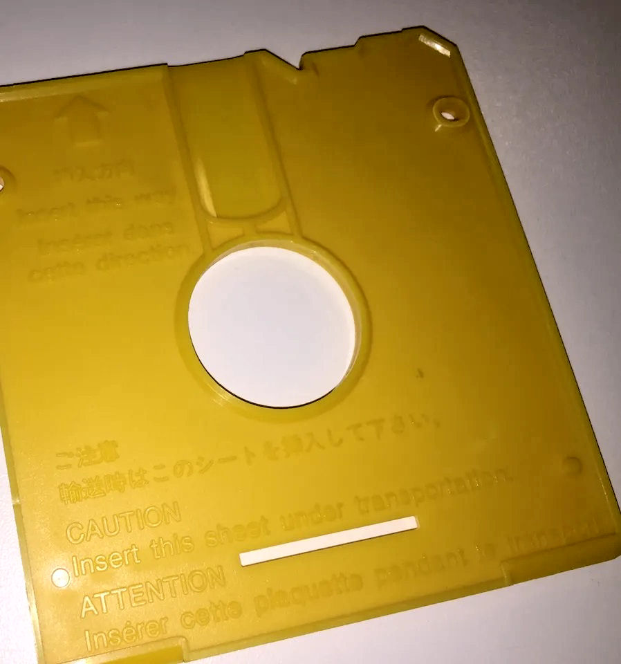
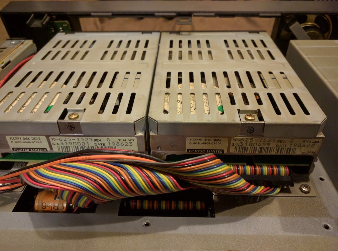
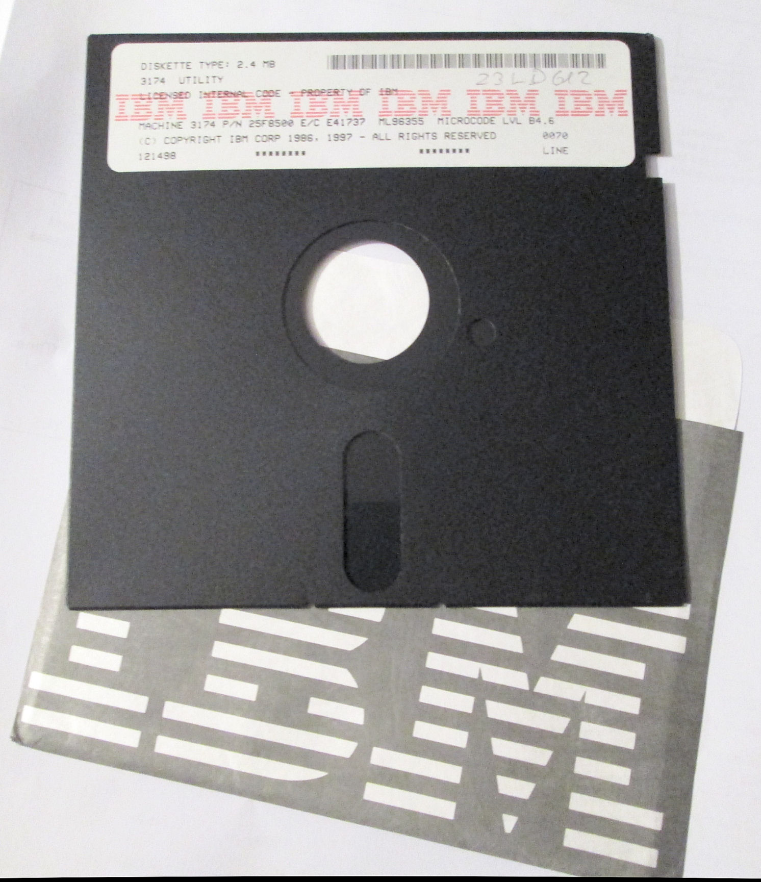
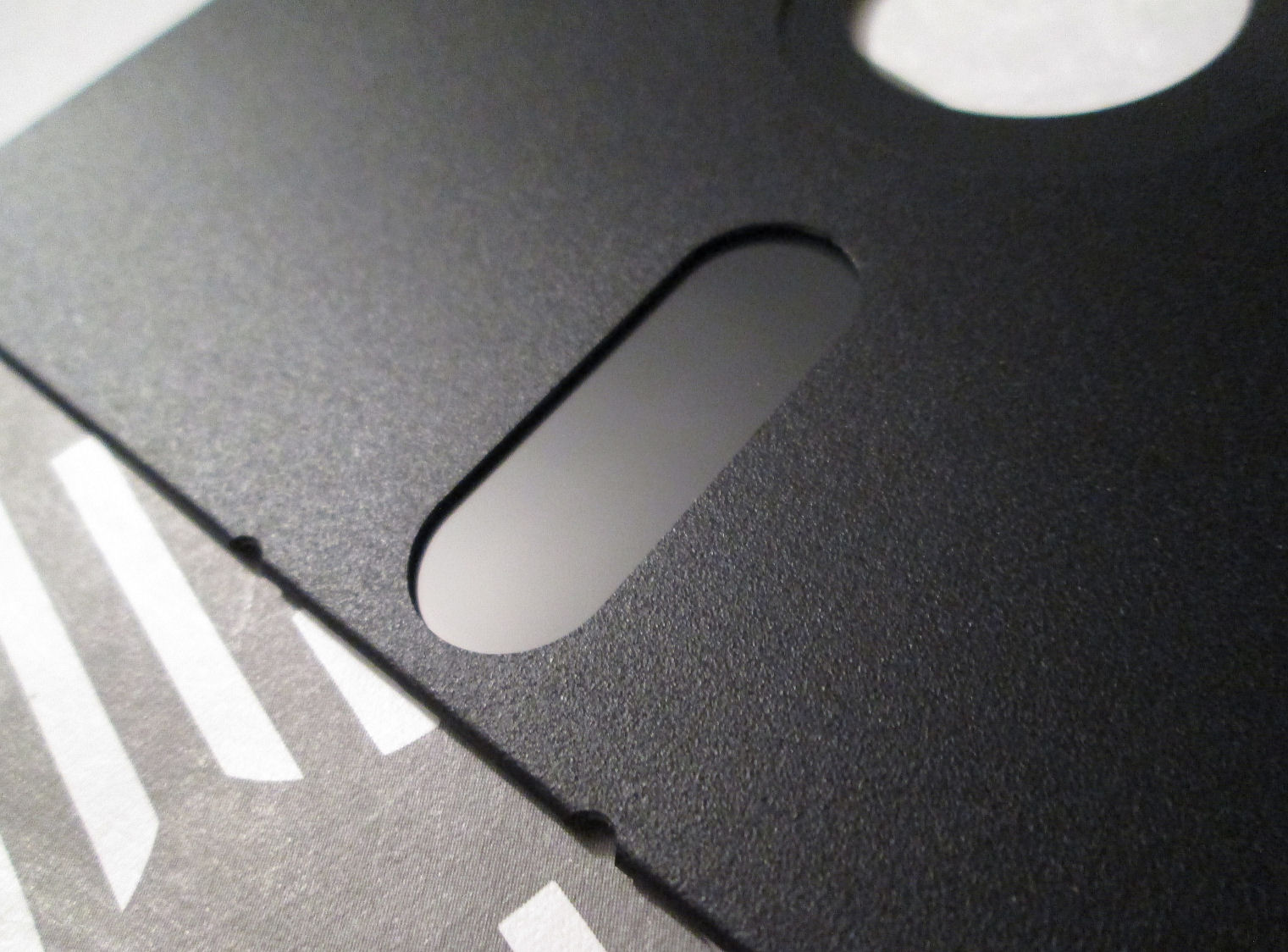
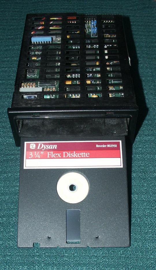
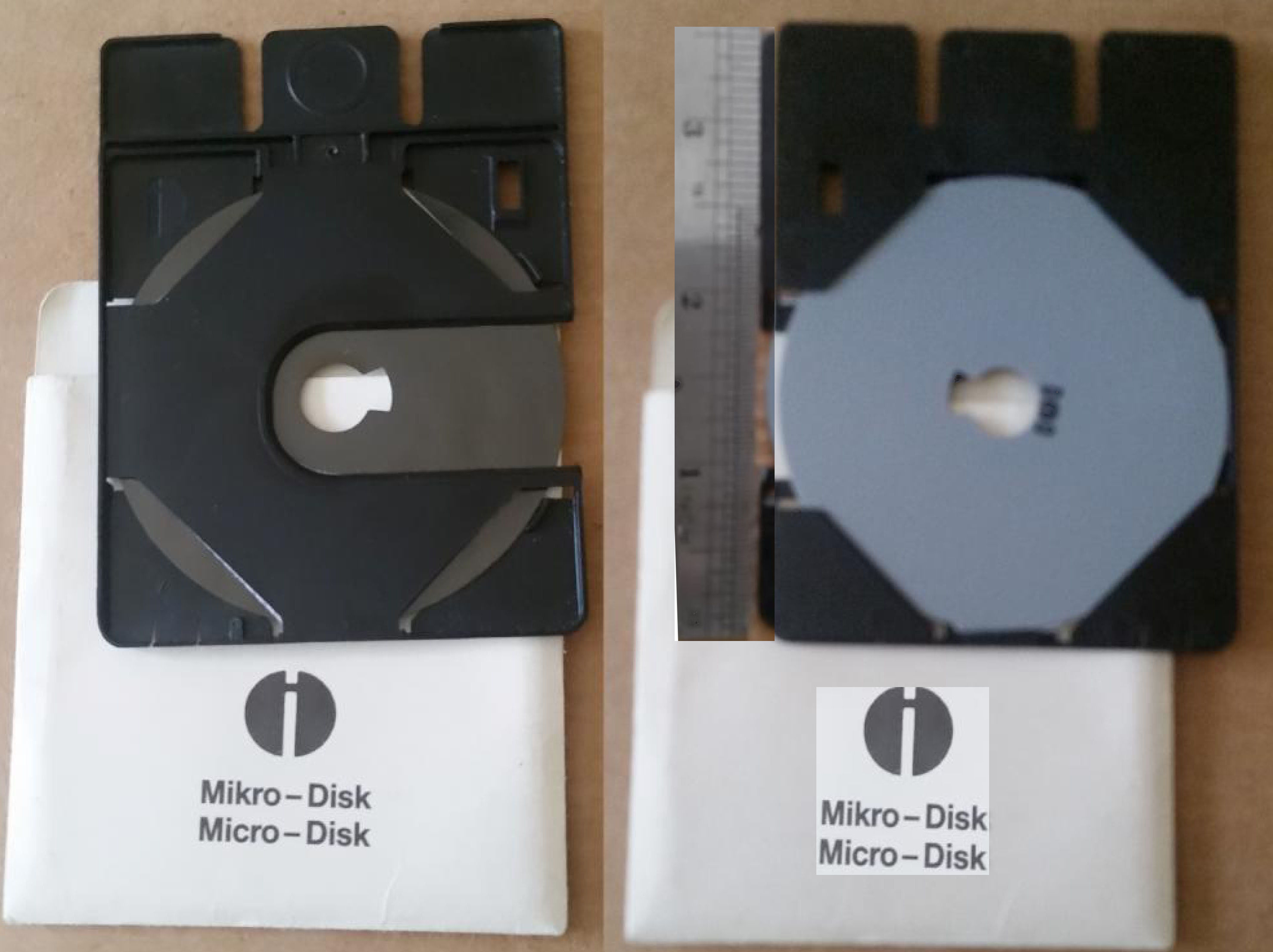
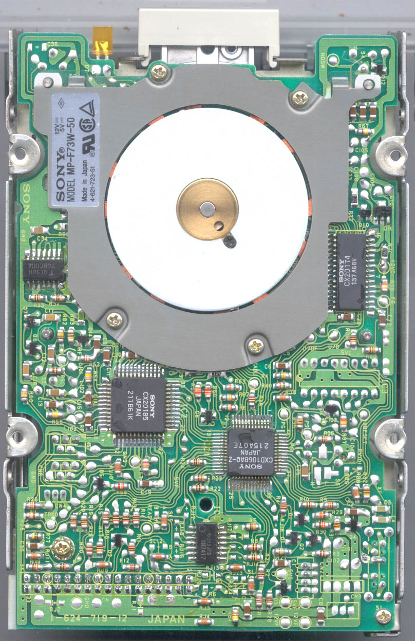