After the VCF-East April 2023 show, I acquired the Rev 9 Novasaur PC board from Alastair Hewitt. He exhibited the Novasaur and gave a talk about it. I was very excited to see a TTL computer with decent capabilities which also emulated a popular 8-bit microprocessor. Thus it could run vintage conventional software yet show 1980's TTL class microcontroller architecture; AND could be buildable and containable. He kindly offered me one of the boards on exhibit (a predecessor to the Rev 10 product), and later sold me some of the more difficult to find parts. Most parts were available at Mouser (distributor) or from common IC sellers.
In April 2025, Alstair Hewitt gave another Novasaur talk at VCF East 2025. I've updated this page with a Powerpoint of the talk with the text of the talk as notes.
I'm not directly affiliated with Alastair Hewitt or his company. Merely an enthusiastic customer.
Hackaday project
by Alastair Hewitt discusssions and posts ongoing.
Hewitt github site
Release 1.1 of code and ROM, candidateApr 2025
Production Candidate Release:
    Add XMODEM protocol for sending files via XFER
    Add ECC to Disk code - fix/detect disk errors
    Add System Lib - move/add library code
    Add 16-bit RAND, CRC, and Checksum instructions
    Reorg pages after removing interrupt support
Bug Fixes:
    Handle odd tx/rx buffer sizes
    Clear CPU command codes on warn start - fix reboot inconsistency
    Remove hardware interrupt support - not useful, too many race condition
Release 1.0 of code and ROM, productionJuly 2023
Different releases are found on github by clicking the "tag" or the "R1.0" icons.
Hewitt Web site for Novasaur sales. Quote from that page, Jan 2024: "Coming soon. Retro computer kits using just TTL chips to build full-feature personal computers. Learn more about the Novasaur on the official Hackaday.io project. Also available is a clone of the Gigatron with IO expander in the same form factor." The site was unavailable for a period after that. In July 2025 the site is not open but work is underway. Monitor the site for current status.
Presentations:
In April 2025, Alastair Hewitt gave a Novasaur talk at VCF East 2025. The link is to the VCF-East 2025 YouTube post of the talk. Topic was the startup operation of the microcode and descriptions of the paged and banked operation of the 8080 interpreter/instances and video display. This is based on the R1.1 code release. Here's the annotated PowerPoint slide show, text from the lecture is also in this document .
In April 2023, Alastair Hewitt gave a Novasaur presentation at VCF-East Apr 2023 This is an hour-long presentation of the Novasaur architecture. With the author's permission, here's an annotated version of the PowerPoint slide show. "Notes" are the edited text version of Alastair's talk. This is based on early codes probably pre R1.0.
"Dr. Dave" interviews Hewitt at VCF-Midwest 2023 This is a brief description by Alastair of the Novasaur and his Gigasaur (rework of the Gigatron TTL computer).
- Herb Johnson
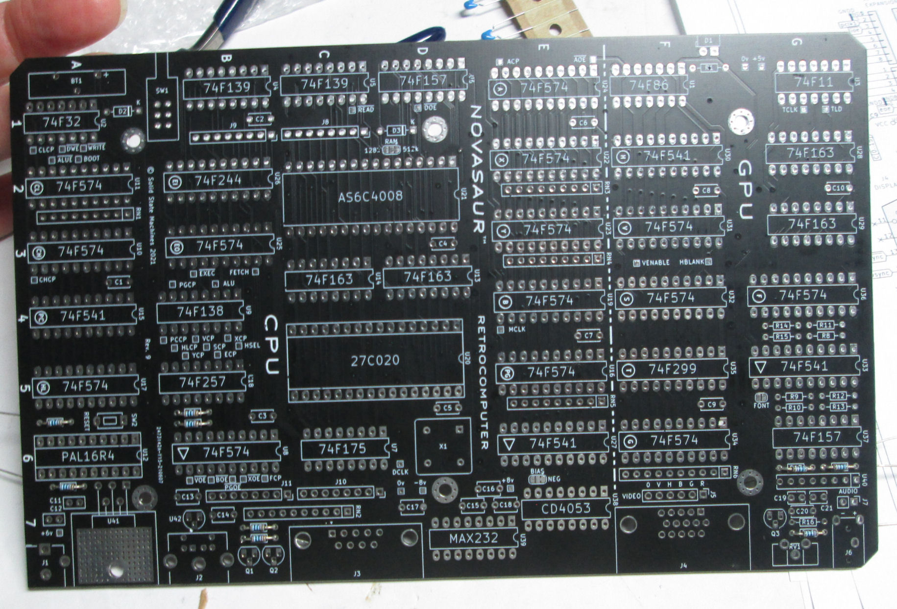
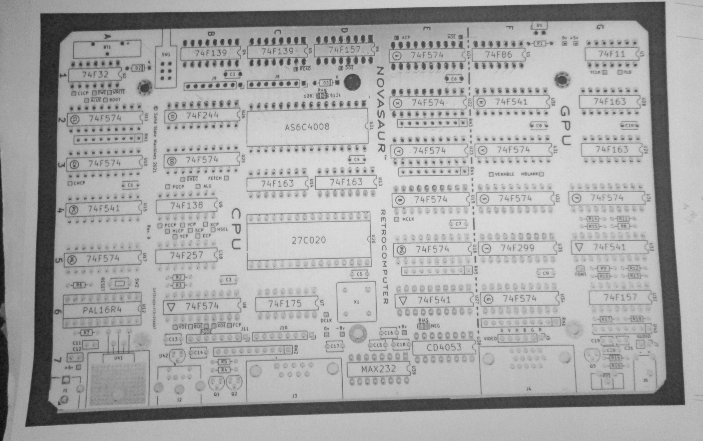
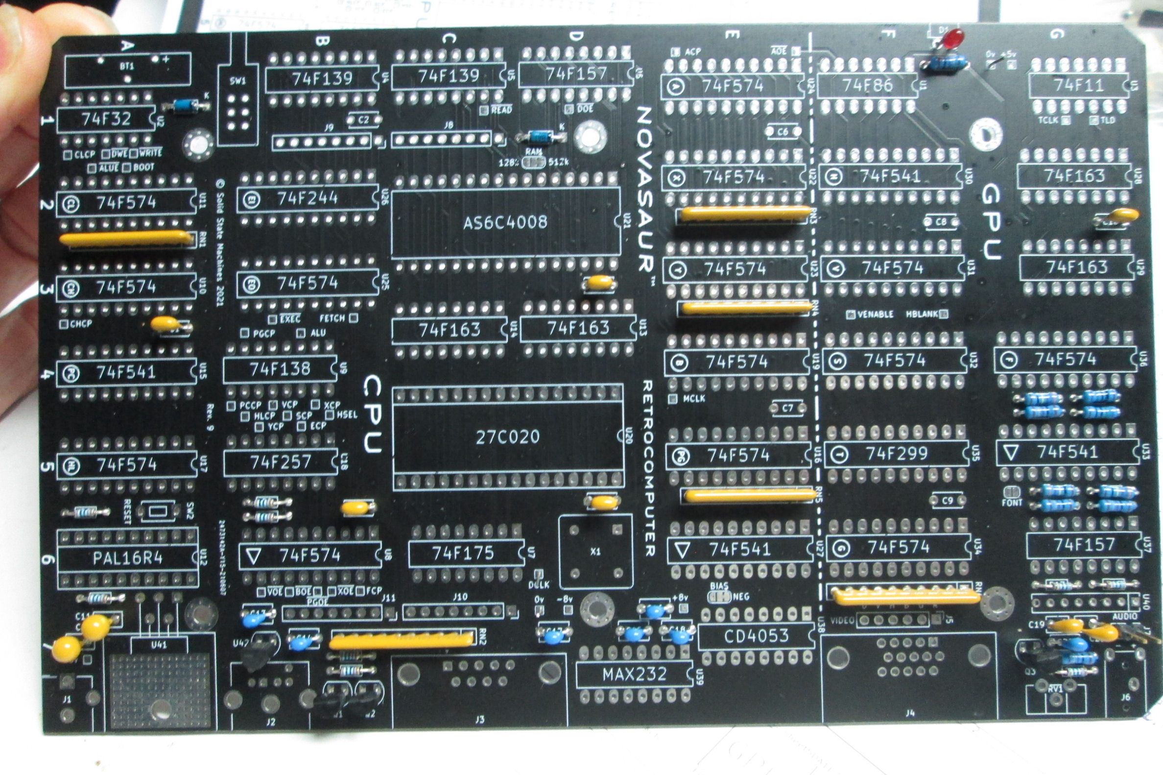
Empty Rev 9 board obtained April 2023.
negative image of silkscreen as assembly aid.
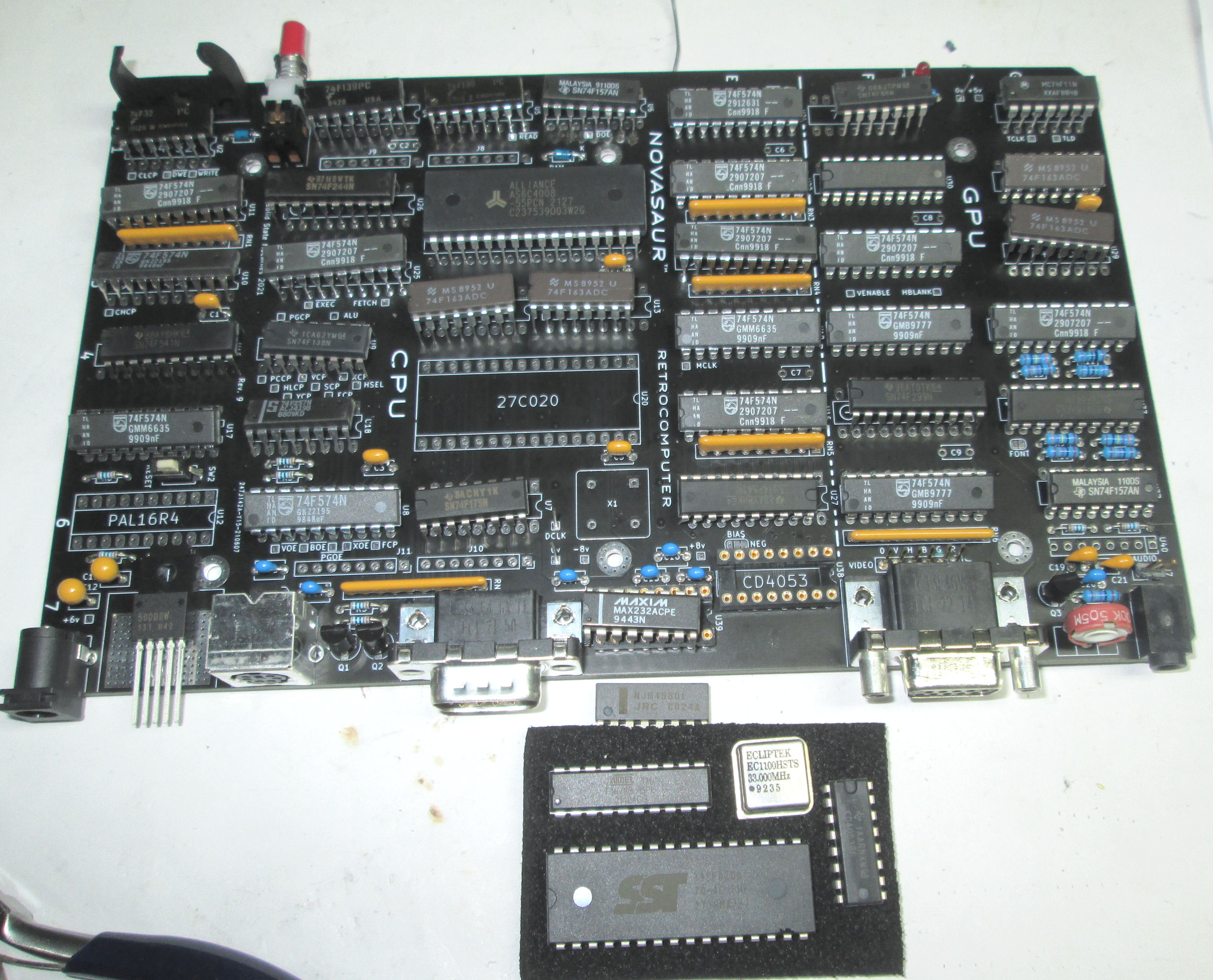
Chip placement on board to confirm parts count.
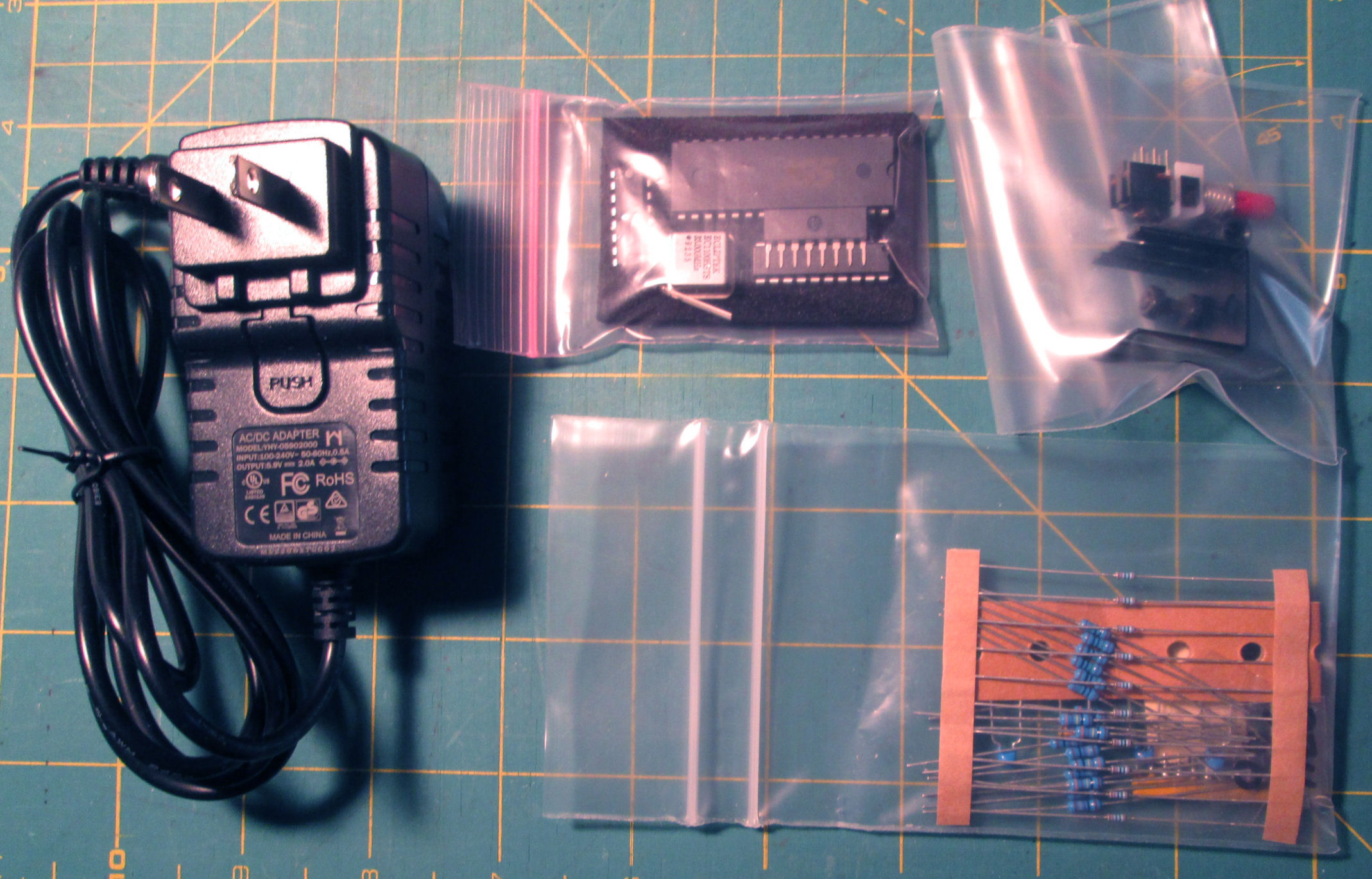
Unique mech and other parts, from developer.
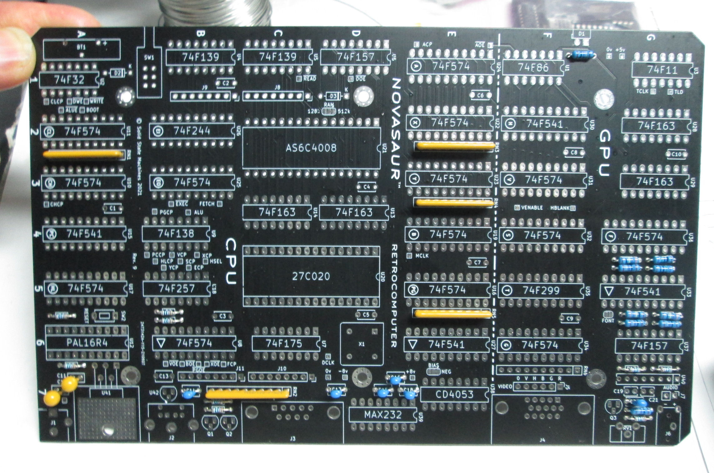
Install resistors, some caps.
Install caps
Install connectors
cut DIP to SIP socket for audio amp
Bend volt regulator pins.
Installed volt reg, heatsink, goop.
VGA diodes from V10 cobbled onto V9 board.
Sockets installed. Note 20-pin sockets have bypass caps.
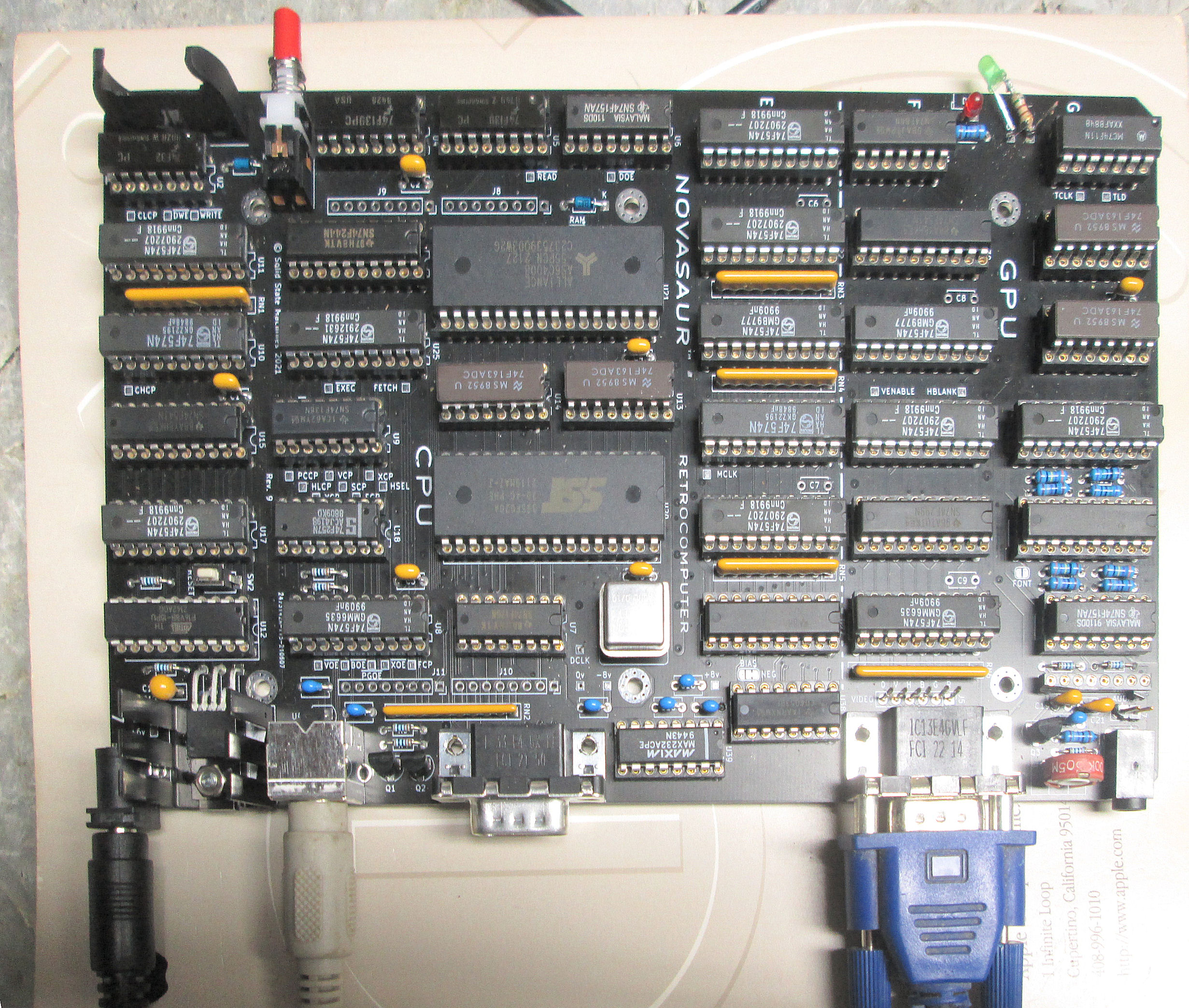
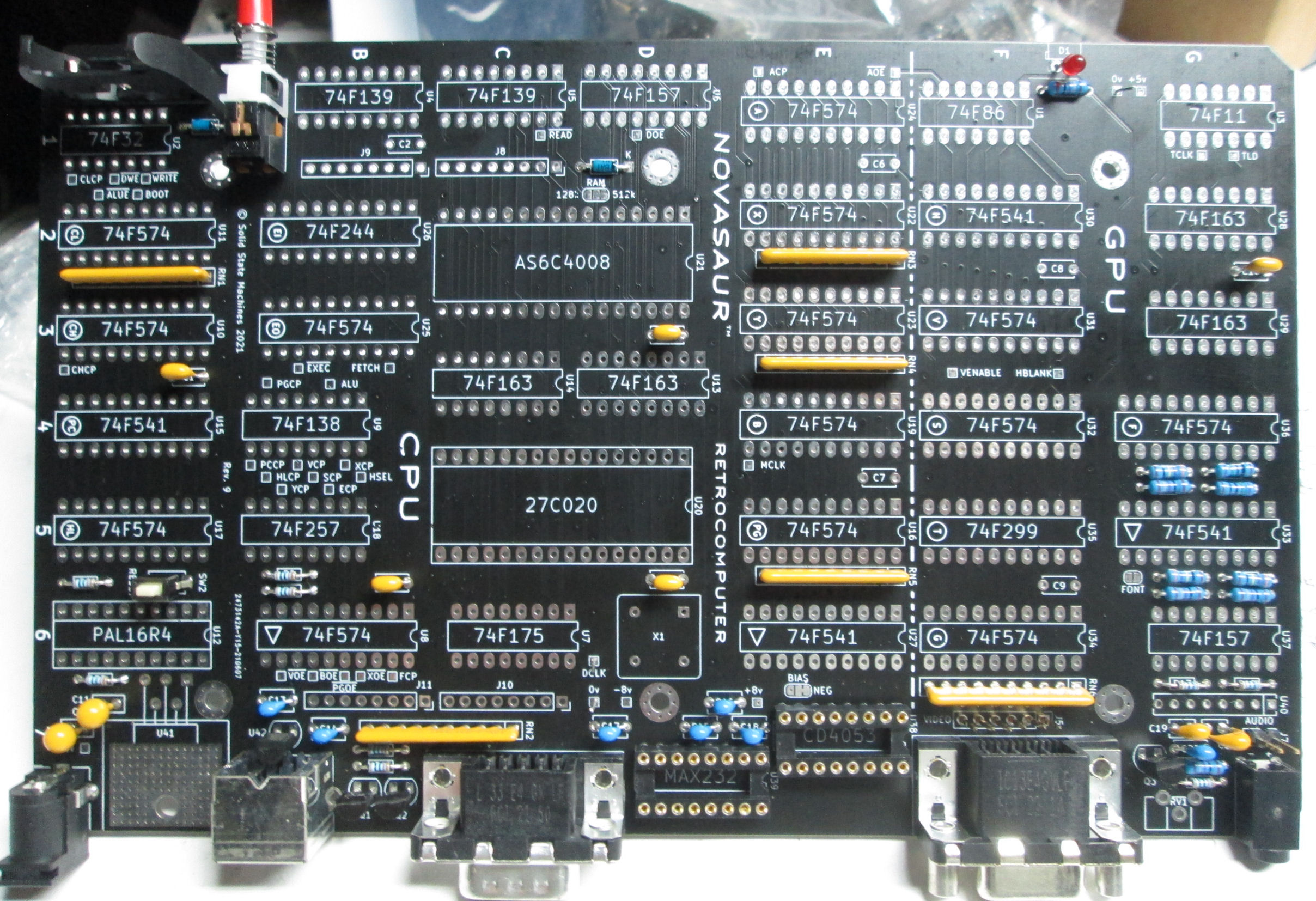
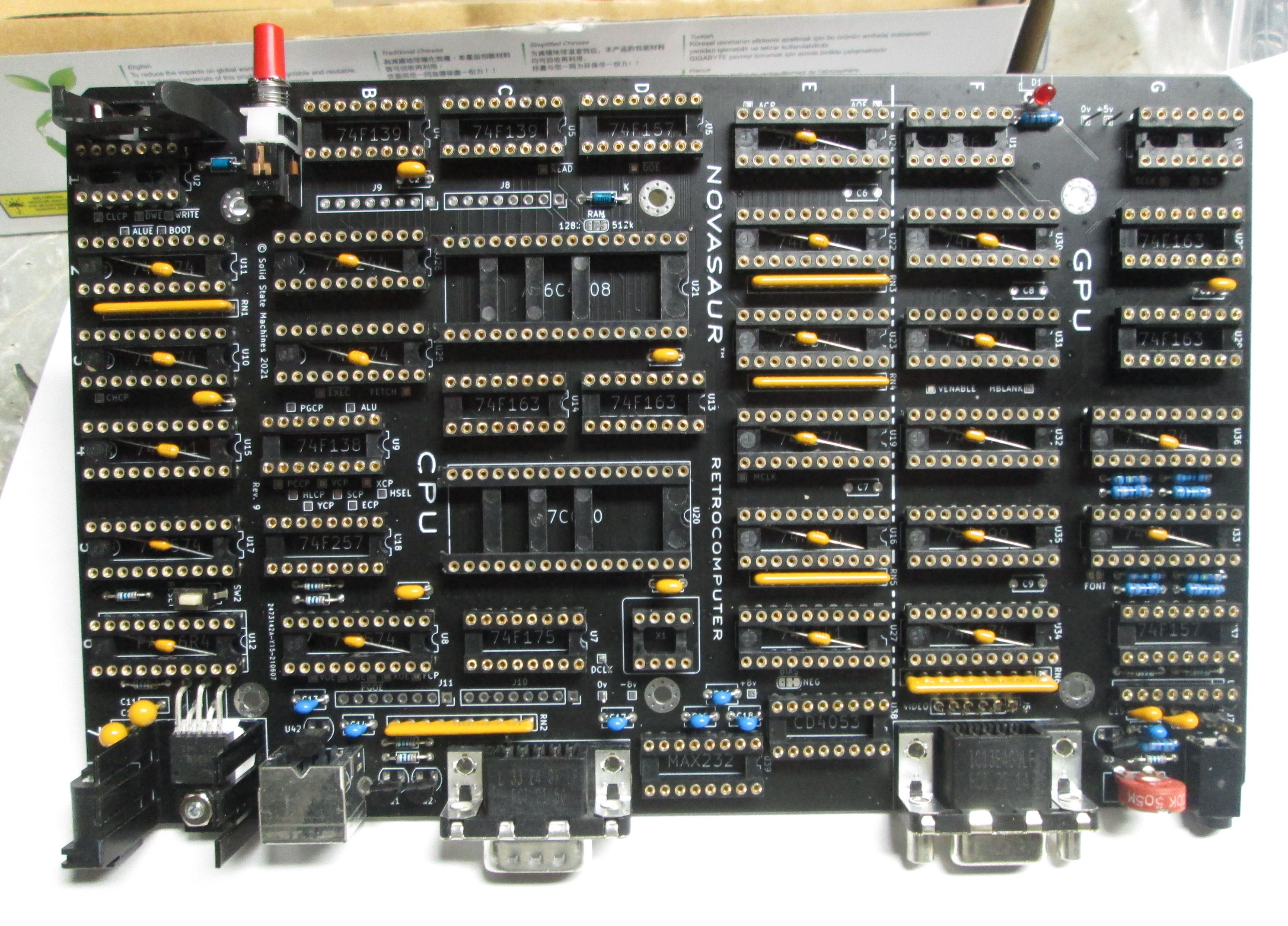
Assembled Rev 9 board, early Jan 2024
Note green LED and resistor across +5V/ground pins, power-on indicator.
Red LED is a "run" software indicator.
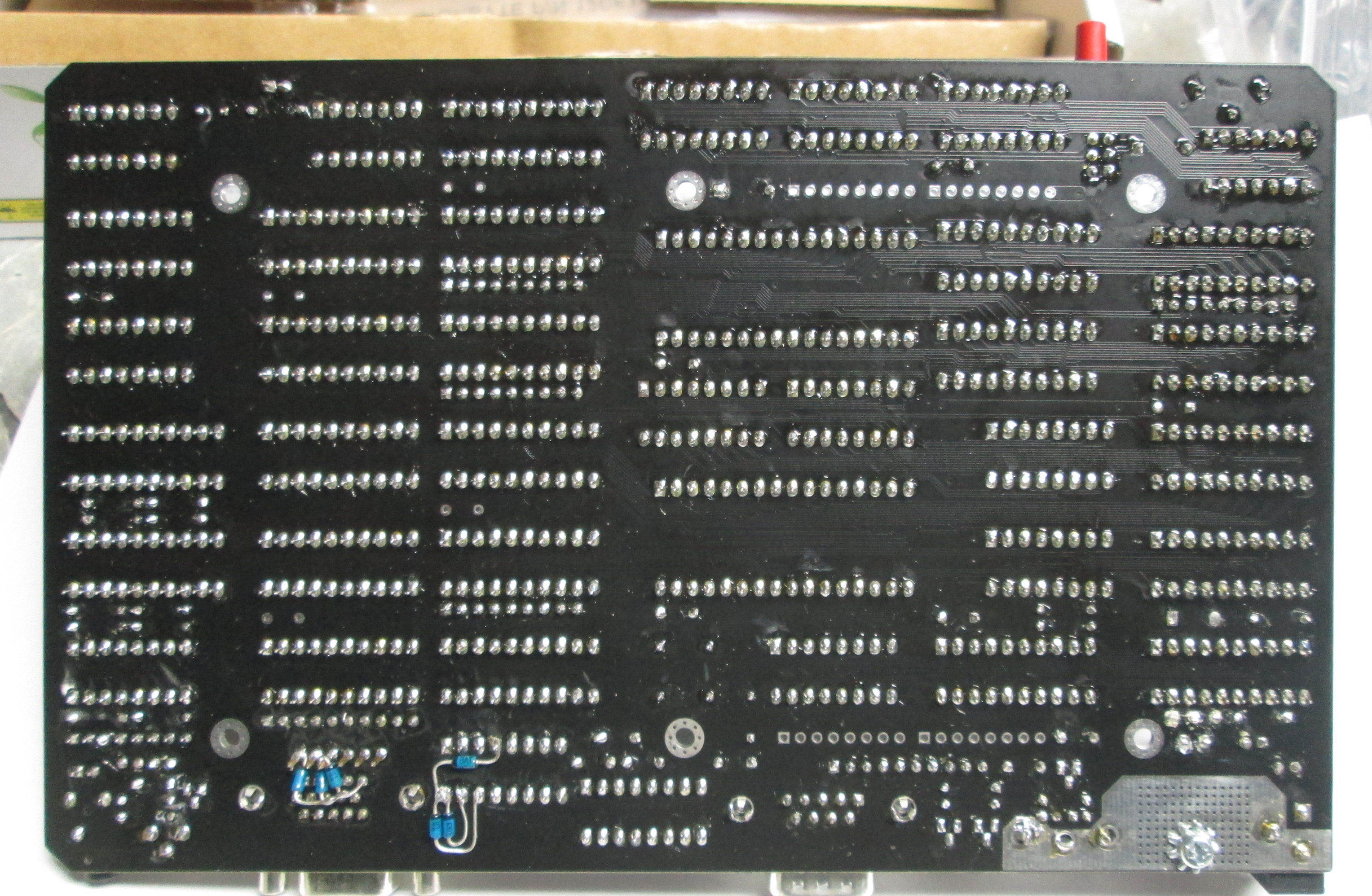
Back of assembled board.
Not shown: tested board with voltage regulator only, then added crystal osc.
Crystal IC inserted backwards. 5V regulator shut down! Seemed to survive at the time.
Then added a few TTL chips, looked at activity with scope, added more.
Board failed to operate with all ICs installed. Began diagnostics.
Removed U35, seemed to produce more stable operation. Board would run
for seconds, blink RED LED and LEDs on ps/2 keyboard, then stop.
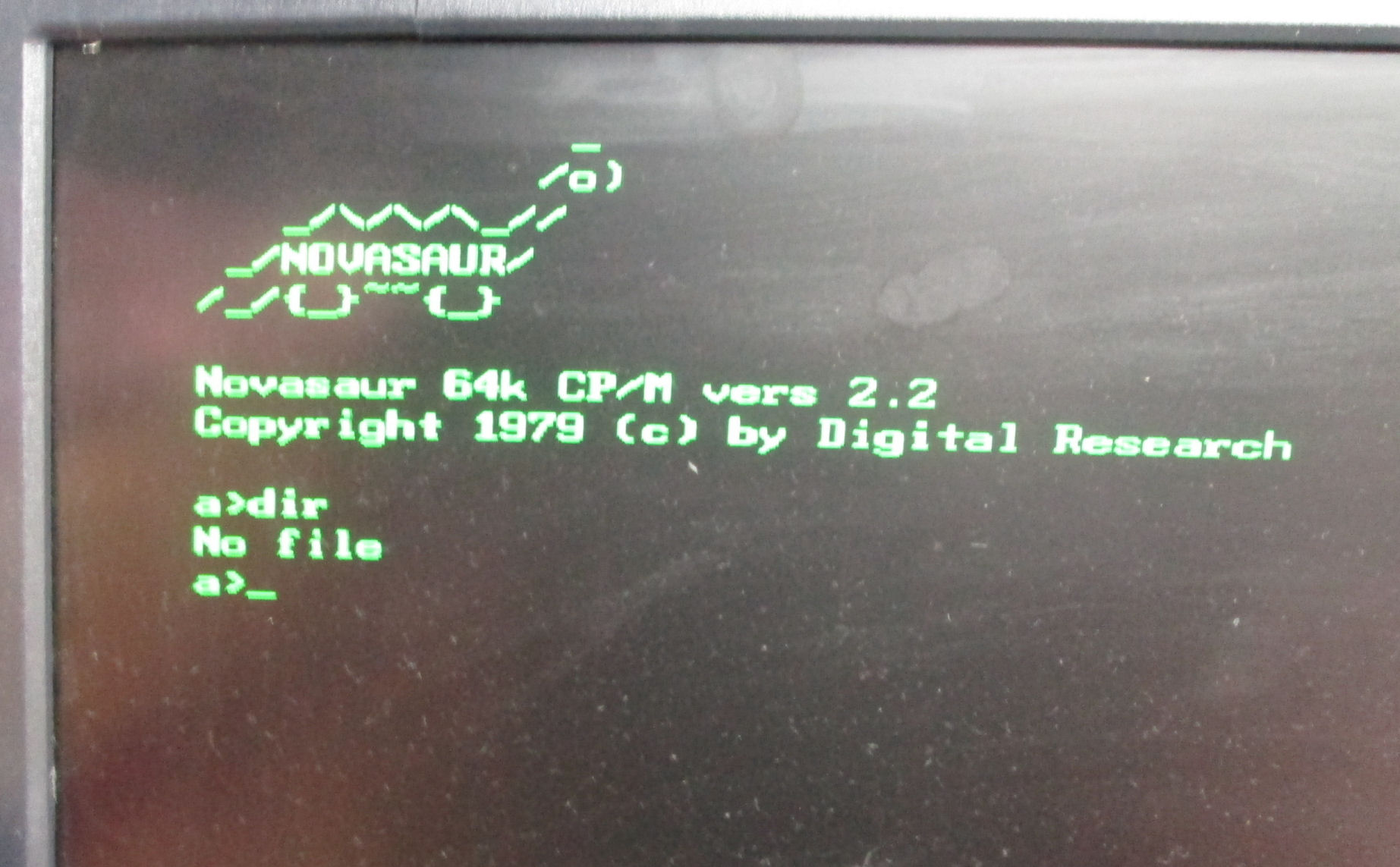
Jan 12 2024: While the Novasaur operated and ran the local programs, it would not retain a program/file copied into the battery-backed RAM disk a:. On "format a:" and "a:pip a:=b:/somefilename/ [vo]", a file would be copied. I could execute the file as a .com program too. But on power cycle, the a-drive contents went away. Why?
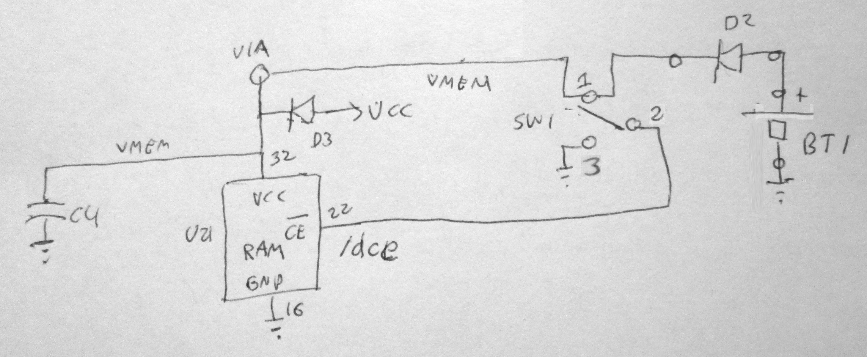
Days of correspondence with Alastair Hewitt later, we determined there was some power fault on RAM power (VMEM) that disabled or scrambled the RAM. Alastair recalled a problem between rev 9 and rev 10, where he added a series resistor to the SW1 circuit that produces the RAM standby signal /dce. Why? Some models of SW1 were "make before break". If you look at the VMEM and /dce circuit drawing, it shows the use of VMEM switched by SW1 to operate the /dce signal that when high (VMEM voltage) puts the RAM into standby. Whenh SW1 is switched to ground, the RAM is enabled and addressable. "Make before break" on my SW1, ended up grounding the VMEM line for a few milliseconds between SW1 pins 1 and 2. "Make" shorted the pins through pin 3; "Break" opened the pins, as the switch toggled from one pin to the other pin.
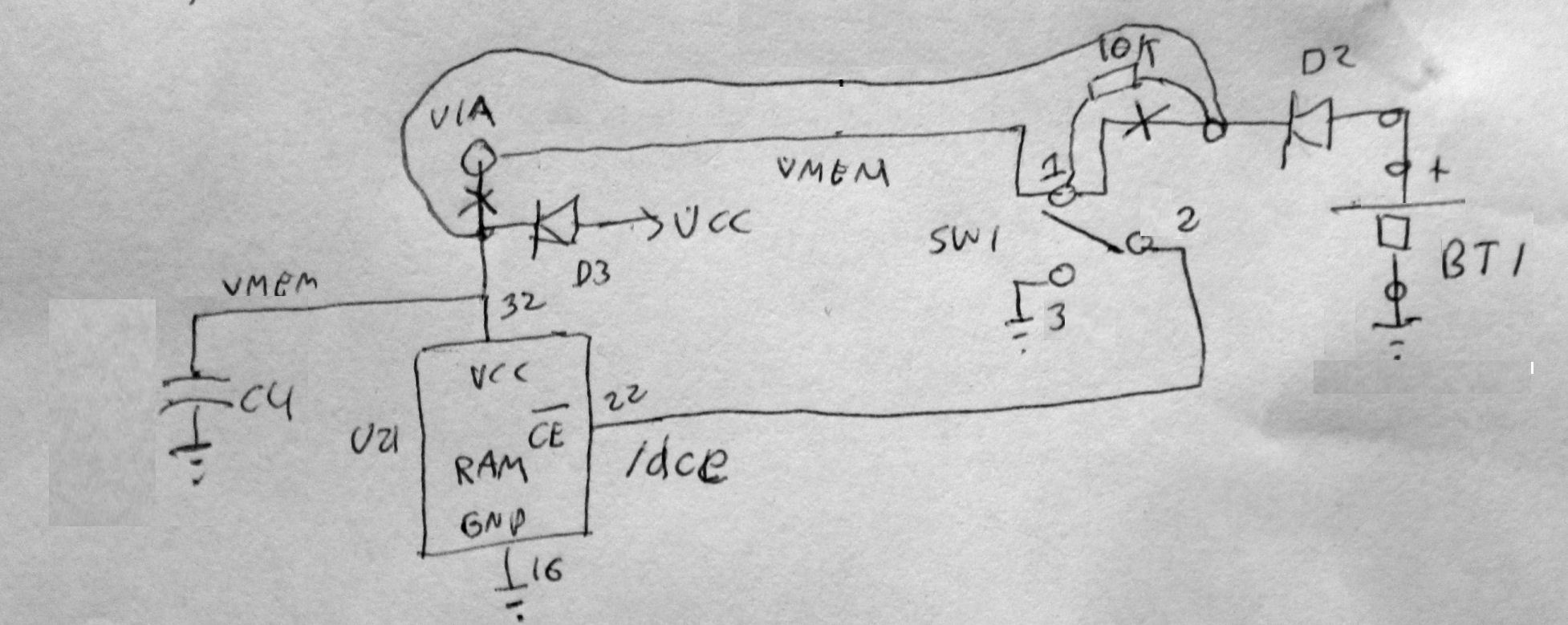
I verified this was thecase on my Rev 9 build. My oscilloscope showed the millisconds short by monitoring the Pin 1 diode junction to ground. Alastair didn't have this problem on his finaly prototypes, because he selected "break before make" switches on his builds, and on Rev 10 added a 10K resistor to the SW1 circuit from pin 3 to ground.
So what were my options? Swap out the switch would compromise the board. I could not add a series resistor at pin 3, as pins 3, 5 and 6 were on the ground plane. But: I could interrupt the VMEM line to SW1 pin 1 and put a 10K resistor there. That produces this schematic change. And so, Alastair and I discussed where to break the VMEM circuit. If you look at these two schematics, there's an X to indicate where we decided to cut the PC lines, as a matter of least damage.
10K ohms is a common pullup used by Alastair in the Novasaur. It's plenty of current for the /dce signal, but as momentarily shorted to ground by "make before break" SW1 it's only 5V/10K = 500 uA load momentarily on VMEM power.
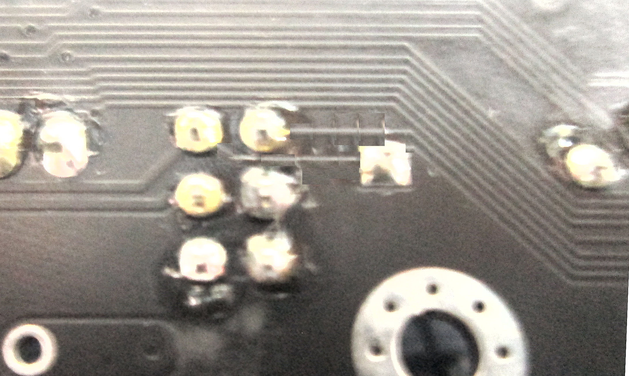
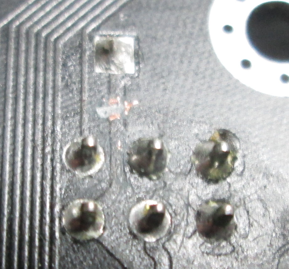
Look at the back of the board and component side of the board to orient your views of the repairs described below. I'm going to some trouble to describe this work, because it's work not often detailed. It's a useful skill, to determine and make these kinds of PC board changes on prototypes or after revisions.
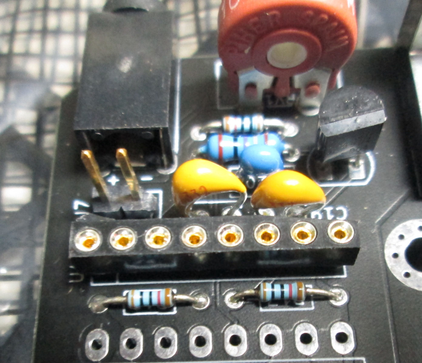
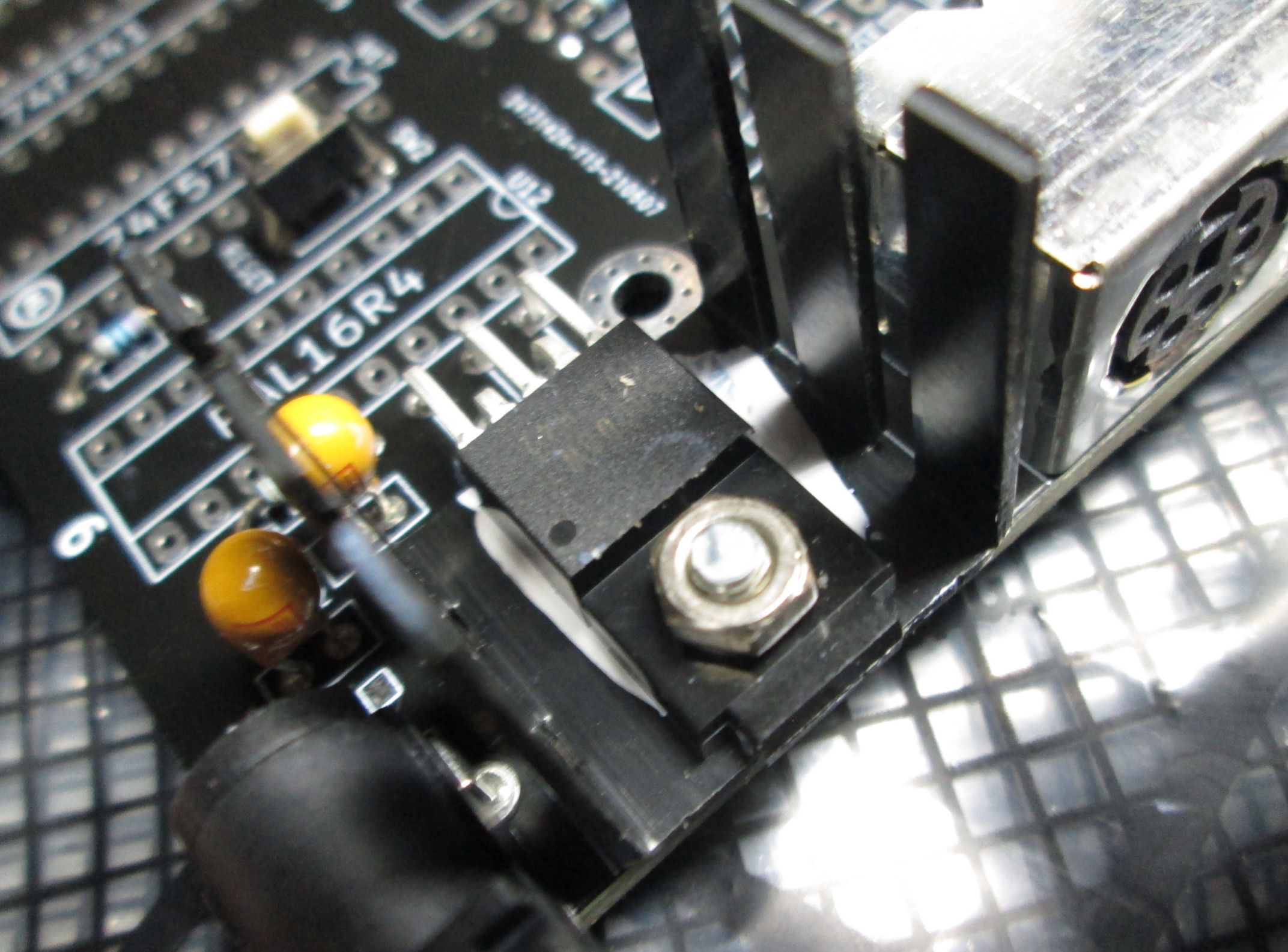
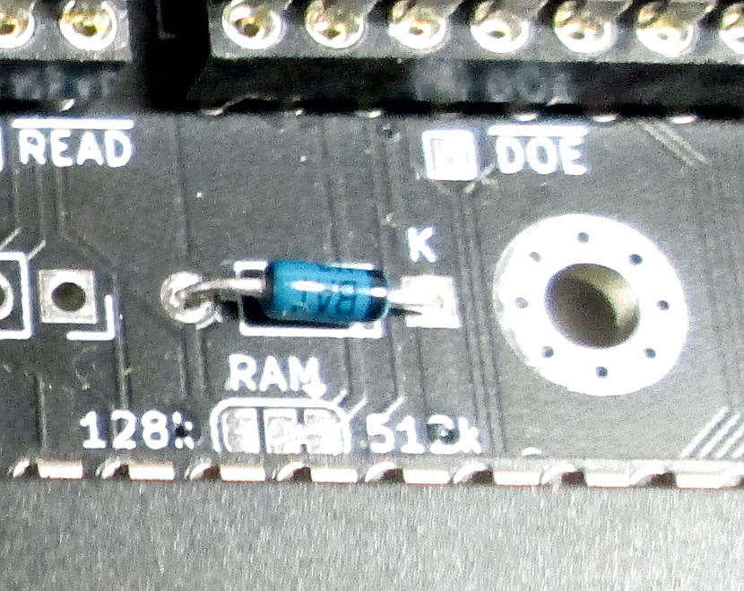
Why those physical points in the circuit? At the end near diode D3, there's a "via" or through-hole loop of copper. It's on a PC trace leading to D3. [The trace is along the "K" mark in the photo, the diode to the left.} Cutting the trace after the via would disconnect the trace from there to SW1 pin 1.
At the trace between SW1 and diode D3 [SW1 pin 1 is upper left of the six pins; diode is the rectangular hole to the right] cutting the trace there completes disconnecting VMEM from SW1.
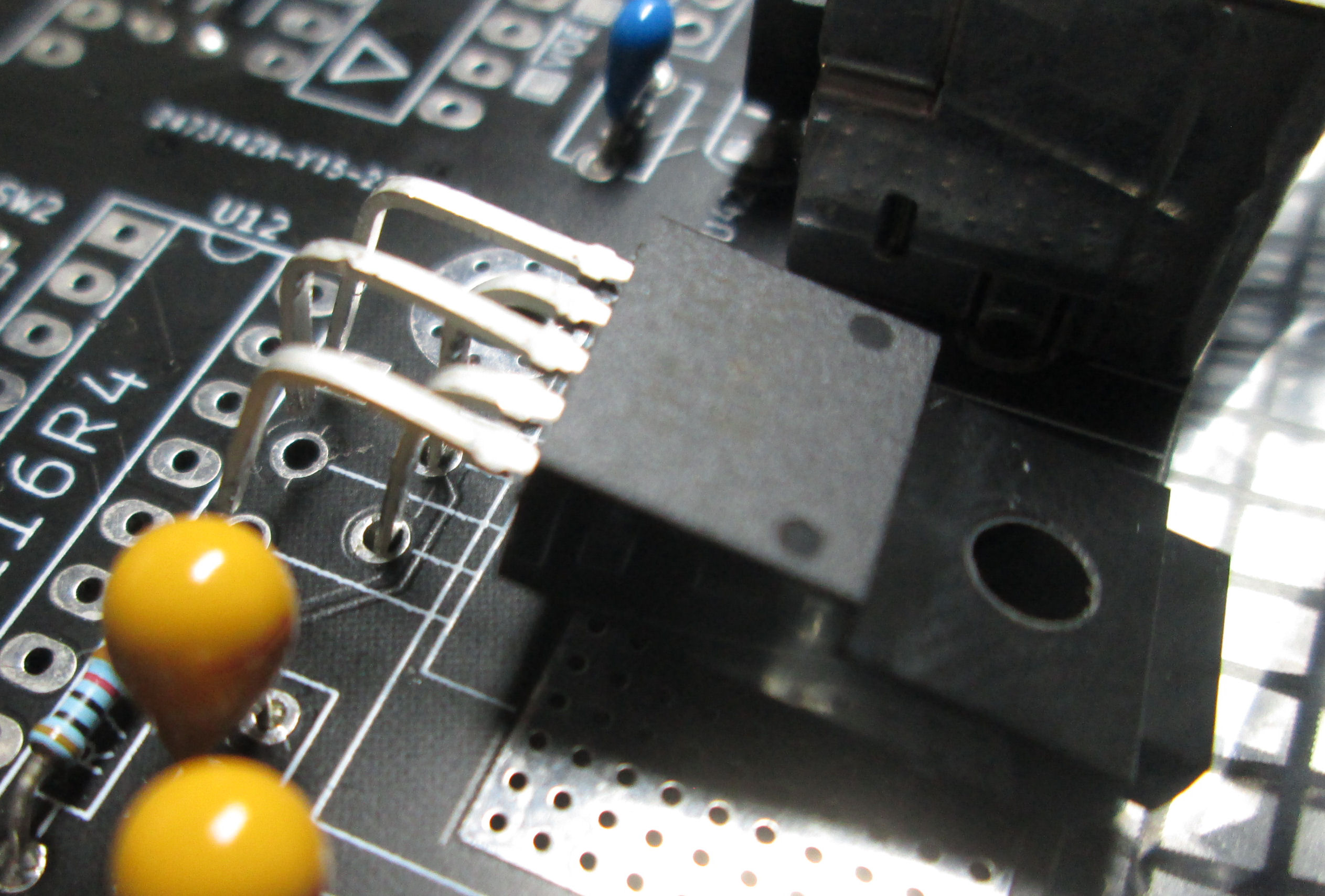
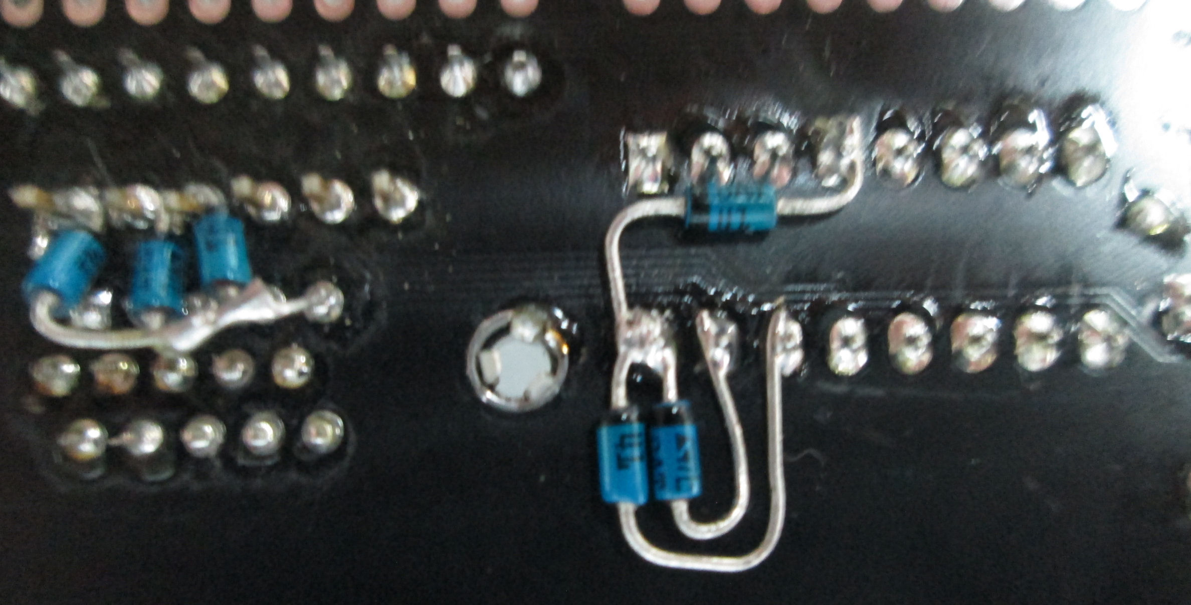
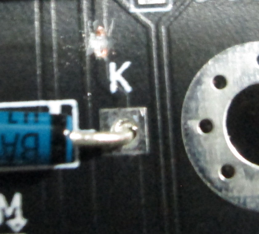
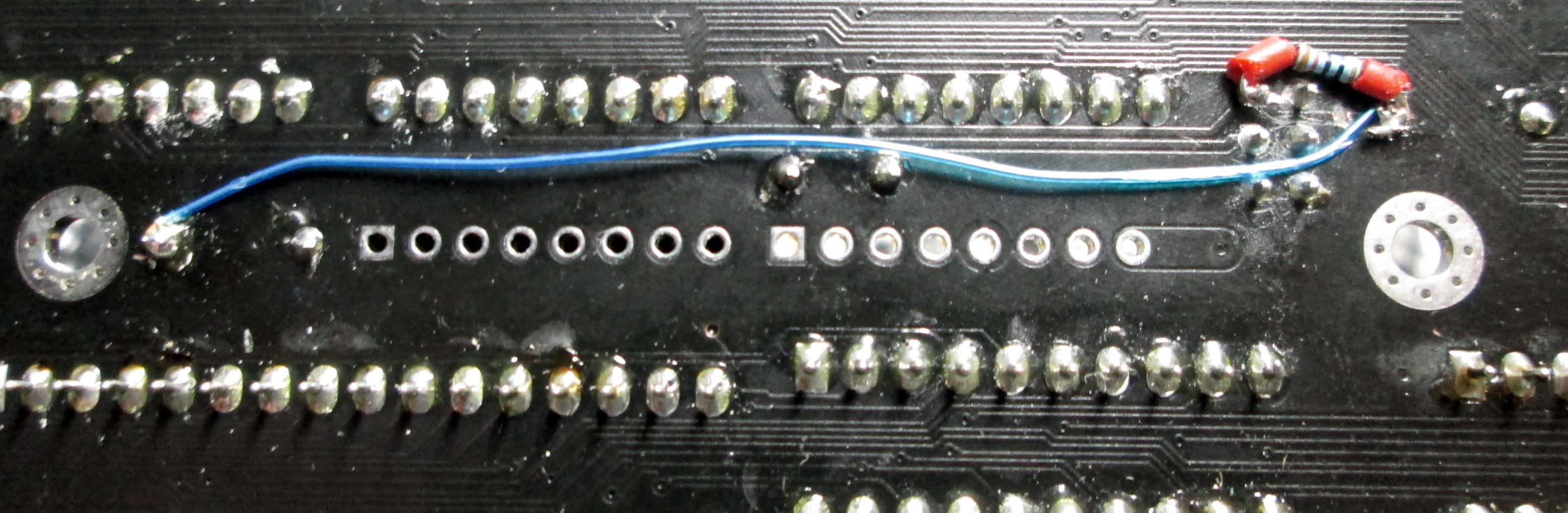
The two points at D3 and D2, can be reconnected with a soldered wire between the diodes leads (convenient to solder). Then, a 10K resistor can be soldered from D3 to SW1 (shown in the wire photo) to provide a pull-up voltage for the /dce signal. Look at the back of the board before the fix to orient your view.
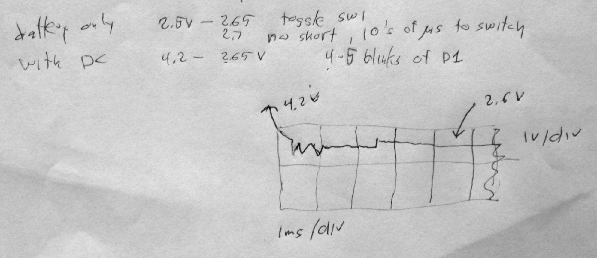
Results? The VMEM ground pulse was removed! The pulse only occurs during the milliseconds of SW1 "make before break" so my non-storage oscilloscope could not retain an image of the almost-removed pulse. in this sketch of the oscope trace, there's a few milliseconds where VMEM is bouncy or dips for a few tenths of volts. Again, that's the 10K additional load in effect. As long as VMEM is above about 1.5 volts, the RAM will retain its contents during the /dce (standby) signal. My notes show, VMEM is 2.65V under a depleted coincell battery (with a diode drop from sub-3.0V), 4.2V under CD power (.7 diode drop from 5.0V). The 2.5ms pulsed drop of a few tenths, is the 10K resistor load, as SW1 bounces around.
Testing the software after the fix, showed the A: RAM drive retained the DDT.COM program after power cycling and DC power removal, at least for minutes. Procedure for the corrupted RAM was to "format a:", followed by "pip a:=b:ddt.com[vo]", then running the DDT program from the A: drive. Then of course, to power cycle and run the program again. Not quite a binary test of the RAM but enough to suggest the RAMdisk was operational. A CP/M CRC program, is one way people confirmed that disk contents were uncorrupted; I'll serial upload that program to test the serial transfer utilities at a later time.
Jan 2024: initial serial problems. See my serial notes below. These issues were either errors on my part, or issues Alastair resolved. The process was informative to both of us. There's Nvasaur details here not available elsewhere (at the times published here).
In Jan-Feb 2024, Alastair responded to my confusion about operation of XFER serial file transfer before and after we resolved my broken RST serial hardware-handshake signal. Alastair decided to work on an XMODEM transfer program.
Feb 2024: Along the way, because of lost RAM disk memory bits during power cycling, Alastair implemented an ECC correction method.It will become available in his next ROM revision 1.1.
In March 2024, I reviewed Alstair's VCF-East presentation on YouTube, said video courtesy of VCF Inc. I edited the speech-to-text narration into text, which I added to my copy of the PowerPoint from Alstair's site. My annotated PowerPoint copy is above on this Web page. - Herb
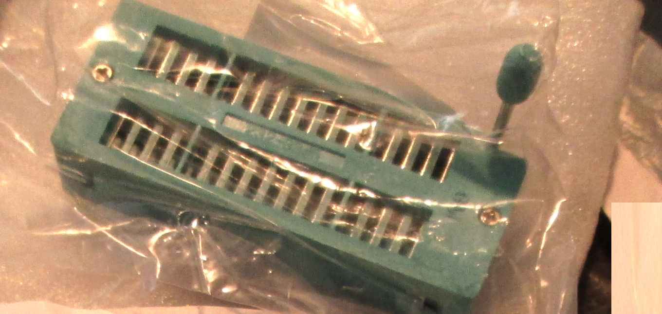
Apr 2024: ZIF 32 socket adapter for Flash ROM. see my notes below. A ZIF socket makes it easier to run various ROMmed binary images. A ZIF socket is not part of the intended Novasaur parts list. - Herb
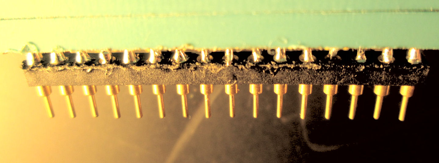
In Apr 2024, I constructed a ZIF32 socket adapter, to facilitate swapping the flash ROM of the Novasaur. Most ZIF sockets have *rectangular* pins which are wider than standard DIP socket pins. So ZIP sockets won't fit the Novasaur PC board. The work around is to solder the ZIF socket to a machine-pin socket, but that's mechanically difficult. Here's what I mean.
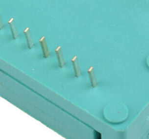
The ZIF 32-pin socket as purchased looks like this in the bag as sold to me. Several dollars buys one on eBay, Amazon, etc. But the pins at the solder-end are too big. They are rectangular, extensions of the rectangular pins of the ZIF socket which open and close.
The hack, is to solder onto those 32 pins, a machine-pin socket, which of course fits the PC holes for the Novasaur flash-ROM. This is a difficult solder, because the rectangular ZIF pins won't hold in the machine-pin socket. An additional difficulty, is that to heat the pins during soldering, it's easy to distort the thin plastic 32-pin machine socket.
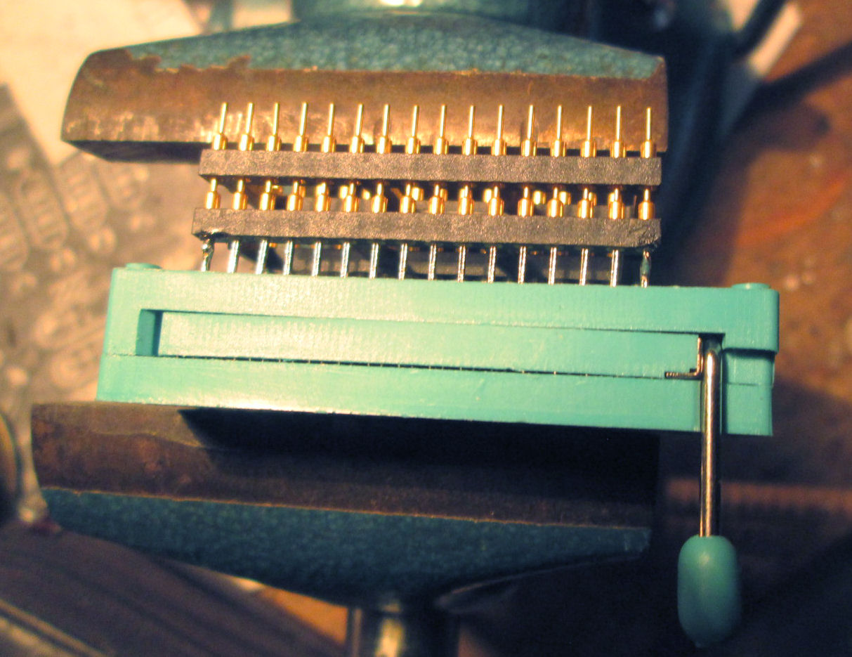
To resolve these problems, 1) I put the ZIF and DIP machine-pin assembly into a vice to hold them together; and 2) I added a second DIP machine-pin after the first, to anchor the individual pins of the soldered socket. Plus, the second pins provide a heat-sink of sorts.
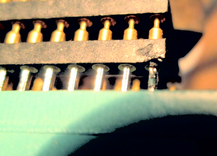
Here's the stacked ZIF/DIP/DIP assembly in the vise. My first move, was to solder the four corner pins. That serves to anchor the ZIF and DIP sockets. If you look at this close-up photo, (the lower row of pins and sockets) you'll see the ZIF pins sitting in the "cup" of the DIP socket pins. Observe the rough solder on the corner pin, the damage to the DIP socket from the relatively blunt soldering tip. This is hard to photograph; it's hard to light and see as well.
Here's one side of the soldered ZIF/DIP socket assembly. You can see, the solder doesn't fill the cup of the DIP socket. I simply can't heat the DIP socket pins except at the junction of the ZIP rectangular pin. The ZIF pins themselves are some kind of steel, not copper or bronze like the DIP socket pins. Nonetheless, I made an effort to inspect and correct the 32 pins, to avoid a "dry socket" connection that would fail days or years later. - Herb
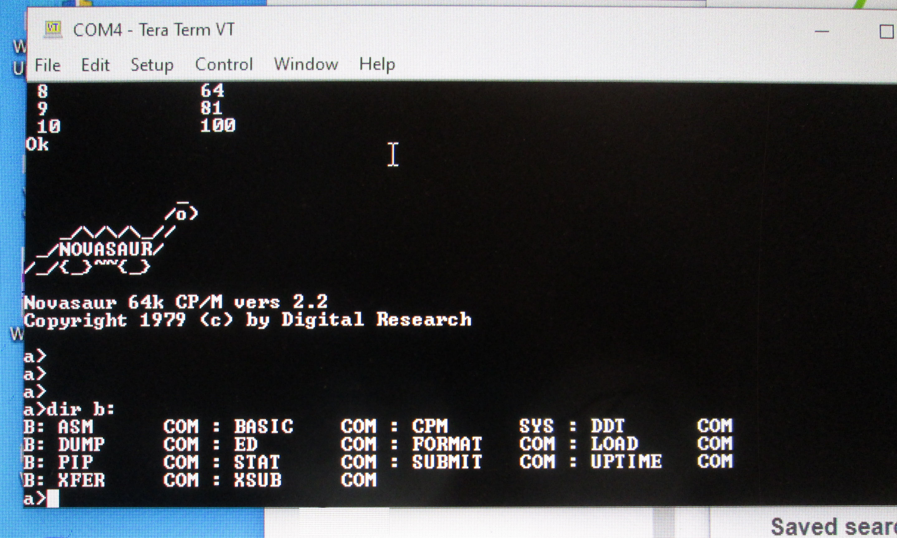
Jan 23-26 2024 summary: I connected the Novasaur serial port to a PCI-1X serial port card on a Win 10/64bit computer. I ran the Novasaur 8080 CP/M successfully as designed, under TeraTerm. The serial spec is 9600 baud 8 bit no parity 1 stop bit. I wasn't sure initially about handshaking, that usually depends on the application. The XFER file program with the Novasaur, depended on RTS handshaking to recieve without overflowing various serial receive buffers. I had a problem with use of RTS by TeraTerm; and so small files sent from TeraTerm/Windows to the Novasaur CP/M were incomplete.
It took some days, different monitoring, my review of the 8080 recieving code, and technical discussions with Alastair, to resolve how the Novasaur was operating. By using different monitoring tools, I found the failure point for the RTS signal from Novasaur to TeraTerm. Once RTS was recieved correctly by the Win10 application, recieved files were transferred successfully. Along the way, I learned something from Alastair about Novasaur serial and microcode operation.
After these experiences and discussion between myself and Alastair, he updated 8080 support to include XMODEM transfer protocols. Some microcode changes were needed to improve performance. These were incorporated into the V1.1 "release candidate" for the microcode and 8080-coded ROM. - Herb
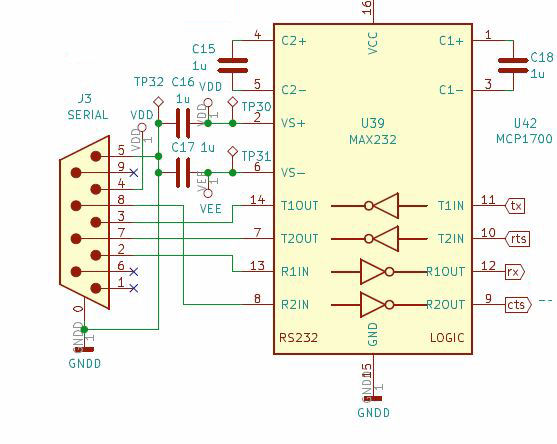
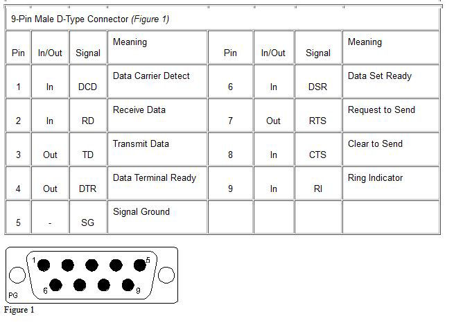
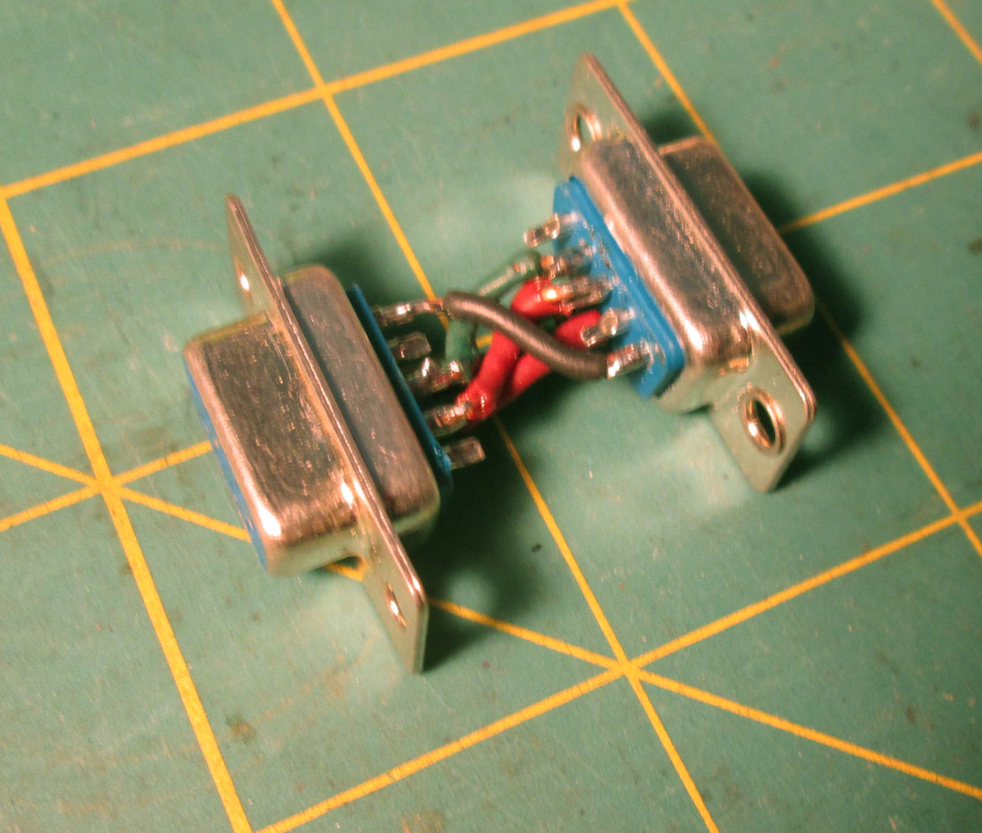
On schematic review, the Novasaur hardware supports RTS/CTS signals through a MAX232 chip to DB9 connector. Pinouts of the "IBM PC serial" are in this image. Both use male DB9 connectors. So the Novasaur serial port matches the IBM PC port. So to connect the two, a pin 2-3 "twist" is needed to mate RX with TX, and an 8-7 twist for CTS with RTS. Pin 5 is ground for both. Other pins are not in use.
On my desktop PC, I normally use a male/female DB9 "straight" cable, to attach to legacy serial devices. I had to scrounge but I found a female/female cable, luckily "twisted". And it worked! Later I constructed and added a DB9 "twist" or "null modem" adapter, again added to my straight-thru cable.
Brief tests of the CP/M XFER program had mixed success. Of course I got the CP/M boot and prompt on TeraTerm's display. I used TeraTerm's "send file" feature with its serial setup of "no handshaking". XFER is a CP/M 8080 program from Alastair, apparently a no-handshake character transfer (I have to read the source). I was able to transfer an ASM source text file, which looked plausible on inspection. Transfer of a .COM program failed, even under TeraTerm's "binary" send. DUMP inspection on the CP/M side, showed the first bytes were correct, until a few bytes just before the 256th byte. Also, the file transferred was too short by tens of bytes, but included the last tens of bytes. Documents about the Novasaur suggested the serial firmware implemenation uses a 256 byte buffer of some sort.
For further testing, I added a serial LED monitor dongle to the serial cable. And i tried to diagnose, the RTS signal and why the file "skipped" a block or so of the transferred program file (a file CRC checking program). But it was not until I used an oscilloscope to look at the RTS signal, that I determined that the LED dongle was at fault for not sending through the RTS signal to the PC. With the dongle removed, XFER worked correctly and the CRC program was received repeatedly.
Following below, are descriptions of XFER and the Novasaur's serial operations in hardware and firmware. They provide a deeper look into the Novasaur and that's a useful way to become familiar with its implementations.
So I'm transferring a small 8080 CP/M program called CRC, which computes a CRC32 checksum of a file named. here's the ASM source and the assembled listing and finally the .com file renamed .bin for convenience Don't run it on Windows, it's an 8080 CP/M program of course. The program starts at 0100h and ends at 035CH; note that is 25CH bytes, which is two pages (256 bytes) of code and a fractional page. The examination tool I have for files on the Novasaur CP/M, is DUMP, a file hex dump program.
When I attempted to "receive" the crc3.bin binary from Win10 to the Novasaur, with the XFER /R program, I got two general kinds of results over about a dozen plus tries. Either I got a file of bytes 0000H to 017FH, or I got a file of bytes from 0000H to 027FH. So that's two, or three, 256-byte "pages; the actual .com file size is about 0257H bytes.
The larger-sized file was correct because 1) it's the right size 2) it executes and produces a consistent result, a checksum for a named file. If I checksum itself, and other copies transferred that produced a file of the same size, those too have the same checkum, which happens to be CRC = E7 99. (If you try to replicate this result, read further about how XFER "fills" the recieved file to the end of the file block.)
Here's some cryptic notes about running that CRC program. I varied how long to keep XFER waiting before starting the file-transfer from the Windows system (30 seconds is maximum). In ten or so transfers, only three completed with a full sized (and functional) file for CRC.COM.
The files too-short were of size 0180H (0000 to 017FH). In general, the codes in the transfered CRC.COM, matched the original on my Win10 box, until some point past the first 100H bytes, but at different places in the file each run.. Then the file contains, the last several tens of bytes of the end of the original CRC.COM; followed by fills of 1AH's to the end of the block at 017FH. In effect, the file "skips" a bunch of bytes, as if they were sent by Win10 but not recieved by XFER.
At what point does the "skip" occur? I made some careful checks of several runs, but they varied in the number of bytes skipped. But all contained the last bytes of the transferred file. WHen i tallied up byte addresses for the "lost data", I go these number: 0129/022AH, 0141/0242H, 0156/0057H, 0111/0212H. So I saw, that a whole 100H buffer (256 bytes) seemed to be "lost" in the middle, but in different places. Interesting ....
But now I'll go back in time, for my review of the 8080 code side, which I did after gathering the information above.
Looking at an assembled XFER.LST. the command switches are /R to receive and /S to send (at the Novasaur). The recieve option, opens a named file. It loops to read serial with RECV_LOOP calling RECV, and fills a 128 byte buffer (at address 0080H to 00FFH), then write buffer to (RAM)disk, This is repeated until no more characters are received, then the last buffer is written to disk and the file closed.
The RECV routine calls BIOS's READER routine, which apparently returns a char in A and sets the Z flag if there's a "timeout". RECV is called with a "timeout counter" in B. RECV returns the char in A, and also does the following. If no timeout, RECV clears the C flag and returns. If there is a timeout, RECV sets C flag, decrements a "tick counter" in the B register, and loops to call READER again. If the tick counter decrements to zero, carry is set and RECV returns. Thus, RECV returns the character read in A, some decremented-or-not "timeout" value in B, and carry-set if no character is read within the "timeout" count in the B register when RECV was called.
Using that description to review the RECV_LOOP routine. The loop is started with a large "TOSLOW" value in B, and calls RECV in a 80H (128) RECV_LOOP loop, to read characters into a buffer until the end of the buffer. But after the 1st RECV read B is set with a small "TOFAST" for the next RECV read in the loop. If RECV returns a timeout (C set), RECV_DONE assumes a "end-of-transfer" and calls RECV_DONE to close the file.
Thus for each 128-byte buffered receive, there's apparently an initial long delay TOSLOW allowed to get the first byte; then short "TOFAST" delays permitted for each serial byte read and written to buffer. If any of the delays are exceeded (the READER routine times out), that's treated as an end-of-transfer. The TOSLOW value is 0E1H, TOFAST is 00FH, about a 14 to 1 ratio. Also, potential information from the RECV routine is not used. Namely the decremented but still nonzero value of the tick-counter at various points.
Looking deeper at the BIOS for READER. The following READER 8080 code fragment was extracted from cpm22.asm That forms the CP/M and BIOS for the Novasaur. It's challenging to read a fragement and understand everything. But at first-read: The READER routine when called, returns a byte from a local (likely 256 byte) buffer (address saved in RXIDX) via an indexed byte address (saved in RXSIZE); and clears the Z flag. See Note 1 if the buffer addressing and indexing is unclear.
But if the buffer is empty (RXSIZE zero), then RXSER is called. RXSER sets RXIDX to 0, and calls the KERNEL command CMDSND with a "SEQ 2, SERIAL RX" command (0209H). Presumably the kernel reads bytes from the serial port. Returning from the kernel, the size of the read into the serial buffer is saved in index RXSIZE and if zero (no read) READER returns with Z set. If not zero (something read), DE is set to the high end of the buffer (BUFF+100H) and a little Novasaur extended 8080 code (0CEDH, SLAVE GET RECORD, see note 2), sets up a "RECRECV" operation which presumably transfers the kernel-read buffer into the 8080-established buffer. Then a jump back to READER performs the read-buffer operation.
Notes
Note 1: In 8080 fashion, the buffer is probably 256 bytes and probably at a page boundary
(address 0XX00H). Thus an index into the buffer
can be a byte value 00H to FFH as a low-order address, appended to the high-order address to make a word address. The 8080
stores addresses as low-byte, high-byte order. Thus memory locations RXSIZE followed by RXIDX, is a 16 bit low/high address
and index, said index goes from 0FFH down to 00H, and 00H flags a end-of-buffer read. - Herb
Note 2: about Novasaur extended 8080 codes. Alstair takes unused 8080 ops like EDH, and his 8080 interpreter
treats them as two-byte? extended instructions. Since words/addresses on 8080's are stored low-byte/high-byte, the
extended instructions like 0CEDH is assembled in memory as low-byte 0EDH, followed by high-byte 0CH. - Herb
Alastair decscribed the operation of the serial microcode, in these email
notes. The microcode handles a transmit and a receive buffer of 256 bytes, and signals with RTS when the
receive buffer accumulates over 128 bytes. A "feature" of the microcode, is that if the receive buffer gets overrun,
it "wraps around" after 256 bytes. That accounted for gaps of 128 bytes in the files I recieved using XFER,
when RTS wasn't received by the sending PC (sending to Novasaur). Read the notes for details.
With BIOS and kernel operations described,, there's more information about how XFER's RECV routine
performs its 128-byte buffered RECV reads, from the BIOS READER's 256 byte buffered read to the kernel's
simulated UART and kernel's buffer. For instance, the observation that an incomplete recieved file has
a "block" (128 decimal, 0FFH hex) missing; that's consistent with the size of a buffer in the 8080 READER
and XFER programs.
As regards the microcode, that was a black box to me. It was explained later as I noted above.
The explanation, provides a relatively simple example of the Novasaur's operations in hardware and firmware.
And Alastair saw how that code would produce a lost set of 128 bytes if RTS was ignored
But when I removed the LED dongle that interrupted the RTS signal from Novasaur to Teraterm/Windows; terminal
operation and file transfer with XFER worked as intended. My oscillscope observation of RTS in those conditions,
showed it toggled during the file transfer, thus delaying the PC TeraTerm send, untill the Novasaur 8080 XFER
and BIOS READER codes "caught up" with data buffered by the lower-level microcode, as it bit-serial recieved
each character and added it to the receive buffer.
After resolving my serial transfer problems to bad RTS signaling, Alastair and I discussed the appearance of
bad sectors, broken files in the RAMdisk. Alastair attributed these, to RAMdisk byte or bit errors due to
undetermined causes. I suggested they may be due to power cycling interrupting RAM(disk) memory writes or addressing
errors. Alastair was of the opinion, power cycling was not the cause.
But to repair the result, Alastair implemented an ECC for the RAMdisk. In emails we exchanged in late-Jan early-Feb 2024, he described some details. He devoted some portion of RAMdisk to a table of error correcting codes (ECC's); about 16% of the space. He implemented microcode to perform the ECC's. That code is called when the microcode is tasked to read or write a RAMdisk sector. The code as implemented, only returns an error if a RAMdisk sector
cannot be corrected. That is, when there's more than a single-bit correctable error based on the ECC table value for that sector. On verifying the ECC table, he didn't have code space for a simple checksum, so Alastair used an ECC on the ECC table.
There was a self-reference problem (performing an ECC changes the ECC) but "after a good night's sleep" on Feb 12th,
he believes he solved that problem.
In early testing, Alastair said this seemed to resolve the file damage occuring. As of Feb 12th, I didn't have that updated microcode as a flashROM file to make a new ROM. I acquired the code in late Feb. to test it myself. Meanwhille I'll try to test my hardware with prior (V1.0) code to see I can detect something that causes the RAM error. But Alastair is satisfied the bit loss has been corrected if not detected.
Update 2025: Results of the ECC testing and coding were incorporated in the V1.1 version of the microcode and 8080-coded ROM. The April 2025 update is on the Novasaur github page, link is at the top of this Web page.
- Herb Johnson
Copyright © 2025 Herb JohnsonOperation of the serial (keyboard) microcode
Resolving the RTS problem: lost RTS to the PC
Feb 4 2024: RAMdisk errors and ECC correction
Herb Johnson
New Jersey, USA
here's how to email and order @ me