![[RCA Studio II]](stii_167_game.jpg)
Last updated Sept 26 2020. Edited by Herb Johnson, (c) Herb Johnson, except for content written or provided by others. Contact Herb at www.retrotechnology.com, an email address is on that page..
During July-Aug 2018, I obtained and tested Studio II game consoles. Lucky me, the first two worked with no repairs needed; so I confirmed means to display and power the Studio II without the RCA TV adapter or AC power supply. This Web page describes those results. Later, I examined and operated Studio II's owned by the Sarnoff Collection. In March 2020, I bought two more Studio II's, results are also given. - Herb
RCA developed a number of COSMAC computers, and prototypes of RCA's early microcomputers
are held by museums and private collectors. Here's a Web page
about work done on some of those prototypes and development artifacts.
![[RCA Studio II]](stii_181_top.jpg)
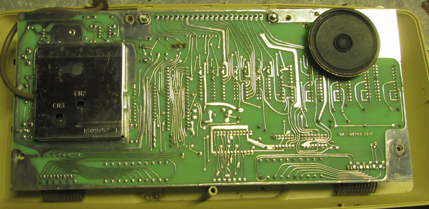
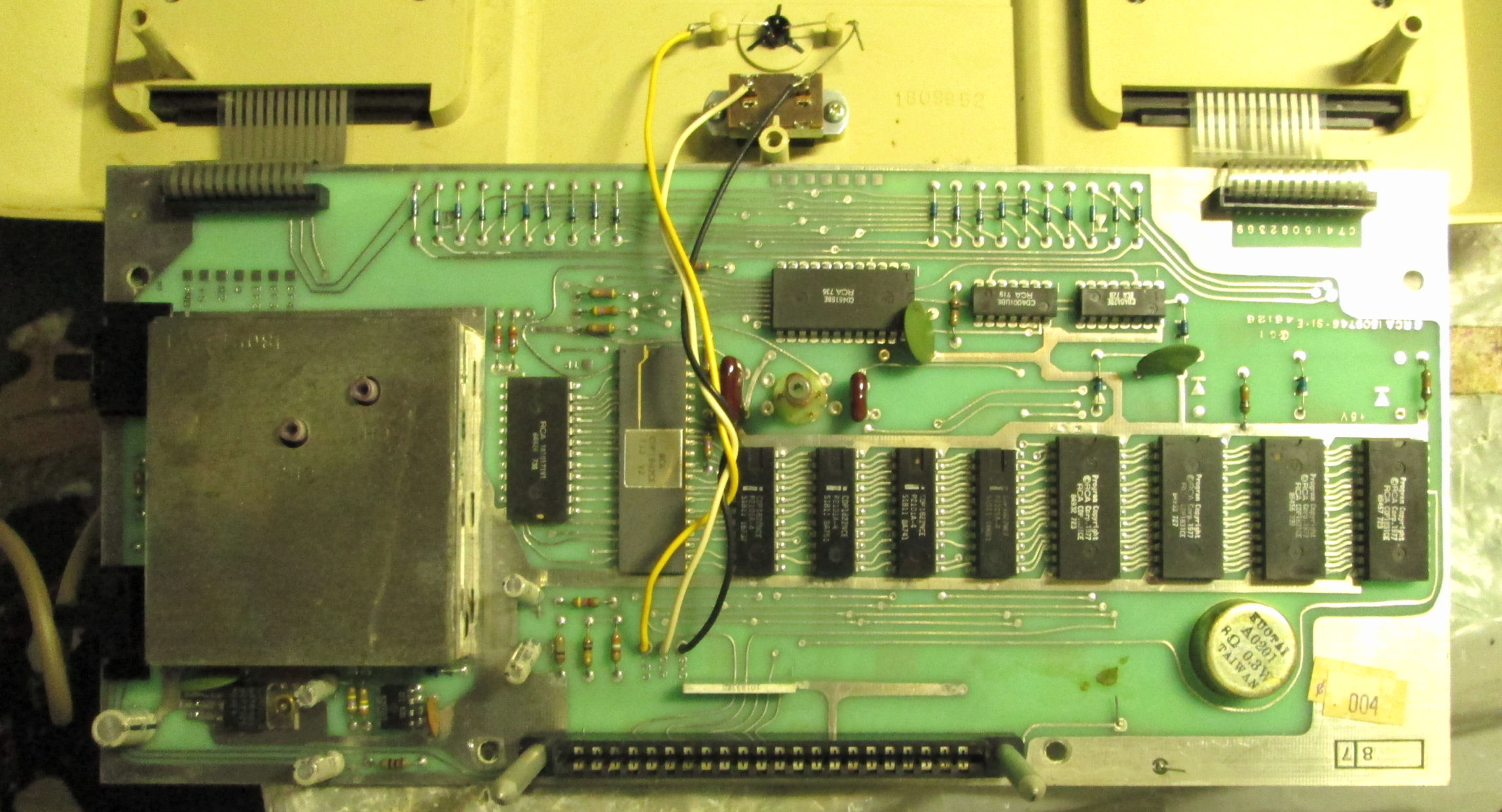
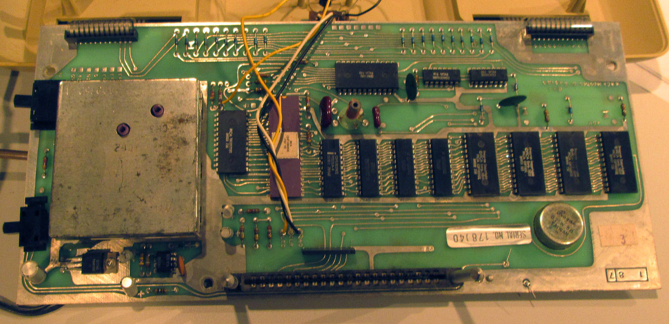
The first Studio II I tested in 2018, was a bit yellowed but looked intact. The screw-seal on the back was intact, I removed the lable to access the screw. The serial number ends in "181" so I'll designate it accordingly. I saw no damage to the solder side of the PC board;, there was a little debris in the case. Same
with the component side. I noticed the memory chips had
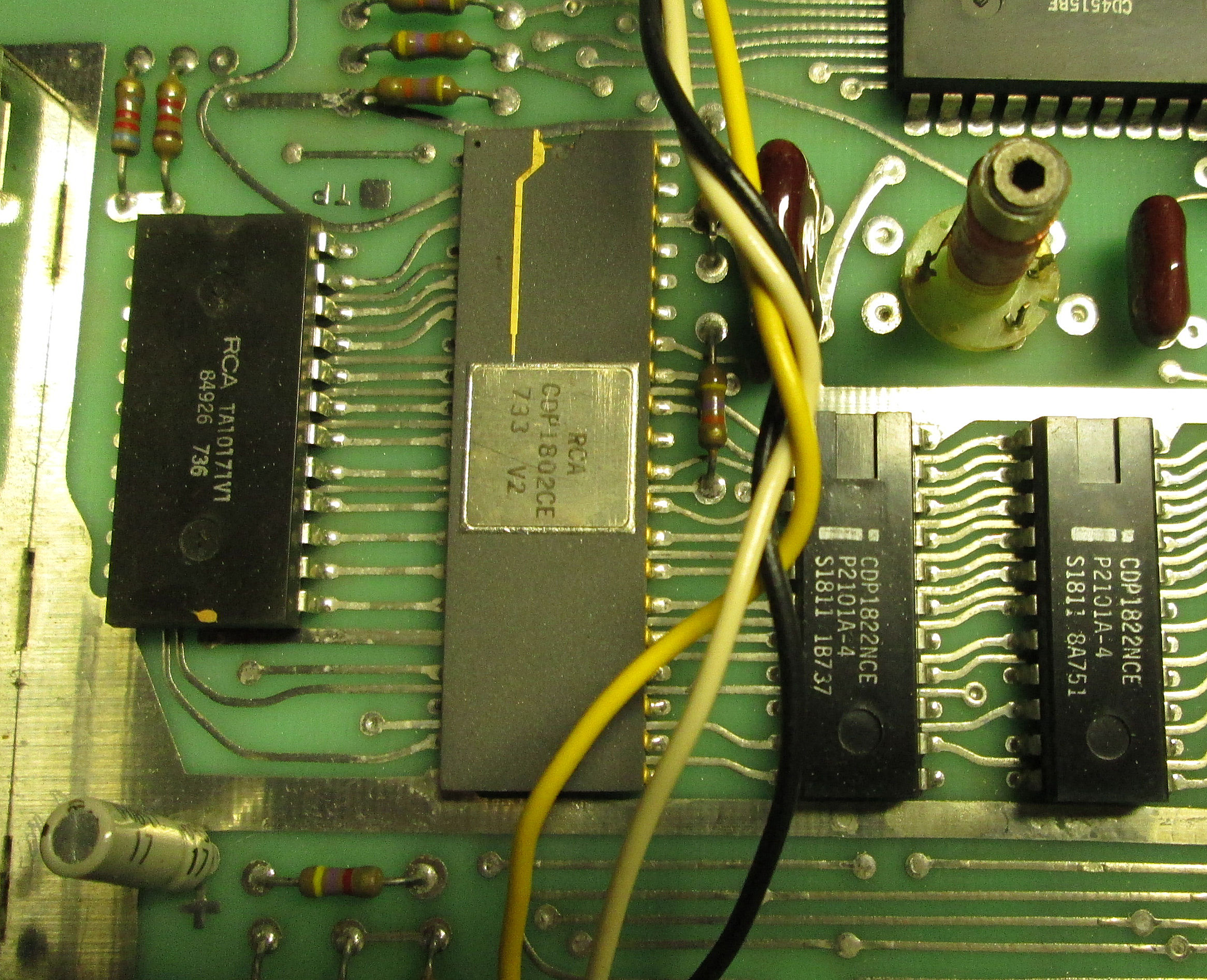
the Intel "I" logo; but RCA part numbers, so Intel must have made these for RCA. Of course the
CPU and video chip were RCA branded, and dated 1977 in the 33'r or 36th week. The 1802 CPU is apparently ceramic, not plastic.
![[RCA Studio II]](stii_gamesw.jpg)
To power and connect the Studio II, I did not have the RCA video switch. That switch has
a connector to the RCA 9-volt unregulated "wall wart" and acts as a DC power-switch. So,
I adapted a Colelco video-game switch (yellow object in photo), and
directly wired a regulated 5-volt DC adapter to the 5-volt lines on the circuit-board. I had to add a "balun" signal tranformer (white cylinder in photo) to the game-switch TV output, to provide a match to the LCD TV's coaxial connector and its impedance.
![[RCA Studio II]](stii_181_bowling.jpg)
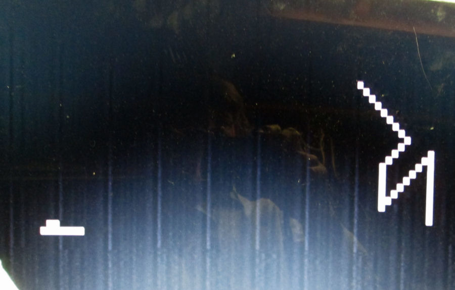
The resulting connections proved successful, as I got correct power to the system (the LED came on) and the audio speaker "burped". The Studio II has a number of embedded games; the first one I
activated from the keypad was a drawing or doodle game as shown.
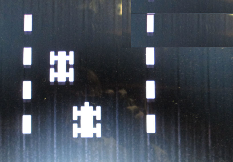
The next game, was a bowling game, and the last a racecar game. The audio is produced through a speaker inside the console; the "tone" is from a 555 audio oscillator circuit that makes only one buzzy tone, of various durations.
![[RCA Studio II]](stii_167_case.jpg)
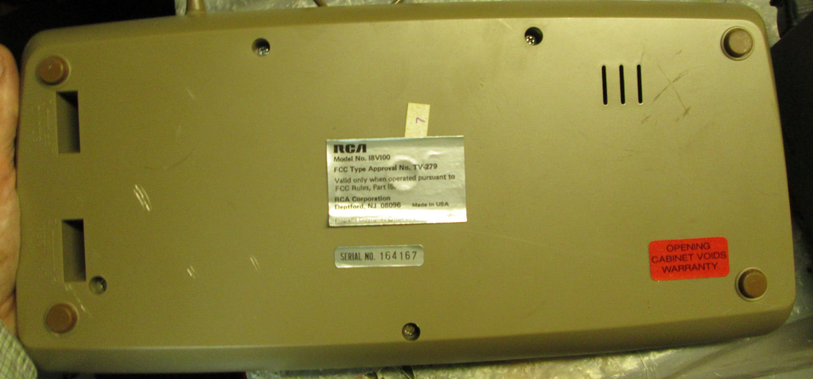
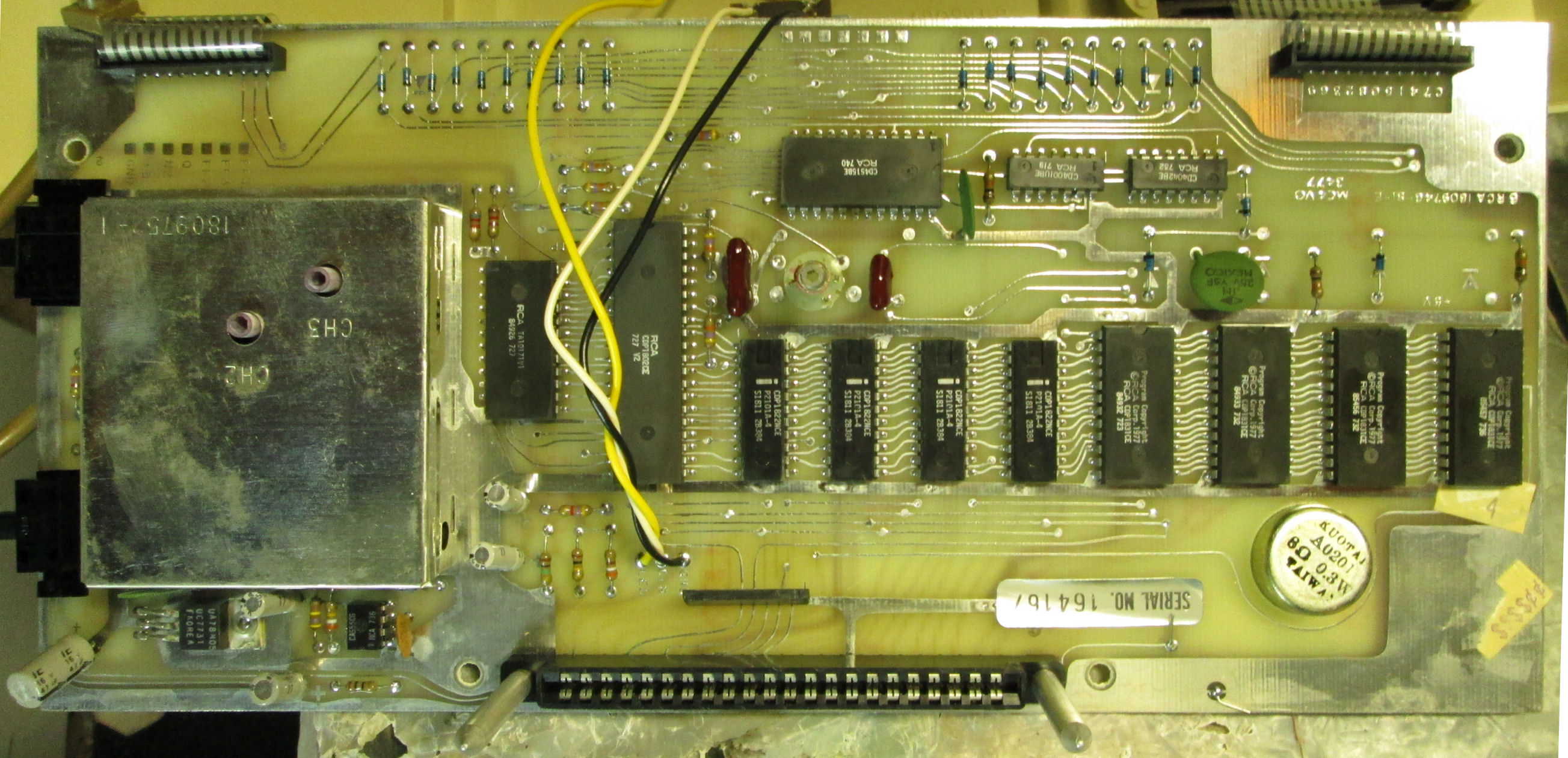
The second Studio II I tested in 2018, was less faded and looked intact. The screw-seal on the back was intact, I removed the lable to access the screw. The serial number ends in "167" so I'll designate it accordingly. I saw no damage to the solder side of the PC board or the component side. The CPU and video chip were also RCA branded, and dated 1977 in the 27th week. The 1802 CPU is plastic. Again, the RAM chips were Intel branded 2101A's.
Connections and DC mod were performed as with the previous unit, and this Studio II performed correctly with its embedded games.
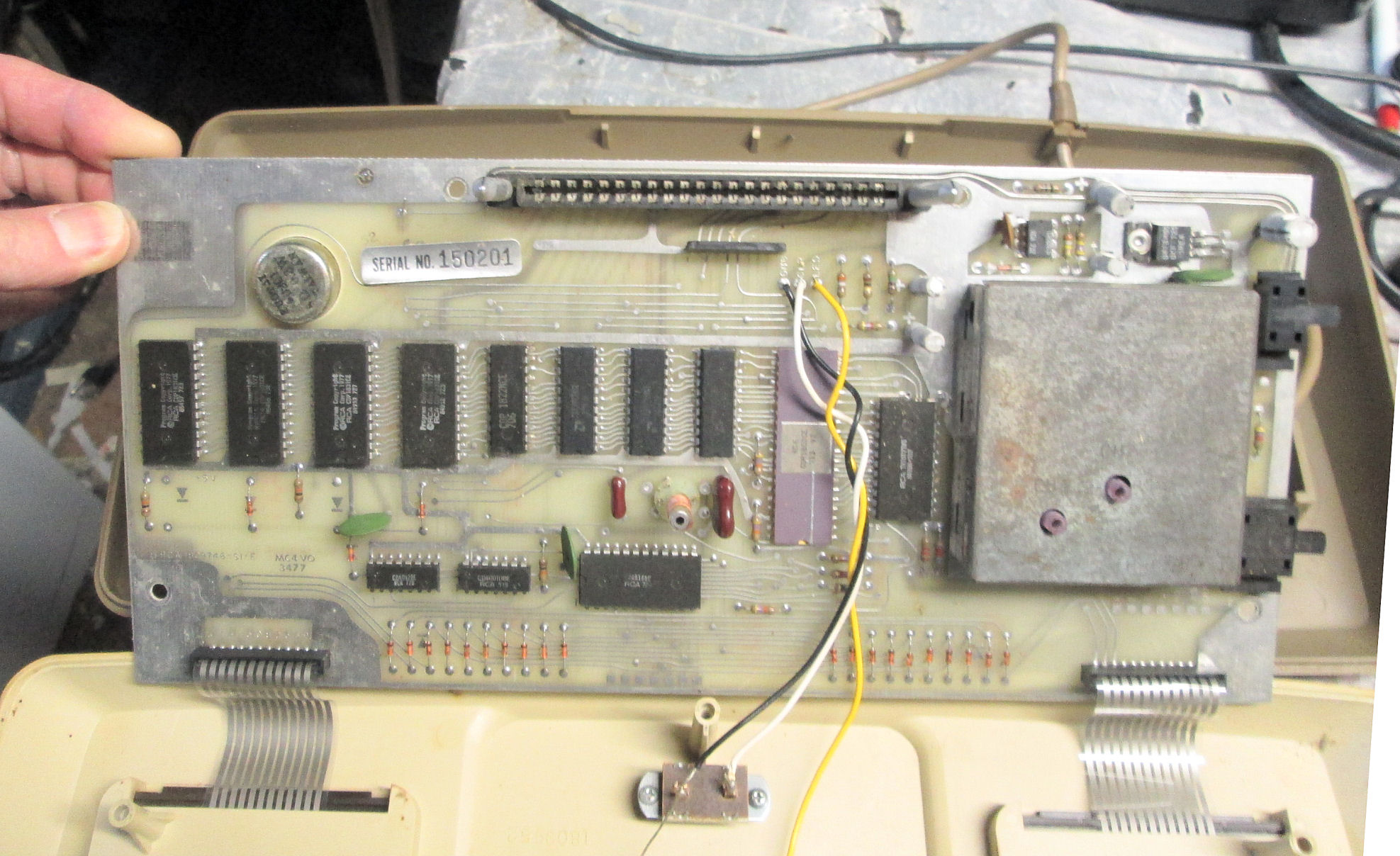
![[RCA Studio II]](stii_201_case.jpg)
![[RCA Studio II]](stii_201_game.jpg)
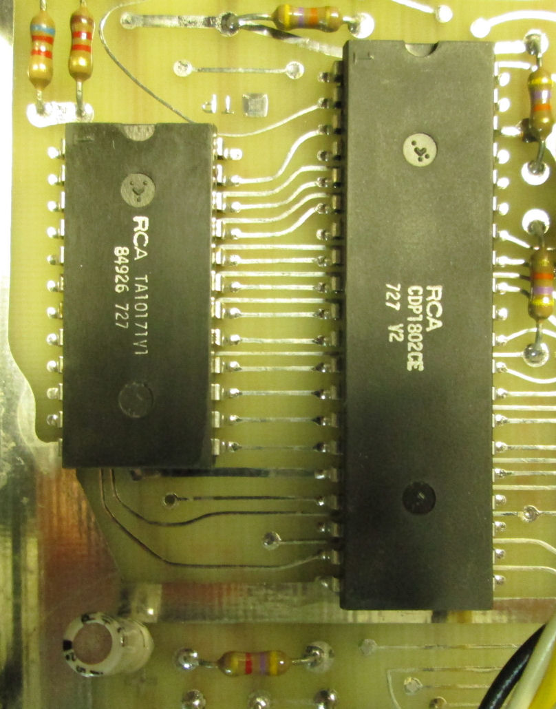
This Studio II unit 150201, I acquired in Mar 2020. The back was bare of lables, but inside was a serial number label. The ICs and such looked OK. The CPU and RCA chips are a mix of STC and normal production. Most of the IC's (memory, ROMs) are dated 1977, the purple CPU has a 733 year/week code, the TA101771V1 plastic IC is dated 707.
When reassembled and tested with RCA external DC wart and TV switch, it showed normal ROM game play. I think the left-hand #2 button felt broken. Also, the channel or
audio toggle switches may have some damage, which for the moment I ignored.
![[RCA Studio II]](stii_568_case.jpg)
This Studio II unit 22568, I acquired in Mar 2020. The back had damaged but intact labels including the serial number. The ICs and such looked OK. When I powered it up, the LED was dim and there was no video.
DC voltage checks showed the DC voltage coming
into the 5V regulator (a TO-220 3-terminal regulator) was 5V in and 2V out. But the DC wall wart was working
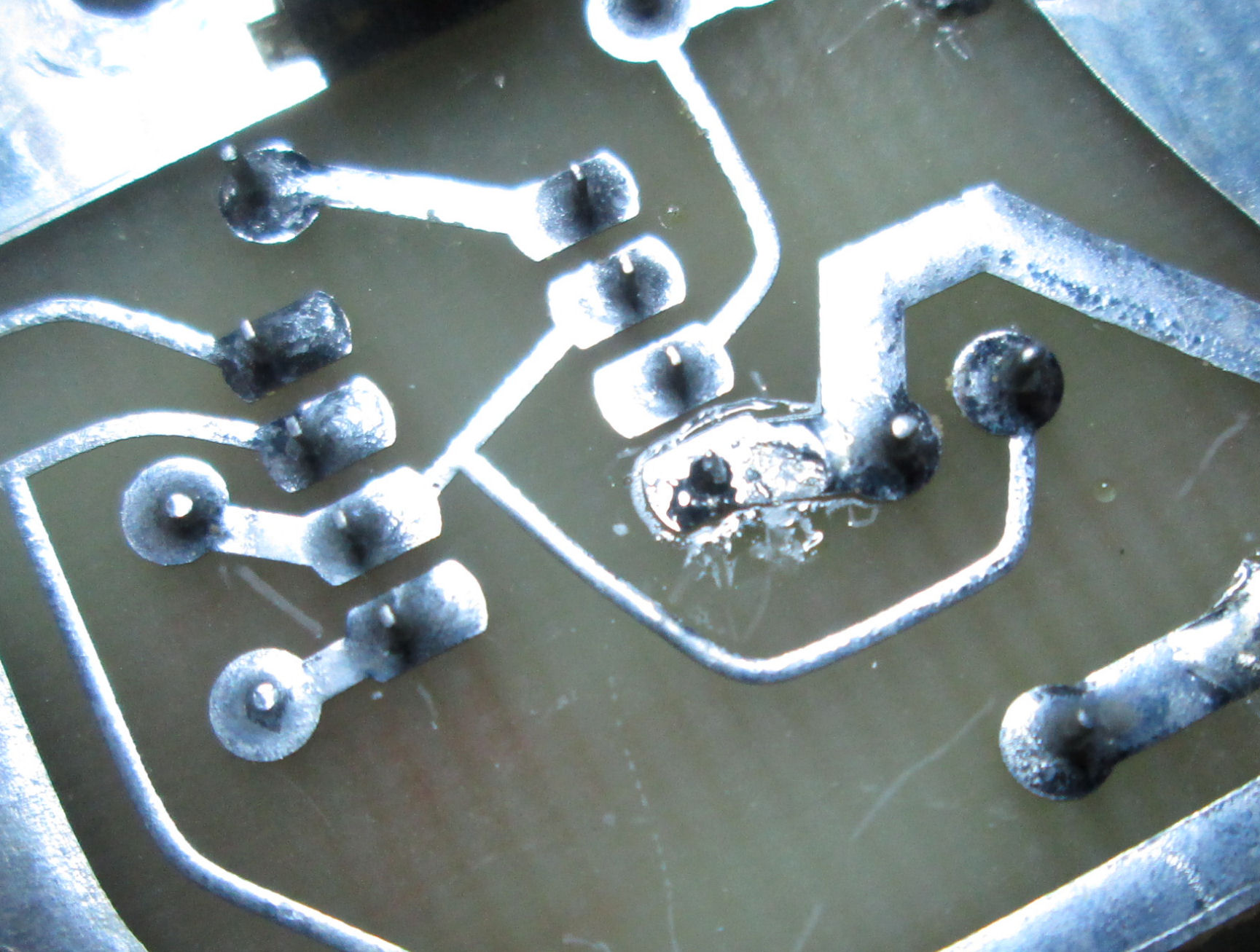
ok. I ohmed out the large caps - they were OK. I did a ohms of the 5V output and it measured 50 ohms - very low. I concluded something was loading down the output regulator and drawing too much current from the small DC wall wart, pulling its voltage down. I did a simple test: I ran the unit and felt the components for heat. The 555 audio chip (8-pin DIP) seemed hot. Indeed, when I sucked the solder from pin 1 of the 555 (the DC power pin) and so disconnected the 555, the resistance on the 5-volt circuit increased.
![[RCA Studio II]](stii_568_game.jpg)
So, I sucked the solder from all eight pins and removed the 555. As I don't need audio to test the rest of the Studio II, I powered it up and it displayed games OK. So I installed a socket and a 555 chip, and games played with audio. There's still an annoying hum...
When I pulled the keypad flatcables from their sockets, I saw they were tarnished. I scrubbed them with a soft pencil eraser, and painted them with DeOxit, a contact cleaner lubricant. I reassembled the unit, and as best I could tell, both keypads worked with all buttons. Audio (such as it is) was restored. While the unit was disassembled, however, I cleaned it up with soap and water and a toothbrush, and some paper towel scrubbing. That seemed to brighten up the unit, and got rid of the penciled scribbles on it.
In March 2020, I acquired two Studio II's with one RCA "9V DC" wall wart and the RCA video game switch. So I could test and repair the Studio II's under normal power and video, no dodges needed as in 2018. I have notes on those systems on this Web page. - Herb
In Sept 2020, Michael Mischna contacted me about repairing a Studio II. He obtained a second one which worked, but it was different: "The Rev. D board (board s/n 16,753) uses a CD4013 and CD4011, while the Rev. E board (board s/n 77669) uses a CD4042 and CD4001. They have different functions, and numbers of pins, and so the traces on the board are different as well. "
Sure enough, among my four Studio II's:
What I call the "181" s/n model has a board number
1809746-S1-E ?G1 46126
logic 4001 4042
The "167" board number is RCA 1809746-S1-E MC4VO 3477
logic 4001 and 4042 lable s/n 164167
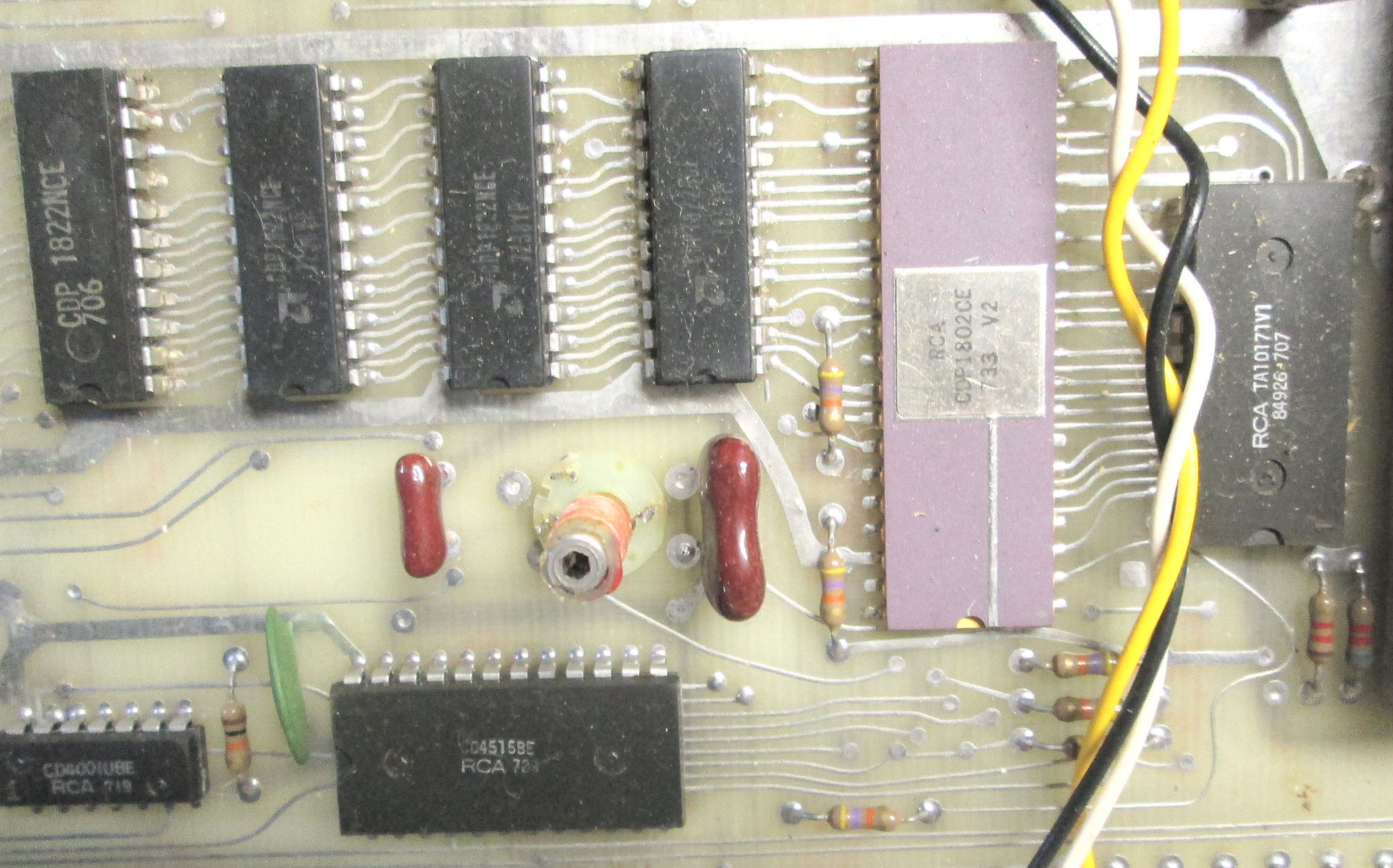
The "201" board RCA 809746-S1-F MC4VO 3477
logic 4011 4012. printed lable s/n 150201
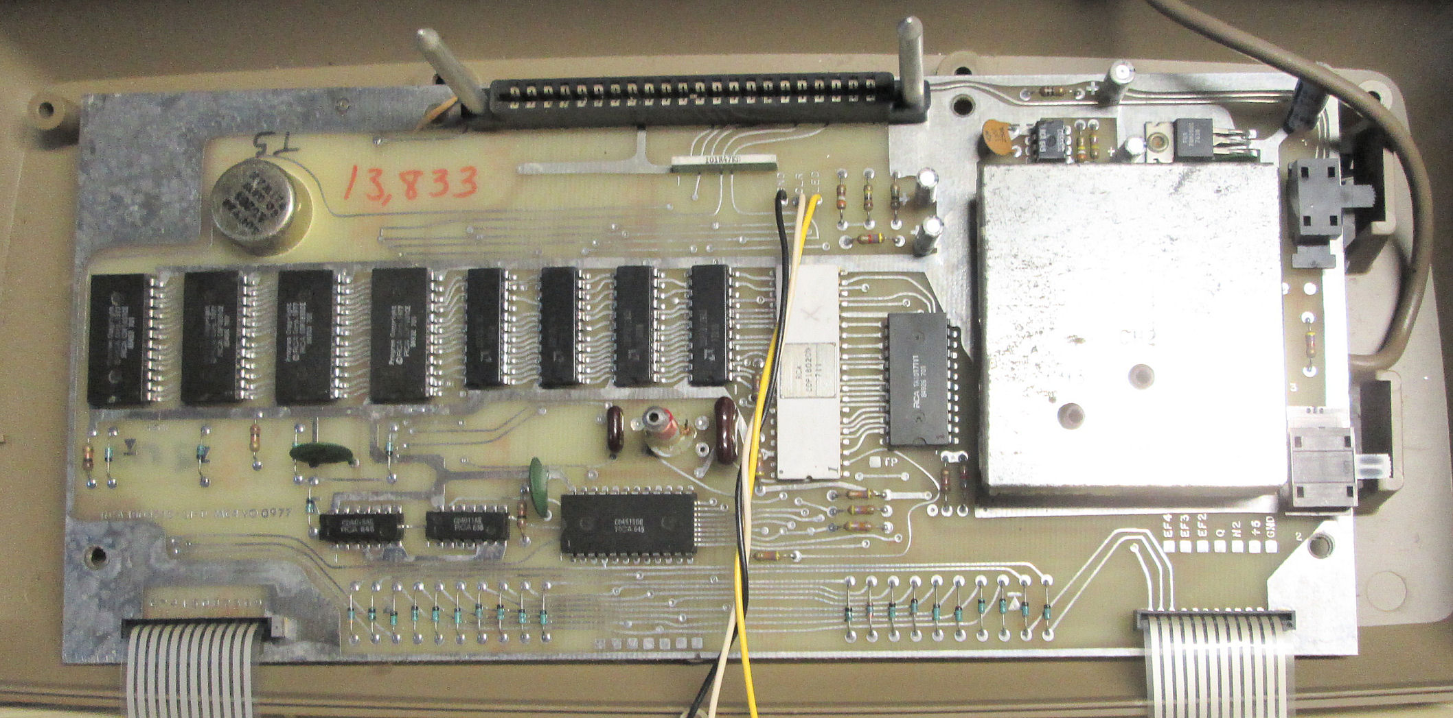
The "568" number is hard to read but ends in MC4YO 0977
logic 401? 4011. Handwritten S/N 13,833
How about that? My rev E also has CD4042 and CD4001; and a rev F with CD4011 and CD4012. And I have a photo from another Web site, of a -C board with CD4011 and CD4013, a 1976 model with ceramic ROMs and 1802.
Also in August 2018, I examined and operated Studio II's owned by The Sarnoff Collection at The College of New Jersey in Ewing NJ. One worked, one did not. My thanks to The Sarnoff Collection and curator Florencia Pierri for the opportunity to evaluate their Studio II artifacts.
![[RCA Studio II]](stii_sarnoff_okconsole.jpg)
![[RCA Studio II]](stii_sarnoff_ok21.jpg)
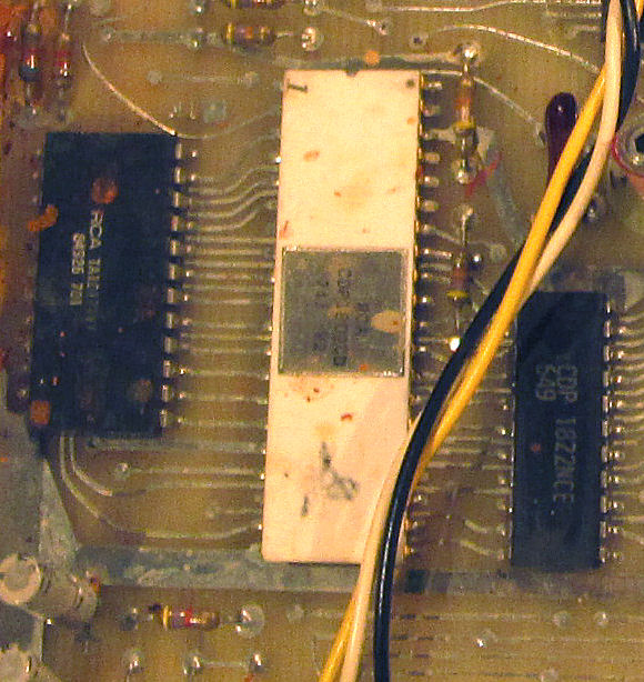
The Sarnoff's first Studio II I tested, was known to have worked prior. It had been modified by previous owners, for an external 9-volt DC supply (connected before the voltage regulator) and for external video. I saw no damage to the solder side of the PC board or the component side beyond the soldered mods. The CPU and video chip were also RCA branded and dated 1977 in the 26th week. The 1802 CPU is purple ceramic.
The museum had a video switch similar to the one I used on my Studio II's, and a Sony Trinitron-brand TV to test with. With those connected to the Studio II and AC power applied, the internal games came up and worked OK, as did the sound. The curator wanted to test some of the Studio II game cartridges she had available; they were coaxed to work by cleaning the cartridge edge-connector with a soft rubber eraser, and by a bit of motion in and out of the console's cartridge connector. In the photo, the Studio II is
playing two hands and a dealer in the card game of twenty-one.
![[RCA Studio II]](stii_sarnoff_bad1.jpg)
The Sarnoff's other Studio II I tested, was known to
have water damage and known to not work. Opening the console revealed rust and small debris on the component side and around the RF metal shield. This unit has a board number in the 23,000's. So, it's no surprise that the CPU and video chip are dated in the first weeks of 1977. The 1802 CPU is white ceramic.
For those with less technical experience with old TV's, video and "TV channels", here's some notes to explain those concepts and the devices I've discussed above. - Herb
Video and power for the Studio II. With the standard RCA video switch-box, the Studio II displays video as an "analog broadcast" signal on channel 2 or 3. A TV of the era would be tuned to "channel 2" or 3 to see the game video. Another example would be an old TV console, tuned to channel 3 or 4, displaying a DVD recording through an "RF converter" between the DVD player and the TV's "antenna terminals".
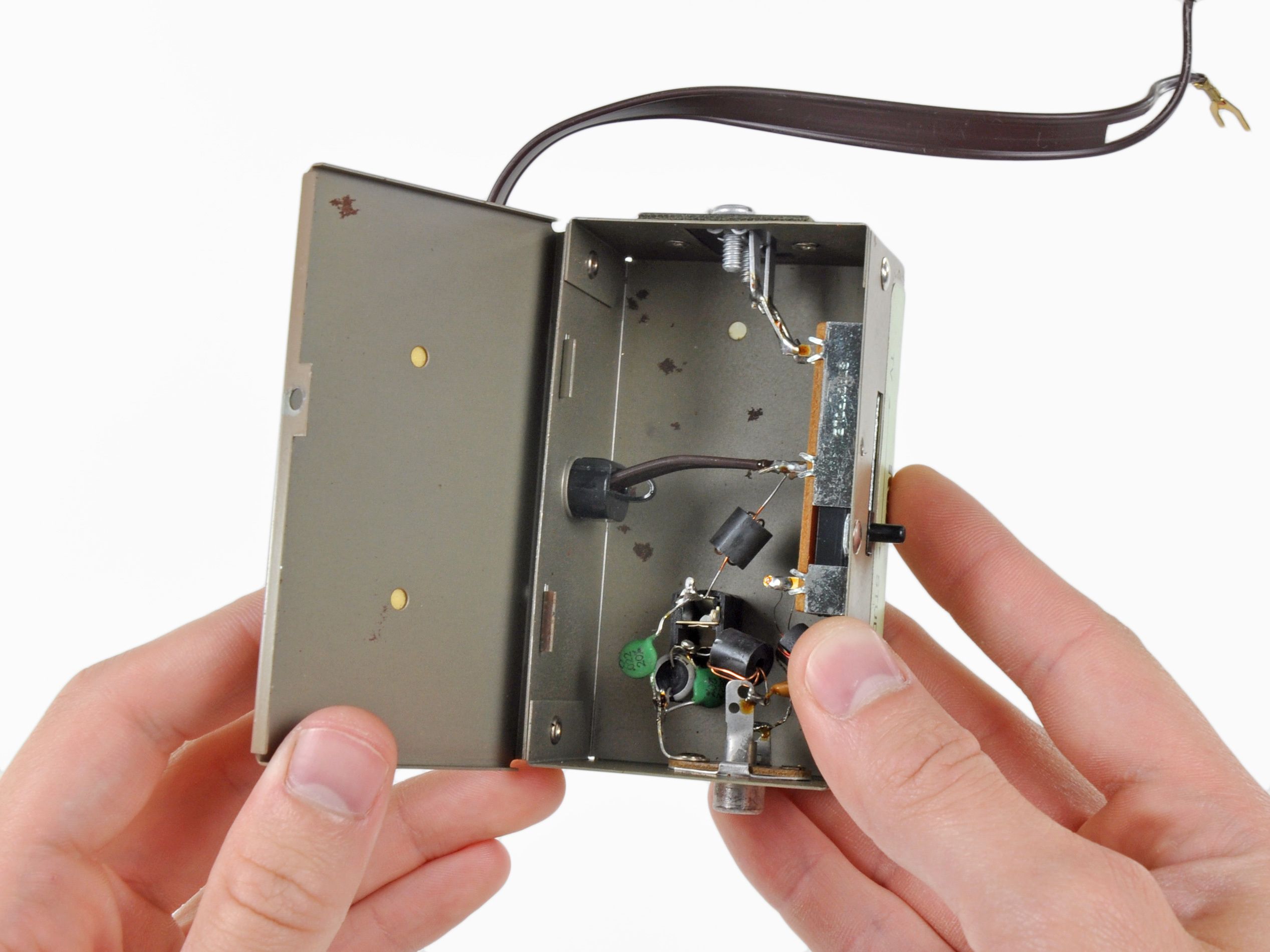
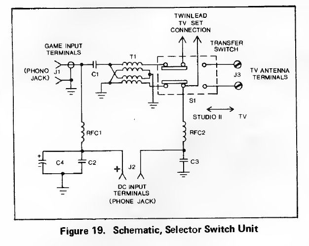
The RCA video switch box looks like this and here's the schematic. Web resources inform me:
C1 = 100 pf orange ‘disk’
C2 = C3 = 0.022 uF ceramic disk
C4 = 47 uF at 16 Volts electrolytic
T1 = five leaded transformer (one center-tap) with ‘Red Eye’ dot,
     from Archer or Radio Shack PK30 kit, Catalog # 273-1601 $2.69
RFC1 = RFC 2 = brown-lead coils in same package as above for T1
     ferrite cylinder wrapped with copper wire.
     probably like "axial RF-VHF Chokes"
I don't have the RCA switch box, which is unique because it also has a DC (power) jack. That connects to the RCA 9-volt power source ("wall wart") sold with the Studio II. For my tests above I used another TV switch box which connected the "video", but had no DC power options.
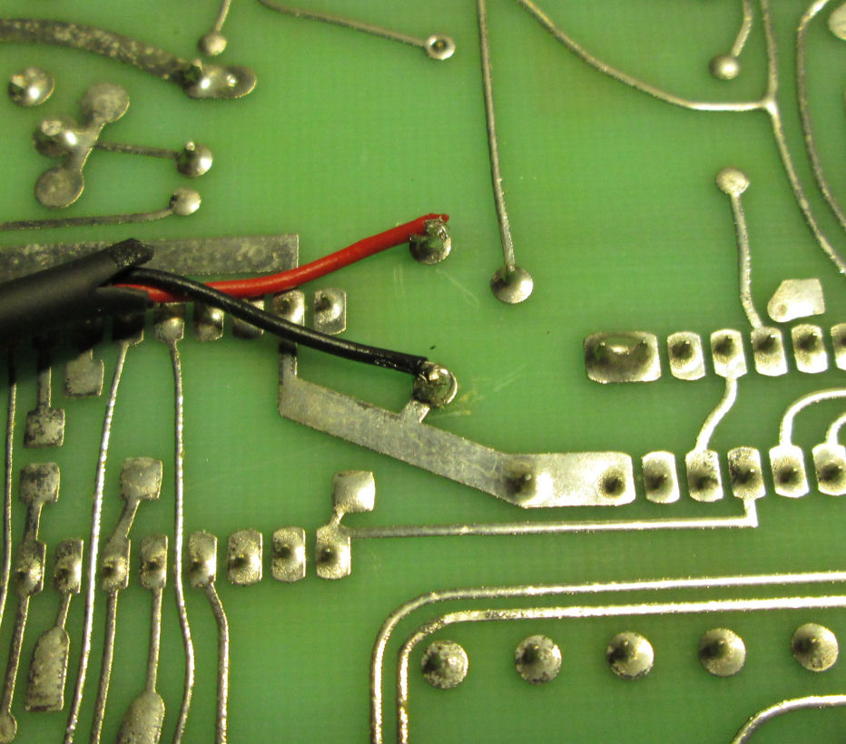
Instead, I directly wired a 5-volt DC power source to internal connections on the Studio II circuit-board. That wired-in source was five volts not nine, because I bypassed the Studio II's power-regulating circuits which produced 5 volts internally. My new DC connections were soldered as shown. Of course reversible with minimal and negligible damage to the Studio II. Cabling was routed through available openings in the Studio II case.
How can you obtain "a video signal" from a Studio II? The Studio II produces "Channel 2" (or 3), which is essentially like the old analog TV transmitted signal for that frequency. Thus an old TV can "recieve" that signal through its antenna connections. But, more recent TV's and other video devices, use a "composite video" connection. That's the video content, without the "broadcast channel" signal. A radio amateur would say the video signal "modulates" the RF Channel 2 "carrier".
I came across schematic information on the Studio II as described above. That suggests I can tap or access the video signal inside the Studio II, with a simple added circuit (one transistor, a few resistors). In due course I'll build and test that circuit on my own Studio II. If it works successfully, that's means to access a Studio II display on more modern and other video displays.
Audio from the Studio II. The Studio II produces audio from a speaker inside the console. You can see the round black speaker, in photos of the circuit board. There's no audio in the RF signal, as with some later video games. A circuit similar to the video-circuit above may work for audio as well. Or, a tiny audio transformer could be added.
One disadvantage of a direct-video or direct-audio connection, is tedious to explain but important because of the "old" nature and risks of vintage TV's. Teh video or audio "mods" described, directly connects the Studio II ground, to the video input ground of some TV or other device. If that TV or device is old and does not operate with an AC power transformer (unlikely but possible), any AC power-line voltage/current on that old device may travel back to the Studio II. That's a potential shock hazard. Such problems were avoided in the era, by using that TV switch; it isolates the TV from the Studio II with capacitors and inductive transformers, such that any AC power current from a TV would be blocked from the Studio II. And, as the Studio II is plastic, there's no conducting path to the user's touch. These TV shock hazards were real and legal concerns in the TV game and early personal-computing era.
![[RCA Studio II]](av_mod.jpg)
Another modification I've considered, is to tap the video from the Studio II, before it's modulated
into the channel 2 or 3 output. This simple circuit was suggested
on on a blogspot Web site. As with the DC power connection, I'd run a video cable from the
circuit, to a connection outside the Studio II.
A number of Web sites cater to vintage computer games; some of them cover the Studio II. oldcomputers dot com has a selection of Studio II clones. These were made in Europe and Hong Kong. Some appear to support Studio II carts, and issued their own games. MOdel and brand names include MPT-02 Victory (Soudic, HOng-Kong); MPT-02 Jeu TV programmable (Hanimex, France), 9016 Telespiel Computer (Mustang, Germany), 1200 Micro Computer (Sheen).
In recent years, people have made multi-game carts with modern ROMs and of course copies
of game-cart ROMs. Some Web searching will find these and inform you if they are available. Original Studio
II ROMs seem to be available for a few or several dollars with some patience.