![[punching mylar]](sol/sol_pun4.jpg)
Most recent revision for this page dated Aug 15 2012.
A work in progress with photos and captions preceeded by a summary to date. I'm trying to produce capacative/foam disks to repair a Processor Tech Sol "Keytronic"-brand keyboard. Requires replacement of metalized Mylar and "foam" plastic disks in keyswitches. Disks are 7/16" diameter and .2" tall. Operation of the key is not conductive but capacative. Here's how I'm gettin' it done. - Herb Johson
PS: To see WHY I am working on this, check my Web page on this Sol computer,
The SOL keyboard has individual key mechs with 7/16" diameter by .2" tall pads of soft foam material with a Mylar metalized layer. That foam disintegrates, and the Mylar breaks down as well. The pads are glued on thin hard-plastic disks, which are held in the key mechamism. Capacitance changes when pushing/releasing the key "stem", squishes the foam - NOT an electrical contact with the metalized layer and the PC board. I needed to remove and clean out the old pads and crud, and install new pads constructed by me from purchased materials and tooling.
I checked the schematic and determined the keyboard produces a 8-bit ACSII parallel output, and only needs 5 volts power. Not knowing the state of the Sol itself, I constructed a simple binary keyboard output display with power jack. Details are described below.
On my first tests, I layered .007" thin polystyrene sheets, and some metalized mylar wrap, between layers of styrofoam plates. All was glued with contact cement. Then I drilled through with a 7/16" hole punch, to punch out the 7/16" disks. I used styrofoam food plates to protect the Mylar. The resulting disks were too hard, the mylar got wrinkled. But the trial established the process was possible.
Next, I tried half-inch thick silicone sheet. This white material was softer than the polystyrene sheets, but too thick. So I had to manually cut the disks down, either by slicing the sheet beforehand, or cutting up the disks after drilling. Results were mixed. When drilled out it produced "conical" shapes because it was squished during drilling. Cutting the material by hand, before or after drilling, produced uneven disks which varied in height and "tilt" from vertical. After selecting resulting disks, they were installed in the keyboard and they MOSTLY worked. This verified the operation of the keyboard with proper pads, but it took far too long to cut-and-try.
I also discovered that variations in pads, remaining crud on the plastic disks or on the PC board, and some problems that seemed to "follow" the removable key "stem" all contributed to faulty key actions.
Finally, I got some padding material of the proper thickness and resiliancy, Woodland Scenics brand foam, thanks to Bill Degnan. I used this to make additional key pads to restore the remaining keys to operation - except for a few stubborn "stems", which I moved to rarely used keys. This material was the best to work with.
At some point, I thought I'd have to diagnose the circuit. I constructed a keyboard map between codes on the PC board, and scan counts on the hardware counters. I looked around the Web for other repairs: here's links to other people's keyboard repairs. Finally, Here's another capacative keyboard for comparison.
- Herb Johnson
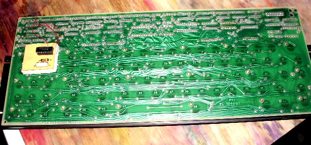
![[SOL keyboard]](sol/sol_kbd1.jpg)
photo of SOL keyboard, full Here's a photo of the back of the keyboard.
Here's a photo of the disassembled keyboard as I'm inserting some replacement pads.
photo of connector to SOL keyboard. I constructed a display of the keyboard output which also powers the keyboard. I describe below how I constructed the keyboard display. It's much more convenient for testing than use of the SOL computer itself.
photo of materials for my first tests. 1) Mylar "metallic wrap" ($1/roll at dollar store). 2) white sheet of
.007" thick polystyrene? sheet ($0.50 at art store). 3) styrofoam plates (40/$1 at dollar store).
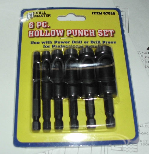
photo of Harbor Freight punch set $10 I used the 7/16" tool.
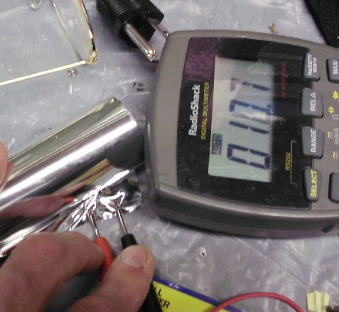
photo of ohmmeter reading to confirm metal side of Mylar
On my first tests, I layered the thin polystyrene with the mylar wrap, between layers of styrofoam plates. Then I drilled through to punch out the 7/16" disks as shown below.
![[test disks]](sol/sol_pun5.jpg)
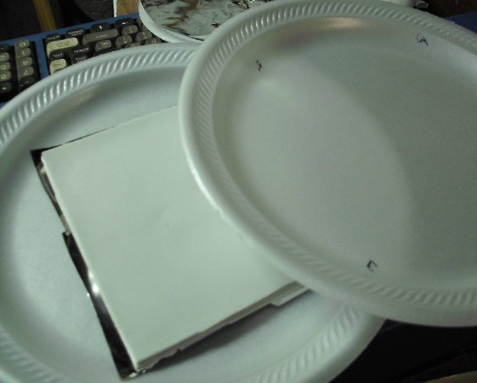
photo of sandwich, Mylar between two styrofoam plates, no glue
photo of punch producing foam/Mylar/foam disks
photo of disks produced, Mylar and styrofoam
I used contact cement (hardware store, a small bottle) to glue up the Mylar to the polystrene, and to make a multi-layer polystyrene "sandwich" to get the .2" height. Again, I used styrofoam plates to cover and protect the Mylar as I drilled through them all. The results were well-formed disks, but the Mylar was wrinkled. Later in use, I found the sandwich was too stiff to use in the keyswitches, so I did not determine if the wrinkling was an issue.
![[first production]](sol/sol_pun6.jpg)
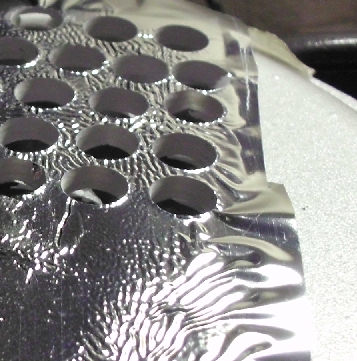
photo of "sandwich" Mylar (conducting side up/glued, three layers of polystrene (to meet .200 disk height for keyboard); all glued with contact cement.
photo of Mylar - styrene*3 sandwich, pressed between two foam plates Dried with weight on top.
photo of sandwich after drying and punching - mylar wrinkled
photo of various punched pads, wrinkles vary. The results were too stiff, so I only used a few polystrene disks in tests with the keyboard.
![[punching silicone]](sol/sol_sili3.jpg)
Next, I tried to cut-down half-inch thick Silicone sheet. This white material was softer than the polystyrene sheets, but too thick. So I had to manually cut the disks down, either by slicing the sheet beforehand, or cutting up the disks after drilling. Results were mixed. Since the material is softer, when drilled out it produced "conical" shapes because it was squished during drilling and contracted afterwards. Also, since I cut the material by hand, the cuts were not parallel to the flat surface. The various disks produced varied in height and "tilt" from vertical. Nonetheless, after selecting resulting disks, they were installed in the keyboard and they MOSTLY worked. This verified the operation of the keyboard with proper pads, but it took far too long to cut-and-try.
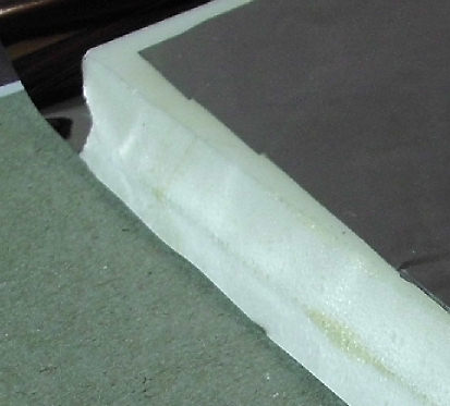
here's the Silicone sheet with Mylar, glued with contact cement. It's glued to BOTH sides, conducting side toward the silicone. Since the sheet is more than twice the thickness, I can get two pads in one, by slicing up the result. The Mylar/silicone sheet is sandwiched between styrofoam plates again, to protect the Mylar.
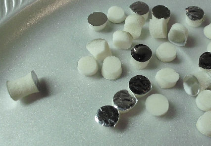
Here's the cut pads. Note the conical shapes, and variations in quality. Here's the final results.
As I needed more pads, I tried to slice the silicon BEFORE drilling. Here's the resulting disks.
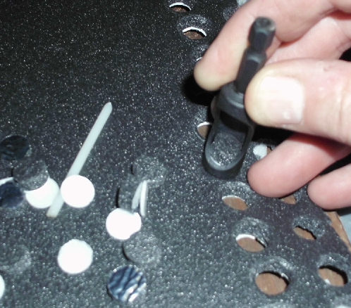
![[punching silicone]](sol/sol_sbd1.jpg)
Here's a closeup of the keyboard with the silicone pads mostly in place, showing some variation in height and angle of the installed pads.
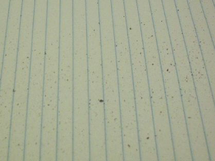
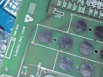
Most, but not all, of the keys worked. Why? This photo shows crap that fell out from the keyboard, when I tapped it over a sheet of paper. Some of that is conducting material, which I think was shorting out the PC board. Other keys did not work, because of issues with the pads themselves, maybe being too short or too long or at some angle - all of which made detection of a press too difficult - my guess.
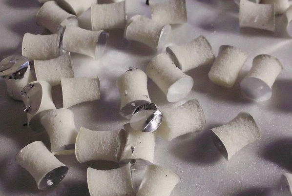
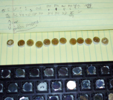
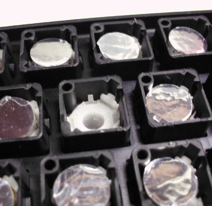
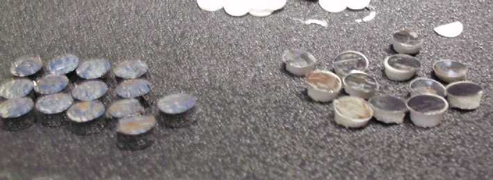
I identified the "bad" keys and removed both keypad and the hard plastic disk which held the pad in the mechanism. In this photo the pads show the plastic disk "up". Note there's a lot of crud on those disks. I removed the hard plastic disks, cleaned off the crud, and reglued them. This seemed to help, I think because the crud made the hard plastic disks too conductive; that may have changed the capacitance. I found it was simplest to clean the disks, by rubbing off the crud and cement between my fingers - like you'd remove rubber or contact cement, which is probably what was used to attach them.
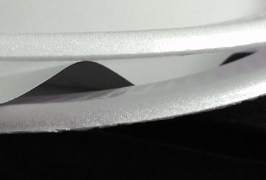
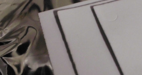
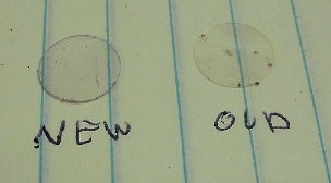
I lost one of the clear plastic disks. So I grabbed some clear plastic packaging from something I bought, and punched a new disk with a hammer and that 7/16 drill punch. Here's a comparison between that "new" disk and one of the "old" ones. It worked fine.
Here's another photo of the silicone disks in place. You can see the variation and defects among them. I fought for hours to test, remake, and replace various pads, and to clean up crud from between the keyboard assembly and the PC board that it mounts on. I kept finding several keys that were difficult to "fix", and a few that came and went in operation.
![[Degan-supplied foam]](sol/sol_degnan_pads.jpg)
As noted below, Bill Degnan acquired some Woodland Scenics brand 5mm foam (3/16"). I decided to give that material a try.
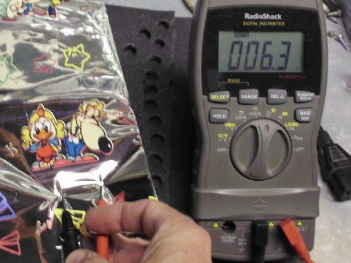
I needed some additional metalized Mylar. After a few tries at the dollar store, I found another $1 roll of metalized Mylar as "metalized wrapping paper". The conductive side was also the printed side - an ohmmeter confirmed.
photo of Styrofoam plate - Mylar - foam sandwich, while contact cement dries.
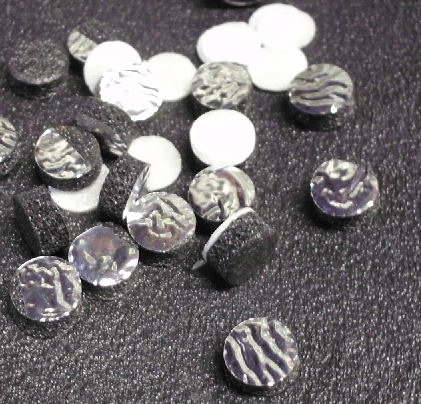
photo of punch at work. I used a hammer to punch out the pads, of course a block of wood underneath to
protect the table and deaden the pounding. Disks produced looked fine, the Mylar wrinkled during drying.
I determined which keys were faulty and removed the old pads, replacing them with new ones. Testing was a tedious process of noting which keys were not responsive, disassembling the keyboard, swapping pads, assembling and test. I took shortcuts. For example, I only put a few screws in, not all 16; I changed which ones to avoid wearing out the threads in the plastic. Again, using the LED tester I built, avoided the fuss of using the Sol just to test the keyboard.
I got down to several keys that needed repeated work. I found I had to throughly clean some of the clear plastic disks the pads were cemented to. Also, sometimes the "stem" of the keyswitch had debris which apparently affected results. Or, some pads I previously constructed required too much force to operate, or operated too slowly. After several rounds of this work, I had maybe three "stems" which didn't seem to work; moving them to another key caused the problem to move with them. I finally put them in key positions I hope I don't need. Another day, I'll try to see why they fail.
- Herb Johnson
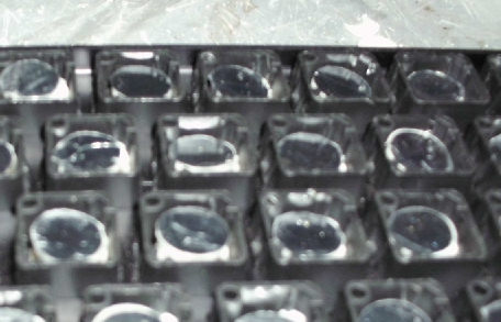
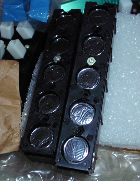
I found I had an unassembled keyboard kit, with the CDC brand, which also used capacitive keyswitches. The "foam" seemed to be in better shape and I was able to confirm that intact pads did NOT have the conductive side "down" on the metalized Mylar layer. IN other words, the metalized side did not contact the PC board.
photo of CDC key switch bank, note wrinkles Note: ohmmeter shows mylar is
NOT conductive-side exposed.
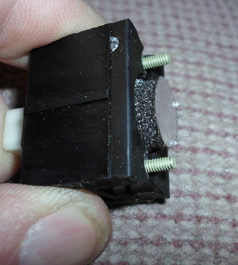
photo of depressed CDC keyswitch. Foam seems intact.
![[keyboard tester]](sol/sol_test3.jpg)
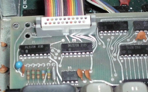
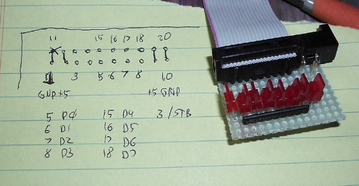
June 24-25: I constructed a simple keyboard output display. The SOL keyboard produces an 8-bit parallel output from a pair of 74LS175 "latches" or quad D-flip/flops; and a "strobe" signal when a new key is pressed. There are no inputs to the keyboard. The keyboard power is +5 volts only, and the keyboard connection is a simple 20-pin 2X10 flatcable IDC connector. Therefore I can power and test the keyboard independently of the computer.
Here's my constructed monitor with 8 LED's. The simplest connection is a "pull-down", with each LED connected to a 330 ohm resistor to +5, and each bit output connected to each LED on the "ground" side. When the latch bit is a TTL low, it pulls down the LED and it will light. When high, there is not enough voltage across the LED to light, and little current is drawn. In the photo, the LED's are arranged from D0 to D7 from left to right; the upper right of the perfboard is a DC power jack. The written notes show the pinout of the connector at the SOL keyboard; the monitor board connector is oriented to the same pattern, pin 11 is the red stripe on the flat cable. I removed the pin from the tester connector and jammed it into the 20 pin connector as a "key".
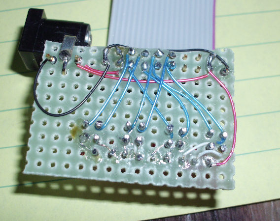
Here's a photo of the back of the tester. Note the DC power jack is now on the upper left of the board. I used wire-wrap wire but soldered all connections, as most of the pins were not wire wrap pins. Black is ground, red is +5V, blue are the data lines. A 330 ohm SIP resistor network was used, with its common connected to +5V. So the LED's are wired between 330 ohms to +5, and to the LSTTL keyboard output which "grounds" the LED (active low) to light it.
Here's the result under power and connected to the UNREPAIRED keyboard. I confirmed of course
that the keyboard is recieving proper power (LSTTL chips almost always have +5 at pin 14/6, ground at pin 7/8.) The photo shows the tester "upside down", so bit 0 is to the rightmost as one would normal display a byte value.
Remember, these are active LOW LED's, so a lit LED is a "0". Therefore the display is 00000111B or
07H; whatever key was sensed. Power-cycling or pressing other keys, did not change the pattern. Also, keys like
caps lock and local don't "toggle" on and off.
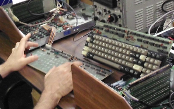
But, with the key mechanisms removed, the keyboard can be operated by touching the keypads on the PC board. The photo shows Bill Degnan operating my Sol, during our Sol repair sessions at The MARCH fit-it event on June-July 2012. I used the tester while re-padding the keyboard and it worked fine.
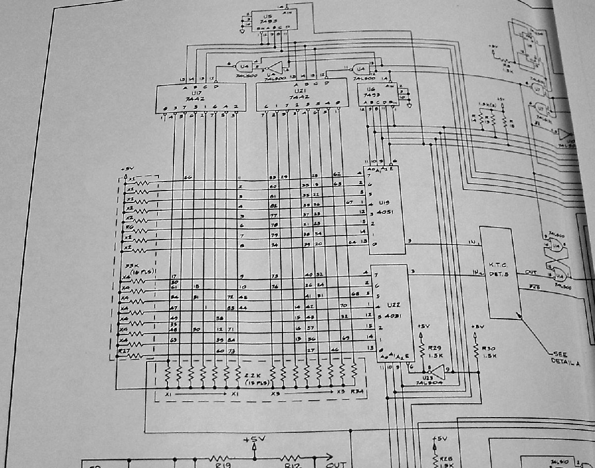
The keyboard is scanned by two hardware counters, which drive some CMOS switches to connect the PC board sensors to a set of analog circuits to measure changes in capacitance. Here's the keyboard portion of the schematic. The Sol manual describes these circuits in detail; I won't cover that. However, the manual does not provide a list of keyboard characters versus the counter's value; or keyboard characters versus a decimal code printed on the back of the keyboard.
So I created a map of characters by QWERTY keyboard position, versus the decimal value printed on the back of the keyboard. Also, a map of scan code versus that decimal value. Here's that map.
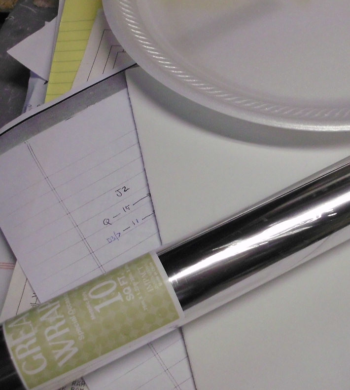
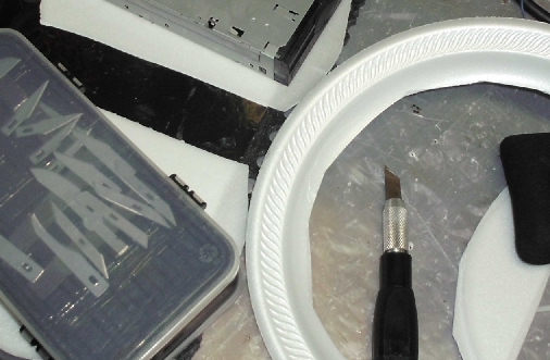
My colleague Bill Degnan repaired his own capacative keyboard. His Web page at vintagecomputer.net shows a Visual 1050 terminal keyboard repair. Here's a quote from Mike L on that page: ".. The foam brand is Woodland Scenics (they're about the only brand you see in the hobby shops). It was 5mm foam (3/16"). [See photo on left. Material provided by Bill Degnan. - Herb]
The space blanket was from WalMart in the camping section, I think (called an Emergency
Blanket). One side of the mylar is conductive and the other isn't. Check
it with a meter and put the conductive side AWAY from the semi-circular
contacts on the PCB. .." Bill Degnan used a punch from a Stanley Grommet Kit, size 1/2" (12mm) punch.
Jim Battle's SOL20.ORG page, the classic reference.
Keyboard repair based on Jim Battles's work.
Apple Lisa keyboard repair Same problem.
Bill Degnan's Visual 1050 terminal keyboard repair.
Copyright © 2012 Herb Johnson