![[cart]](sds_magpak2.jpg)
Most recent revision date of this page, Oct 16 2019. Copyright 2019 Herb Johnson.
In Sept 2019 I acquired a late-1960's RCA cartridge player and restored
it to opearation, as reported here. Why? Well, in July 2019 I obtained a SDS MAGPAK tape cartridge. SDS is Scientific Data Systems; the MAGPAK data cartridge was used on the SDS 900 series of minicomputers. Details of that tape cartridge and recovering data from it, are on another Web page. The cartridge form-factor, turned out to be based on the RCA "Sound Tape Cartridge" or "Snap-Load Cartridge" format. The history of RCA's tape cartridge product is on another Web page. I purchased some RCA carts as well, and then the recorder, in order to play the SDS tapes and to try to recover the data. - Herb Johnson
![[cart]](rca_player1.jpg)
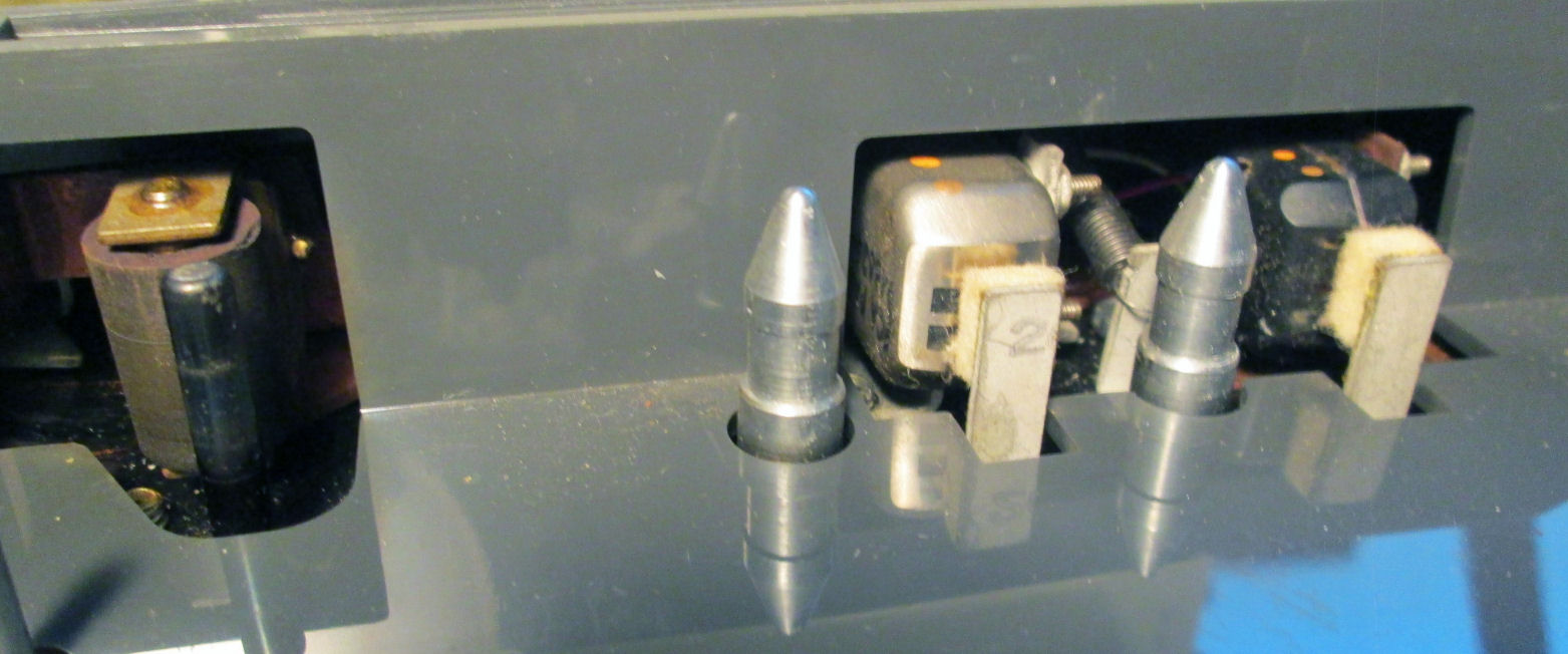
In Sept 2019 I acquired a nonworking RCA cartridge player, a model 1YB-11 mono player, a serial number in the 2000's. It's a vacuum tube model. A view of the tape heads
shows a stereo head with two black bars representing the two magnetic pickups. There's an A/B switch on the
player's deck to select one of these for the one-channel "monophonic" amplifier and speaker. I completed
repairs of the player in late Sept 2019, as will be described on this Web page.
![[schematic]](victor_1YB29_sch.jpg) Here's a schematic published in 1961, from one of RCA's service books, of the RCA Victor model 1YB29 "Flightline" recorder/player. This is not the model I've repaired, but it's representative. It's a vacuum-tube system, not transistor. Note there's only one amplifier "channel" (not two for stereo) and an "A/B" switch to choose which of the stereo channels to play or record. Stereo models also had an A/B switch and I believe a stereo/mono switch.
The schematic shows several vacuum-tube stages; but there's only three physical vacuum tubes.
Here's a schematic published in 1961, from one of RCA's service books, of the RCA Victor model 1YB29 "Flightline" recorder/player. This is not the model I've repaired, but it's representative. It's a vacuum-tube system, not transistor. Note there's only one amplifier "channel" (not two for stereo) and an "A/B" switch to choose which of the stereo channels to play or record. Stereo models also had an A/B switch and I believe a stereo/mono switch.
The schematic shows several vacuum-tube stages; but there's only three physical vacuum tubes.
The tape signals are analog, not digital; the same technology as used on 1/4-inch "open reel" tape recorders of the day by RCA and others. RCA improved audio quality of those tapes, for more fidelity at lower tape speeds. In play, the amplifier gets tape signals from the read/write head and drives the speaker. In record, the amplifier gets signals from the microphone or other sources, and drives the read/write head to put magnetic signals on the tape. Also in record, a stage of the amplifier becomes an oscillator (71 kilocycles) which puts an AC "bias" on the audio signal to the tape. An erase head, contacting the tape before the read/write head, demagnetizes the tape in record mode before it's recorded upon.
There's a switched relay in the motor circuit; that relay is controlled by a switch on the microphone (switch wired to J4), to stop and start the tape as one chooses while recording. Tube EM84 is a "Magic Eye" tube which has a visual display to show volume levels. Recording at too high a level creates a distorted recording, so the user must "turn down the volume" for a quality recording.
Note there's an AC power transformer in use. For safety reasons and because users made regular physical contact with the microphone and controls, the AC transformer removes the (metal) chassis from direct wiring with the AC line. Transformerless radios and phonographs were common in prior years; those had direct contact with one side of the AC line. But they had controls made of wood or bakelite which (usually) kept owners off-contact from the electrically-active chassis. Eventually, safety concerns dictated the use of AC-line isolation by adding such transformers, at more cost and weight.
The schematic doesn't cover the tape-transport system which is the mechanics and motor that move the tape past the heads. The service document suggests the same "transport" was used across several models of
players with different case features and styling.
My 1YB-11 player recorder, has only two vacuum tubes, the 6EU7 and 6DR7 also in this 1-YB-29 schematic. The "magic eye" EM84 or 6FG6 in the schematic, is replaced in the 1YB-11 with a simpler circuit driving a neon lamp. The 1YB-11 has the same CR1 DC rectifier, as a selenium rectifier device. During repair I determined the DC supply produces the same 170V DC voltage.
![[1YB-11]](rca_cart_mech_1.jpg)
![[1YB-11]](rca_cart_amp.jpg) A photo on the left, of the interior of the 1YB-11, showing the amp chassis and the tape transport mechanism. Note the transport is plated with copper! Black marks on the pulleys are the remains of the rubber belt, which turned
to black goo. The photo on the right, is the interior of the electronic chassis; the resistors and capacitors. The
grey rectangular device, is a selenium rectifier; one of the oldest of semiconductor components. The cylendrical
device near the top of the photo with parts (resistors) mounted beneath it, is the electroyltic capacitor. The
construction of the chassis is very typical of vacuum-tube construction of the period. An experienced 20th
century tech could identify all these components and their encoded values by eye. Half a century later, an
electronic technician or degreed electrical engineer of 2019 almost certainly could not.
A photo on the left, of the interior of the 1YB-11, showing the amp chassis and the tape transport mechanism. Note the transport is plated with copper! Black marks on the pulleys are the remains of the rubber belt, which turned
to black goo. The photo on the right, is the interior of the electronic chassis; the resistors and capacitors. The
grey rectangular device, is a selenium rectifier; one of the oldest of semiconductor components. The cylendrical
device near the top of the photo with parts (resistors) mounted beneath it, is the electroyltic capacitor. The
construction of the chassis is very typical of vacuum-tube construction of the period. An experienced 20th
century tech could identify all these components and their encoded values by eye. Half a century later, an
electronic technician or degreed electrical engineer of 2019 almost certainly could not.
![[1YB-11]](rca_cart_motor.jpg)
![[1YB-11]](rca_cart_motor_2.jpg)
Black marks on the pulleys are the remains of the rubber belt, which turned to Tootsie-Roll goo. I had to remove the goo with soapy water and careful scraping. Also in the photo at the upper right, are remains of blocks of compressed paper, used as vibration supports in the plastic cabinet.
On the right is a photo of the motor pulley and part of the mech to swap the belt from one pulley (shown
clear) to the other (shown with black goop on it). The copper wire around the pulley, is moved by the
operator from one pulley to the other, to change speeds by moving the rubber belt. The motor in motion, pulls
the belt onto the pulley. With the new belt installed, the photo right shows more detail of the tape-speed-change mech.
![[1YB-11]](rca_cart_testplay.jpg)
![[1YB-11]](rca_cart_play2.jpg) The photos left and right, show the assembled 1YB-11 player in operation with the tape cart as purchased
together. It's common, to use a Variac - variable AC transformer - in first operation of electronic equipment
that's decades old. A low AC voltage is applied, then slowly over tens of minutes the AC voltage is increased.
Reasons? First, to observe the circuits for any signs of distress including smoke and fire. Second, to
"reform" various large capacitors, and to test them by voltage measurements for shorts.
The photos left and right, show the assembled 1YB-11 player in operation with the tape cart as purchased
together. It's common, to use a Variac - variable AC transformer - in first operation of electronic equipment
that's decades old. A low AC voltage is applied, then slowly over tens of minutes the AC voltage is increased.
Reasons? First, to observe the circuits for any signs of distress including smoke and fire. Second, to
"reform" various large capacitors, and to test them by voltage measurements for shorts.
Results were surprisingly positive. None of the capacitors needed replacement. The DC power supply produced 170V DC - same as shown in the schematic. There was no "hum" in the speakers, the usual sign of bad electrolytics. Sound quality was decent, considering there's only a oval paper speaker in use. And, when the player was engaged into "play", the belt operated as designed, even at low AC voltages (say 80, 90V AC) and the tape played - probably for the first time in decades!
And so: On Sept 23 2019, I heard the result of the april 4th 1974 sports broadcast, of Hank Arron's
714th home run, breaking Babe Ruth's lifetime record. The broadcast followed with a commercial for Coke-Cola's
"real thing", a familiar sound to anyone over 60 (like me). That was recorded, over a family's Christmas dinner
conversation; children and adults, discussing events and things. I know the date from a young boy's statement
well into the tape: "that was a recording of our Christmas dinner, 1969". This was probably the first playback
of that tape since the 1970's, and half a century after it was recorded. - Herb Johnson
![[1YB-11]](rca_cart_bef_azimuth.jpg)
![[1YB-11]](sds_cart_bef_azimuth.jpg)
The audio response of the recorder for the tapes I had on hand, seemed "mushy". That means the higher frequencies weren't very loud. For the home recordings, I assumed that was because they recorded from AM radio. This oscillograph (left) shows some audio from such a tape. But for my SDS data tape with two "audio" tones on it (right), I could see the high-end response was less than the same recording as played on my Wollensak open-reel recorder. What to do?
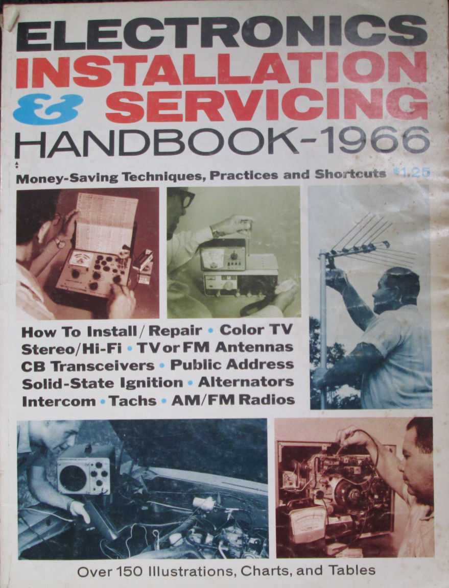
In early October 2019 I obtained this 1966 issue of Popular Electronics magazine's audio-equipment service special-issue. It covered magnetic recorders among other audio equipment. For magnetic tape recorders, it suggested that high-frequency response may be damped by a magnetized read-write head. The cure for this, is a "head demagnetizer", which is simply an AC powered electromagnet, held to the head. It happened I had one; I put it to use. The procedure is important to follow. Hold the demag well away from the recorder; turn it on; slowly approach the recorder and move the probe along the head; then move it slowly away from the recorder; then turn it off. Turning it off and on near the head, may magnetize the head - ask an electrical engineer why. ;)
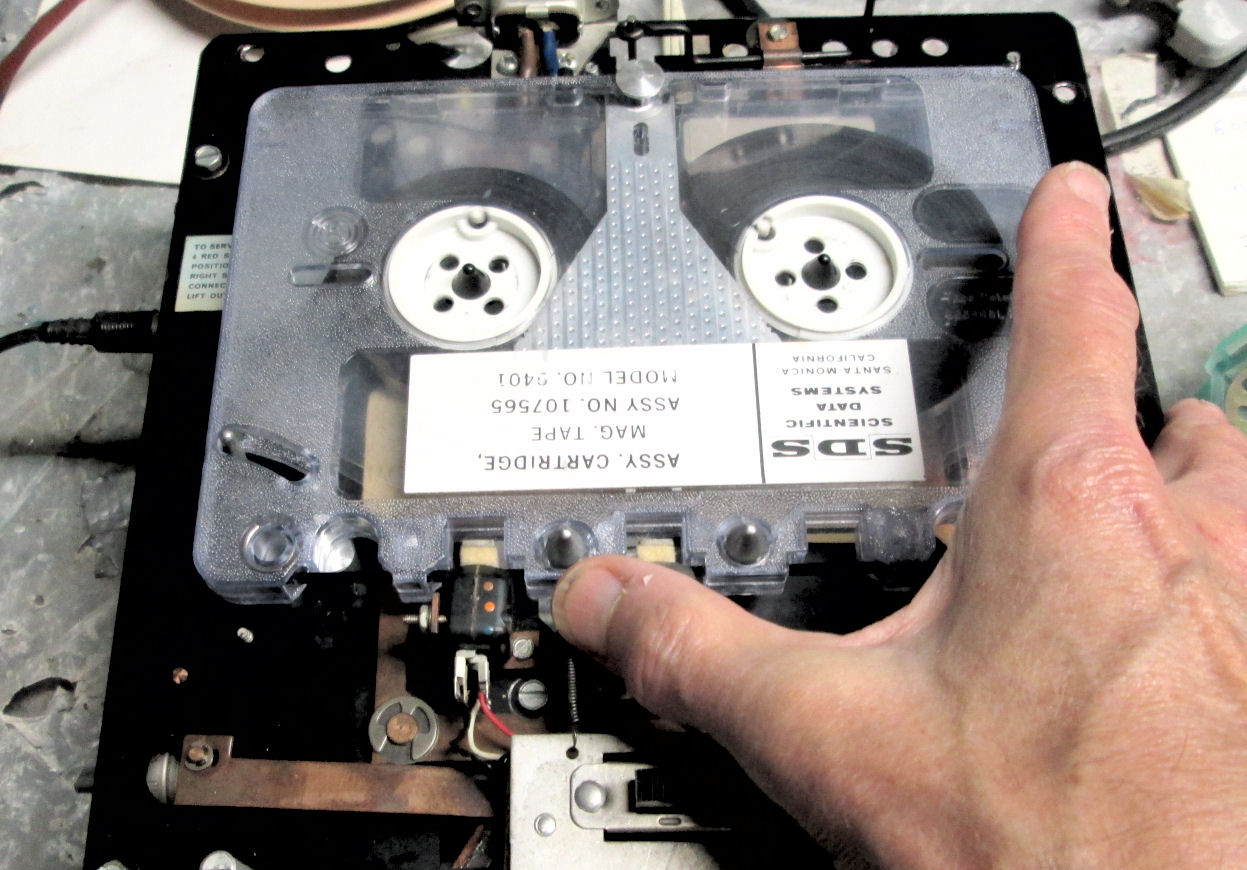
The service information also suggested I check the head alignment for "azimuth". That's the angle of the gap in the read/write head, which must be perpendicular to the length of the recorded track. On the RCA player, the head is mounted on a metal plate, which has a screw for adjustment. But I also found, that I could physically move the head temporarily with my thumb. This "rule of thumb" allowed me to see, that adjusting the head would visibly increase the high-frequencyresponse in both my audio tapes and my SDS digital tape.
Now here's a problem in testing: what's the standard? What tape do I use, as the "correct" azimuth to adjust to? Well, lacking a standard tape, I simply used all the other tapes I had on hand. All of them (execept the tape that came with my RCA recorder) seemed to "brighten" when thumb-adjusting
the recorder-head in the same direction. More to my interests: the SDS tape sounded brighter too with
the same adjustment. As my goal is to recover SDS data, I gave more consideration to the SDS tape. In addition, that tape only has two tones (frequencies) on it, other than noise. So I could more easily
see an increase in high frequency response relative to the lower frequency tone component.
![[1YB-11]](sds_cart_aft_azimuth.jpg) Oct 10 2019: So, I played the SDS tape and watched the oscilloscope display, while adjusting
the azimuth screw with a nutdriver. Over about a one-turn range I found a position which visibly
increased the higher-frequency component of the SDS tape, as compared to the display before adjustment.
Oct 10 2019: So, I played the SDS tape and watched the oscilloscope display, while adjusting
the azimuth screw with a nutdriver. Over about a one-turn range I found a position which visibly
increased the higher-frequency component of the SDS tape, as compared to the display before adjustment.
After this adjustment, I found the audio taped music sounded "brighter", and i could see the
oscillographs of that audio "looked" better at the high end. However, the original tape that came with the recorder, did NOT sound better, it was a little mushier. Apparently, the recorder's head was
out of (relative) alignment, from the time of the recordings in 1975! IN any event, as that tape
was already of so-so AM radio quality - and could be treble-boosted with digital processing - I accepted
that new circumstance. And, I'll soon check an RCA-recorded tape, on its way to me now (Oct 11th).
Oct 12 2019: Popular repair belief is, one should "replace all the capacitors". If you look at the ancient components, an expert eye will see paper capacitors and a "can" electrolytic capacitor. Well.. use of a Variac allowed me to "reconstitute" the power-supply electrolytic. And reasonable measurements of the small caps - using a digital voltmeter's "capacitor" and "resistance" settings - suggested to me their values were within range, and they weren't "leaky" (their DC resistance was high or high enough). (As it turned out, the schematic shown on this Web page, matches the audio circuits in this recorder.) The DC voltages from the the power supply were as specified in the schematic. And there was no audible "hum" in the audio. So I left well enough alone, and replaced none of the 60-year-old components.
![[tiffanys]](tiffany_a1_blow_spectrum.jpg)
![[tiffanys]](rca_cart_tiffanys.jpg)
On Oct 15th 2019, the post delivered my 1962 "Breakfast at Tiffany's" RCA cartridge. Recorded in 1960-61 in Hollywood, originally composed by and conducted for this recording by Henry Mancini. Of course, it's music from the 1961 Paramount Pictures film, staring Audrey Hepburn and George Peppard, and a number of 50's and 60's film musical artists. A host of familiar period names are associated with the screenplay, novel, music and production. The film won two Academy Awards and several nominations, including wins for Best Original Score by Mancini and Best Song ("Moon River") by Mancini and lyricist Johnny Mercer. Other awards include a Grammy for Mancini for Best Soundtrack Album. Details courtesy of Wikipedia, where one can find a description of the RCA 1960-62 released recording.
Consider: this 1/4-inch stereo cartridge was recorded fifty-seven years ago.
After a rewind, the tape ran fine and produced a reasonable-quality audio result. I chose one piece to examine and digitize, because it contained a number of bright percussive instruments. This spectrum of an exerpt from "The Big Blowout" suggests an audio response up to several kilohertz. Manually tweaking the head-azimuth suggested the head was adjusted to the angle of this original recording; so I assume the alignment is "good". Keep in mind: this is a stereo recording and so I could only play one track at a time. I digitized each track of "The Big Blowout" and compared. Observation of each track's digital oscilograph, suggests that almost all the instruments - piano, drums, bass, flute, vibrophone - were confined to either of the two tracks. Only the trumpets seemed to play in both tracks, likely different instruments per track. As I recall from the period, early stereo recordings often segregated instruments and voices, to highlight the then-new stereo effect. The piece runs about two and a half minutes. I digitized it, "flat" without bass or treble boost.
Then, with a little skepticism, under Audacity I combined the two mono tracks, and aligned the starting chords to play at almost the same time - within say 20-30 milliseconds. When I played back the results, I was surprised to hear almost no discord between the two tracks, for the entire length of the piece. One might expect some variation or accumulated delay, which would be audible. But, let's do the math. At a sonic speed of 1000 feet per second, 20 to 30 milliseconds would amount to the delay one would sense from sources only 20 to 30 feet apart. So a consistent delay, if heard at all, would "sound" like seperation in space, or possibly an echo.
In any event, I digitized the piece at 44.1Khz sampling, 16 bit resouution (PCM WAV file), and converted it
to an MP3 stereo recording, which compressed the MP3 file to 25% of the 12.8MB WAV file. So here's a
1962 recording of "The Big Blowout" from Henry Mancini's score of "Breakfast at Tiffany's"; conducted by
Henry Mancini. Copyright 1962 Radio Corporation of America.
- Herb Johnson
Copyright © 2019 Herb Johnson