![[heurikon mlz91]](heurikon_mlz91.jpg)
Most recent revision of this page June 2 2015. Original content here (c) copyright 2015 Herb Johnson.
I constructed a Multibus chassis to operate this Heurikon MLZ-91 single-board Multibus Z80 card. I acquired the card cage,
power supply, and board seperated; in early June 2015 I assembled them together and built a serial cable and serial adapters to
operate the card. Once everything was in place, the card's monitor ROM produced a prompt, as per the documentation. Thanks to bitsavers.org,
for a convenient manual in PDF form; I have the paper docs also. - Herb
![[Electronic cage]](heurikon_caged.jpg)
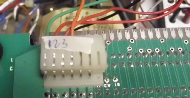
I had a six slot Multibus card cage from Electronic Solutions. It has simple Molex male connectors for power; I salvaged female Molex
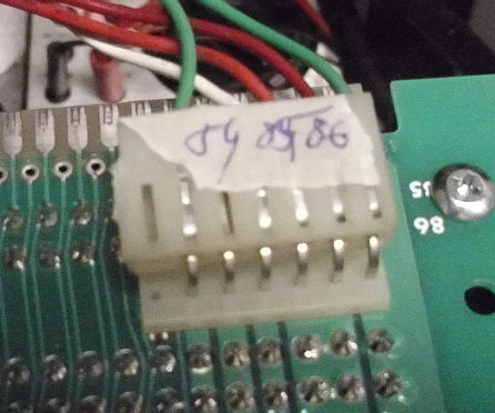
connectors from old Mac power supplies to build the power cables. Here's the connector at pins 1, 2, 3 etc. and
here's the connector at pins 86, 85, 84, etc. as the DC power is split at either pinout of the 86-pin Multibus.
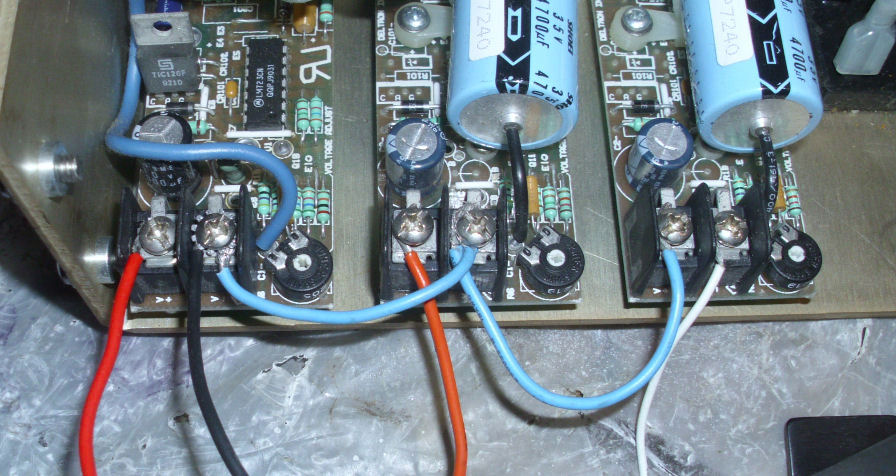
A open-frame non-switching DC power supply provids +5V, and two 12-volt supplies. As all have independent returns, I
chained together the 5V and +12V and -12V returns.
![[serial cable]](heurikon_serial2.jpg)
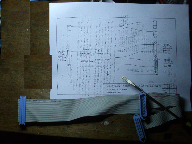
The serial cable required a lot of attention. The Heuricon has a 34-pin edge connector, which splits into two 17-wire cables,
each attached to DB-25 connectors. One is used as a serial terminal to operate the ROM monitor; the other is a printer serial connection.
I made the split cable as per the diagram in the manual. again from old cables and connectors I
had available. I had to build and test a number of serial adapters (null modems, male/female converters, DB-9 and DB-25 adapters)to work
from an old MS-DOS laptop DB-9 to the DB-25's of both my LED serial tester and the terminal connector. After various trials, I found I
was connected to the wrong choice of the two DB-25s! Check and recheck your setup, proves out.
I tested Multibus power first with on the empty chassis, and with an unpopulated proto board. I noted I miswired my -12V supply and had to reverse those connections back on the power suppl. Then I tested on an old scrapped Multibus card which had enough populated chips to draw power. I saw a good +5V on the TTL chips, and saw that -12V and +12V were operating within a tenth or so. Please note: I'm using a non-switching power supply. Do not operate a switching power supply without a load, it will burn up. If you don't know what I'm talking about, look it up. ;)
Futzing with various serial loopbacks and null-modems didn't produce a prompt on my serial terminal program (on my MS-DOS laptop). Checking
and rechecking....looping back thru the cable from transmit to recieve worked. The LED serial display showed the terminal transmit line and the
computer transmit line were on different pins (2 and 3) of the connecting DB-25. A null modem was used to "twist" the transmit, DTR and RTS to
match the receive, DSR and CTS pins. These are paired as pins 2 and 3 for trans and recieve; 4 and 5 as DTR/DSR, and 6 and 20 as RTS/CTS. Please
look up the proper pin designation, don't depend on mine!
![[serial monitor display]](heurikon_prompt.jpg)
Reading the Heurikon docs, it noted that the monitor restarted on reset, as operated by shorting Multibus pin 14 (/init) to ground. I installed an old reset button and cable from an old PC for that, wired to a spot on the backplane for that purpose.
But as noted above, I got success when I used the terminal serial port on the Heurikon instead of the printer port. Changing the connector on the Heurikon cable, I also removed the null modem as the two connectors are wired in complimentary fashion. On reset with the proper serial connections, I saw the Heurikon ZRAID 91 monitor prompt and could execute commands. Later I dumped the ZRAID monitor.Here's the hex records of the 2732A ROM. Also, .Here's the binary file Again, the ROM is addressed at F000H.
- Herb Johnson, June 2015
Copyright © 2015 Herb Johnson