![[ADM 3A 10th terminal]](tenth_altair.jpg)
This page content last updated Feb 4 2024 with correction about ADM3A 10th vs ADM3. This Web page is about a Lear Siegler ADM-3A Tenth Anniversary terminal. I describe the original ADM3 and ADM3A terminals on another Web page. I describe other terminals on a terminals Web page. You can contact me from the information at the bottom of this Web page.
During Nov 2019, George Hunt asked me about documentation for a "ADM3A - the one with
the NS405 mcirocontroller". Unknown to me, Lear/Siegler made a tenth anniversary
ADM3A, with a microcontroller chip instead of the TTL logic of the original ADM3A.
George obtained such a terminal, and shared his repair work with me in Nov and Dec 2019.
The following texts is edited from his correspondence. - Herb Johnson
Since you are custodian of things ADM3A, I'll pass my notes on to you while things are fresh in my mind. Feel free to use or disseminate as you wish. Attribution would be appreciated.
Nov 25 2019: I acquired a nonfunctional ADM3A a few years back and I discovered when recently starting the restoration that I had the vintage electronic version of a "Black Swan" [a 10th anniversary model]. [Later will be] my comparisons to the standard ADM3A. Restoration was completed (?!) 11/2019
I now have two functioning ADM3As. One is standard and the other is the 10th Anniversary Edition. I need to hack up a lower case character ROM for the standard one and make replacements for both covers for the setup compartments next to the keyboards. Why is it that these covers are almost always missing? It's interesting that the 2 power and 12 pin Molex CRT unit connectors are the same as with the earlier ADM 3A
The first note is my observations on the 10th Av one with close up pixs and a link to the User's Manual (Apr '86). I'm still missing and need the Maintenance Manual. The second note is on the various repairs necessary to get both working.
The ADM3A is an icon from the early days of personal computing and I feel good having two running in 2019. Now my Altair 8800 and Altair 680 have something to talk to/through.
- Regards, George Hunt, w4avo.org
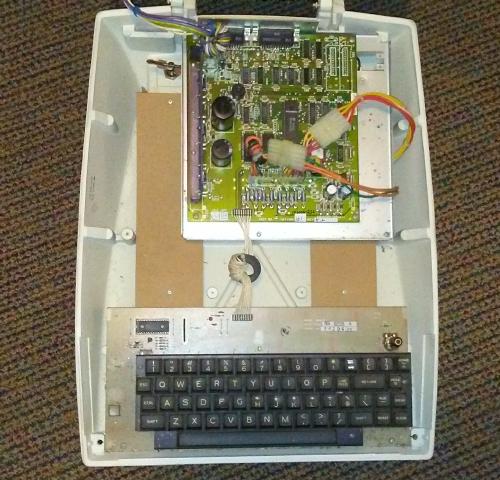
inside the 10th
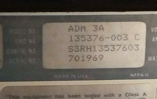
nameplate
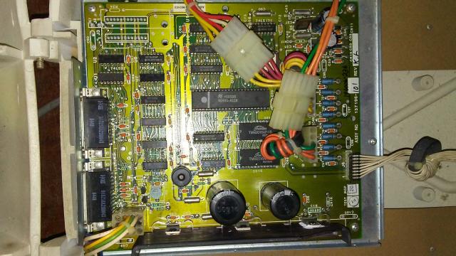
logic board
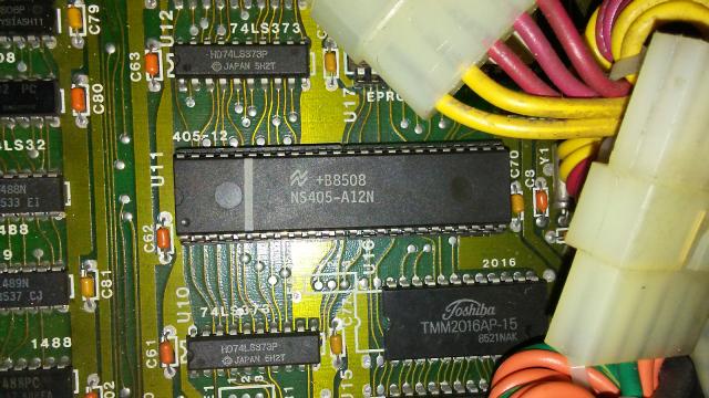
terminal chip
video board
working terminal with MITS Altair 8800
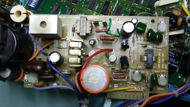
External - Rear name/serial# tag = ADM3A 701969.The set-up compartment to the left of the keyboard has a single button as opposed to a bank of DIP switches. The case and keyboard are the same The power cord, fuse, switch, and two DB25F data connectors are the same Operation - Powering up it beeps and shows "ADM3A V3.1" on the screen Set up is via an on-screen menu and keyboard using the single button set up button 12/24 line and upper/lower case are standard Many more configuration parameters available than in the earlier version (e.g. key clicks) Internal - The CRT unit is Samsung and is plug compatible (4x3 molex) with previous [ADM3A] (I tried it) The sweep electronic board is same form factor and edge connector but different circuit The keyboard is on its own board The control board is smaller Terminal control is via a NS405 micro-controller Documentation (or rather lack thereof) - Web search yielded little info that this product even existed I found [available on bitsavers.org] "Tenth Anniversary Edition ADM 3A Dumb Terminal Users Reference Manual" I am still searching for a Maintenance Manual with schematics
I restored two ADM3As- One was a conventional [TTL based ADM-3A] unit and the other was the rather unusual 10th Av Ed. Fixing ADM3As is a challenge due to less than complete documentation and the age/condition of most examples. Being able to pull and replace a dip on an aged circuit board without destroying pads and plated thru holes is a needed skill. I got better after a few. A triggered scope is almost essential for troubleshooting. Working without a schematic is [tough] but gives you the chance to show how good you are.
Your unit failures will probably be different from mine but maybe these notes will help.
Dead video -
The [dead video] problem [on the 10th Anniversary ADM-3A] was a failure on the [Samsung monitor video] board. Traced the pc board with no schematic to a open winding in the flyback transformer causing a loss of the +34v DC collector voltage to the 2N2219A bias/video amp. The flyback is probably unobtainium [as a replacement part]. I'm going to hack in a $3.25 Amazon +15v to +34v "buck-up" [DC-DC power converter]. [That repair worked.]
Note from Herb: Apparently the flyback produced AC, which was rectified to produce 34V DC, to DC bias the video transistor to the CRT cathode. So, adding a seperate DC supply provided that DC bias voltage. Good news was, the rest of the flyback worked, and produced HV for the anode. So maybe that was an independent winding, or the failure was at the tap.
CRT screen cataracts-
Others have addressed this. I was lucky, both my units (one Samsung, other Sylvania) had clean and bright CRTs.
Missing voltages-
Both my units had bad 3-terminal regulators. It's a good idea to check all supply voltages FIRST. If any voltage is present but low, look for a shorted chip or cap. Use your fingers and feel for hot. Replace any leaking or swollen electrolytic capacitors.
Missing RS232-
I had a unit that would work in local but wouldn't talk to/from the RS232 port. I'd seen that before. Long RS232 cables act as antenna for ESD and feed it right to the interface chips. Replacing the 1488 and 1489 fixed the problems. If I remember correctly, later versions of these chips have better ESD protection.
Memory issues-
ADM3A uses 1k x 1 static ram (2102 or 91L02), 14 ICs for 24 line-uc/lc. Usually a bad chip shows up as strange characters on the screen where you expect blanks. Finding which chip is bad is a challenge. The chip select and address lines go to all the chips H12..16; hence the problem identifying which memory chip has a short. Jameco (and maybe others) still have 2102s at less than $2 ea. If I had memory issues again I would pull all of them and replace with new socketed ones
Double cursor-
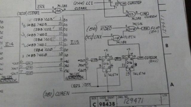
This was a strange one [on the ADM3A]. See pix. There was a double cursor on the screen in both the underline and the block cursor modes. For most column positions the left (earlier) one was in the correct position. Every fourth ( a hint! ) column position the later (right) was correct.
Going to the schematic (see pix) you see that the cursor generation is the product of matching the row/column of the desired cursor with the fast running row/col scan. Output of pin 6 of E15 (see pix) is the cursor just before a 2 col delay and mixing with row character video. RETURN key sets the col to 0. At the wrong cursor, CC1 was hi, WC1 was lo, and =OUT was hi. This is inconsistent with how a 74LS85 is supposed to work so I took a chance and replaced it. .Bingo! now correct cursor.
Nov 30 2019: My older ADM3A is missing the lower case chip. The 10th AV has upper/lower case built in the microprocessor. I have downloaded a lower case rom ( 2513L.bin ) from [an unavilable Web site] and have looked inside. I'll send you what I found if you are interested. I need to get my 2716 eprom pgrmr working to make a 2513 ADM3A lc 2513 replacement. - Regards, George
Note from Herb: Here's a ROM binary from bitsavers.org. Check there for other ADM3 documents. - Herb
Dec 1 2019: Notes on uppercase/lowercase (uc/lc) for the ADM3A
From the ADM3A schematic sheet, Bit6 of the ascii code and state of the internal {lc en}/<{uc} switch determine the chip selects for the uc (L15) and the lc (L14) character roms. L15 is selected if bit6=0 OR {uc}.Ā L14 is selected if {lc en} AND bit6=1.
The 2513 uc and lc character roms are organized as 64 char x 8 rows : 5 bits. The characters are 5 cols wide and 7 rows high (5x7)
The upper 6 bits of the 9 bit rom address is the ascii code for the character with bit6 omitted. For the lc rom these 6 address bits are inverted. The lower 3 bits contain the row address for the dots with the zero for the top. The rom 5 bit data output horizonal dots for a row with msb leftmost.
2 extra 2101's are needed (J11 H11) for the extra bit in lc ascii codes.
It may be possible that the Signetics made these 2513s custom for LS and other 2513 character roms may not be compat.
A replacement for the ADM3A 2513 lc rom --
File 2513L.bin is for a 2716 eprom. It is said to provide lc for a ADM3A that is missing the original Signetics masked rom. This binary file is 2048 x 8. The data is repeated x4. Each fourth looks like it is a image of the original 2513. If I understand the GNU license, it is free to use. The 2716 is not pin compat with the 2513 unfortunately.
I wrote a short program in Pascal that reads 2513.bin, computes and prints the rom address and the 5x7 character using ASCII characters per pixel.
Since finding a lc rom for the ADM3A is unlikely, I may build a 2716 version using the esocop.org plans as a guide. I need to get my broken 2716 programmer working or I may switch to a 2708 or 2704 for which I have a programmer that works. The 2708/2704 needs +12v not avail on the 2513 socket so a +12v 3term reg may be needed if I can't find +12v somewhere on the board.
OR- I may just give up on lc for this ADM3A since it is mated to a 1976 Altair 8800 which doesn't like lc too much anyway. Lower case in my other ADM3A (10th av ed) works fine. - George Hunt
Aug 2022: George says: "I programed the 2513L.bin into a 2716 and bought the misc parts; but it's still on the "soon" list .."
Copyright © 2024 Herb Johnson
![This was a strange one [on the ADM3A]. See pix.](tenth_cursor_bad.jpg)