![[kit]](todd_step1.jpg)
Last updated Feb 13 2020. Edited by Herb Johnson, (c) Herb Johnson, except for content written by Lee Hart and others. Contact Herb at www.retrotechnology.com, an email address is on that page..
This Web page discusses "single stepping" the clock of the COSMAC 1802. There's eight clocks per fetch of an instruction or its operand byte. An "instruction step" would have to cover a varying number of clock cycles depending on the opcode (instruction). A number of single-clock solutions are discussed. - Herb
In May 2015, Todd Decker reported to Lee Hart, that he had trouble with the OUT 5 or OUT 7 instruction to feed data to the LED latch. So he built a single-clock stepping circuit to check out the design. This page describes the design and use. For the discussion of how Todd and Lee debugged the OUT circuit, check this linked Web page. The Intersil 1802 data sheet is on this site as a PDF file at this link. - Herb
May 15, Lee Hart: Here's how it's supposed to work during the 1802's the execute cycle of an OUT 5 (or OUT 7) instruction. See if you can track through this to find out why yours isn't doing this. - Lee Hart --
July 2: Here is a link to a short videoshowing a working set-up for single-stepping the membership card. I got everything set-up tonight and will tackle actually trying to figure out why my OUT 5/7 instruction isn't latching anything either Friday night or Saturday. I hope you guys forgive the corny video, but I wanted you to see things working.
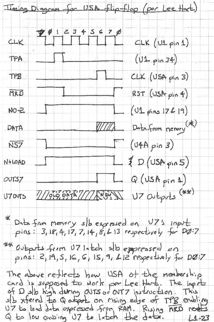
I've also [created these images:]
The first is a quick circuit diagram of the [single stepping] set-up I'm using.
The second is a non-ASCII art version of the timing diagram.
Lee--Could you double-check the timing diagram for me?
Herb--Please do feel free to publish these onto the excellent web page you are building. Since I just breadboarded it out, it isn't really an upgrade but I suppose someone else could adapt it into a more interesting design. Perhaps even putting a down counter on it preset to the number of clock steps needed to truly step from one instruction to the next. But, I believe I recall seeing a more proper "single-stepping" circuit that could be used for this type of purpose. - P. Todd
Lee Hart: "Connect your external bounceless pushbutton to pin 13 of the 4093. This over-rides the 22pf capacitor C1 and resistors R1 and R2."
Todd, July 16:I finally was able to make the time to use my single-step circuit to step my membership card through it's cycle using the following program:
$00 OUT5 $FF
$02 OUT5 $00
$04 BR $00
![[clock]](RCA_SingleStep.gif)
Another single-step circuit was provided long ago, in various RCA COSMAC manuals and documents. Dave Ruske noted the RCA Design Ideas Book BMP802, referenced such a circuit on page 114. Dave has a copy of that book.
Here's a copy of one of the circuits, from
the article "Simple Control Interface for CDP1802", page 111 forward. The action is
not well explained, but the CONT/STEP SPST switch allows the 1802 to advance through one TPA/TPB "machine cycle".
The subject came up in cosmacelf (groups.io) in Feb 2020. Lee suggested the following circuit as text description.
Single-stepping the 1802 clock is trivially easy. All you need is a SPDT switch (toggle or pushbutton), and a small capacitor (like 0.001uF to 0.01uF).
- capacitor between 1802 CLOCK input (pin 1) to GND.
- switch COMMON also to 1802 CLOCK input (pin 1).
- switch NC to VDD.
- switch NO to GND.

Vcc ----O      |
        <---+--| 1802 clock
Gnd ----O   |  |
        cap===
            |
           gnd
The CLOCK is high when the switch is on [Vcc]. The CLOCK is low when the switch is off [at ground]. While the switch is moving between positions, the capacitor holds the CLOCK pin in its last state. This provides "debouncing".
You should be able to single-step the 1802 through your program, and by watching the various lines (an LED or multimeter is good enough), figure out what is wrong. :-) - Lee Hart
[I commented "in Lee's circuit, if the switch is really bouncy, it will clock a few times." Lee responded:]
Actually, no. It does work, as long as it's driving a CMOS input with its "infinite" resistance. :-)
A [single] switch contact may bounce open/closed/open/closed for a few milliseconds; but it never bounces between its [pair of normally open] NO and [normally closed] NC contacts. This means the sequence of events when the switch is flipped is...
NO open NO open NO open (long open period) NC open NC open NC The capacitor holds the last state when the switch NO or NC contacts are bouncing open. The capacitor just needs to be big enough to supply the tiny leakage current of the CMOS input. The 1802 data sheet specs it as 0.01uA typical (1uA max). Assume we only want the voltage to change by 1v and the bounce-time is 5mSec, then
I = C dv/dt- Lee HartC = I dt/dv = 1uA x 5mS / 0.5v = 0.005uF worst-case
Lee makes some points, but you have to be an electrical engineer to follow the details. Here's what he's saying otherwise.
There's no bounce between Vcc and ground on the SPDT switch. The contacts are either open or on Vcc; or open or on ground. Therefore, the capacitor holds the present voltage on the common contact, until it's shorted to either Vcc or to ground. Since it's a direct short, it's almost zero time for the capacitor to charge or discharge. That's point one.
Point two. In between, the capacitor has a very high resistance on the 1802 clock input. It draws fractions of a microamp. So the capacitor will not "leak" or discharge from Vcc or charge from ground very quickly. What is "quickly"? The time it takes for a switch contact to bounce, is in milliseconds. But also, the time someone will toggle the switch, is in seconds.
Say 1uA is the leakage current (that's high). Say you want to hold for at least five milliseconds and only lose say a volt of charge. Electromagnetics math tells us:
C = (current) X (time) / (volts)
If current is in microamps, and time in microseconds, capacitance will be in picofarads.
C = 1 X 5000 / 1 = 5000 picofarads or .005uFd
And in five times that time, roughly, a charge of 5 volts would reduce to zero volts or vice versa. That's not exactly so but it makes the point.
So: a capacitor of .005uFd would be sufficient to sustain the SPDT switch common connection through the bounce period of the switch contacts. More capacitance would also work, but at some point hold the switch "too long" or have other effects. In real life, one puts in .005 or .010 or .002, whatever, and it works or doesn't. - Herb
Contact information:
This page and edited content is copyright Herb Johnson (c) 2020P. . Copyright of other contents beyond brief quotes, is held by their respective authors. Contact Herb at www.retrotechnology.com, an email address is available on that page..
Herb Johnson
New Jersey, USA
To email @ me, see see my home Web page.