![[MFE 250 head]](tape_mfe250_head.jpg)
Updated Nov 1 2019 with information about the York Science Museum and their MCM computer activities.
In late 2015, I corresponded with the York (Canada) Computer Science Museum curator Zbigniew Stackniak. He wanted to access digital cassette programs and data for the MCM series of Intel 8008 computers which were produced in the early 1970s by MCM, a Canadan company. We identified and discussed details of likely operation, of the MFE brand digital cassette drive he had available for restoration. I got further information from digital electrical engineer Lee Hart. After our discussions and exchanges as below, in 2016 Zibniew got the local assistance of Josh Bensadon, a digital engineer and vintage computer owner. The cassette deck was interfaced and made operational by Josh, and some data was recovered. - Herb Johnson, July 2016
Credits: This page was most recent revised date July 4 2016. Photos of the MCM 250 tape deck and schematics of the MCM/800 are courtesy of the York University Computer Museum and taken by curator and computer engineer Zbigniew Stachniak. Some photos of mono and stereo audio tape heads are by Herb Johnson. Thanks to Lee Hart, a digital engineer since the 1970's, for his commentary on his MFE and TI cassette tape experiences. A brochure by MFE on their products, was obtained from bitsavers.org. This Web page edited and produced by Herb Johnson.
Other Web pages on microcomputer cassette storage are this linked Web page of background about audio tape cassettes for data storage on early microcomputers.
On 10/19/2015 1:31 PM, Computer Science Museum wrote:
> Finally, I have done some digging regarding the digital cassettes in the
MCM/70.
> It turns out that it was designed by MFE Corp. Model: MFE 40306(?)009
around
> 1973/74. Since all the early MFE cassette transports had just one head,
the one
> employed in the MCM/70 was custom designed. Visually, it looks like the one
described in
> https://archive.org/details/bitsavers_mfeMFE2502BrochureFeb73_3895856

On 10/21/2015 9:02 PM, Computer Science Museum wrote:
> I have decided to go all the way today and disassembled the MFE cassette
> transport.
> And, yes, there are a few surprises. First, I incorrectly remembered
> that the
> transport had 2 heads -- it is just the model 250 as in the MFE brochure.
> I have created a temporary directory with photographs and schematic
> diagrams of
> the MCM/800 (which includes the cassette interface). You can access all
> of that at
>
> http://www.cse.yorku.ca/~zbigniew/MCM/
>
> I'm looking forward to your comments.
> Best
>
> Zbigniew
>
I'm looking at these photos, the MCM/800 schematics, plus the MFE 250 & 260 brochure on bitsavers. I've photographed some sample analog audio cassette tape heads and transports. Also I'm talking to another electrical engineer of the era who worked with MFE drives. Here's some preliminary observations and analysis. I've exerpted some photos and schematic pages for this Web document. The point of a Web document instead of emails, is for the convenience of updates, corrections, additions during review and disucssion. - herb Johnson
These MFE tape drives, the says the MFE 250-260 brochure, could operate at any speed and any bit density 50-800 BPI, set by the "customers requirements". That's because the tape transport was likely digitally controlled motors based on clock data from the tape; and not a fixed-rate capstan and pinch roller as in audio cassette drives.
For two-track operation, there's mention in the specifications, of a "1600 FCI clock track on track #2" which is consistent with my statement. (FCI is probably "flux changes per inch".) 10 to 20 inches/second recording tape speed is the range mentioned. It's likely the MFE on-board electronics produce and read this signal; if so, MCM's digital electronics would never see that signal. It's unclear from the brochure, if these deck models 250 and 260, both have two-track heads.
There's an option "dual gap read after write" head for data verification. It's mentioned in the list of options on page 2 of the PDF near the bottom; and on page 4 "model 260 RAW option #3". I presume that's one physical head, but with two gaps, two magnetic heads, in one package. The number of gaps in a physical head, should be visible and distinct. Note that for data recovery purposes, a single-head-gap tape drive could still extract data.
The other consideration in "two heads", is that there's usually an erase head in more advanced cassette tape drives. The erase head simply provides an AC signal to wipe out old data before write. There's no mention of "erase head" in the MFE brochure; and your subsequent photo of the MFE/MCM tape deck shows no second physical head.
The recording method is referred to as "bit serial phase encoded, bi-phase level or bi-phase mark. There's also reference to "encoder/decoder options" which amount to ways to digitally decode the flux changes produced by the read head. But the maximum data rate is stated at "9600 bits per second". That suggests that data may be recoverable by a modified (or not modified) audio tape deck operating at audio bandwidth; as a reasonable audio upper end for audio playback should be 15Khz. The bandwidth of the data track, will depend on tape playback speed.
In the photos below, the heads and decks are shown such that the deck where the cassette rests - the "lower" part of the cassette tape cart (horizontally) when mounted for play/record - is "down". I think this is correct....Herb
![[MFE 250 head]](tape_mfe250_mount.jpg) Here's photos of the MFE250 deck from an MCM/800 computer.
Here's photos of the MFE250 deck from an MCM/800 computer.
![[mono head]](tape_mono_heads_1b.jpg)
![[mono head]](tape_mono_heads_1a.jpg) Here's photos of a portable cassette recorder/player. The left photo is the read/write head, the right the tape path.
Here's photos of a portable cassette recorder/player. The left photo is the read/write head, the right the tape path.
![[technics head]](tape_technics_heads_2b.jpg)
![[technics head]](tape_technics_heads_2a.jpg) Here's photos of a Technics brand stereo tape deck. The left photo is the read/write head, the right the tape path.
Here's photos of a Technics brand stereo tape deck. The left photo is the read/write head, the right the tape path.
![[stereo head]](tape_stereo_heads_1b.jpg)
![[stereo head]](tape_stereo_heads_1a.jpg) Here's photos of another brand stereo tape deck. The left photo is the read/write head, the right the tape path.
Here's photos of another brand stereo tape deck. The left photo is the read/write head, the right the tape path.
These are different audio tape decks and a portable player probably from the 1990's. The stereo head shows there's two tracks. NOte the two tracks are on one (vertical) half of the heads. Remember that stereo audio cassettes can be "flipped", there's music on both "sides", that is four tracks total, two in each direction.
The attached photo of a mono tape head shows only one track, note the size of the head gap. Old mono cassette tapes, from portable cassette recorders, have one channel, one track. They would "play" on a stereo deck with both channels playing the same music, as the one mono track covers both stereo tracks. Again, the tape can be flipped, so there's two audio mono tracks, one in each tape "flipped" direction.
On your MFE head photo, you have two sets of gaps, two tracks: but each set accesses half the tape, as in the single-track mono head; and as in the pair of stereo tracks on the stereo heads.
The MFE 250 brochure specifies a clock track and a data track. We see one track is equivalent to the mono (or paired stereo) track on audio tape cassette heads. The question is: is the "matching" track between the MFE tapes and an audio cassette player, the data track or the clock track?
![[technics head]](tape_cassette_1.jpg)
Question: Are the MCM/800 cassette tapes, "single sided" only? Can they only be recorded and played on one side, are they not "flippable" like audio cassette tapes?
Answer from Zbigniew: Yes, in all early models of the MCM machines that used cassette tapes
(the /70, /700, and /800 models) cassettes are one-sided. There is
a "notch" on the top of the cassette as shown on the [bottom edge of the cassette in the] attached photo. - Sbigniew
Note: cassette tape carts included a variety of notches on the edge to represent various conditions. Wikipedia's entry for Compact Cassettes, describes and photographs (as of mid-2015) the original write-protect notch, a notch for metal tapes or for crome/cobalt tapes; but not for digital data as described here. - Herb
Later, Lee Hart found the correct term of use and an example. The slang term to search for is "streamer cassette",. It appears that the early examples like the ones TI [and MFE] used, evolved in later years to store considerably more data; enough to get used for hard disk backup. - Lee Hart
Question to Lee Hart: You used the TI cassette drive and some MFE drive. They had to be track-alignment compatible to work at all. Did you ever try to "listen" to the tapes on an audio cassette drive or tape deck? Or otherwise determine if the TI/MFE tracks are aligned with audio cassette tracks?
Lee responds: You can listen to them just fine on an ordinary audio cassette player. As you'd expect, it sounds like modem data. And, there were no head alignment issues between the TI, MFE, and normal audio decks. But there are two problems [with using an audio deck and electronics to process this digital data]:
1. As you noted, a stereo cassette splits each mono track in half. Playing a stereo tape in a mono deck reads both stereo channels at once, in effect adding them together to make mono.
But if I recall correctly, the MFE digital deck uses two mono tracks. The 2-track head is reading the normal "side A" mono track and the normal "side B" mono track at the same time.
To play both tracks simultaneously, you will have to find an audio deck with auto-reverse, so it can play either side of a tape without physically reversing or flipping the tape cartridge. *And*, it must play forward/reverse [with a single physical head], so you can patch the wires to play both forward and reverse tracks simultaneously.
I had a Panasonic [audio tape] deck with a 4-track head; it just switched signals when it changed from forward to reverse. But the Sony and Onkyo decks I have now both physically re-position the head when they reverse, so they only need a 2-track head. That's not going to work if [to interpret and capture] the data format you need both the clock and data tracks at the same time.
2. Phase doesn't matter for audio, but it *does* matter for digital data. The audio frequency response compensation networks are "tuned" for the flattest overall frequency response, regardless of what it does to phase shifts. But the digital deck compensation networks are designed to minimize phase shifts, because they will delay the 1's and 0's response times by different amounts. - Lee Hart
Q: Is it a problem, especially at high data rates, that is high frequencies with I presume large phase shifts?
A: It's just a potential problem. The 1-0 data frequencies FM or MFM data differ by as much as 2:1. Maybe there's enough phase shift difference between the two frequencies to matter; or maybe not.
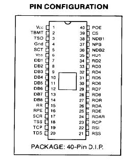
PDF of a COM2601 data sheet, which will be referenced in these remarks.
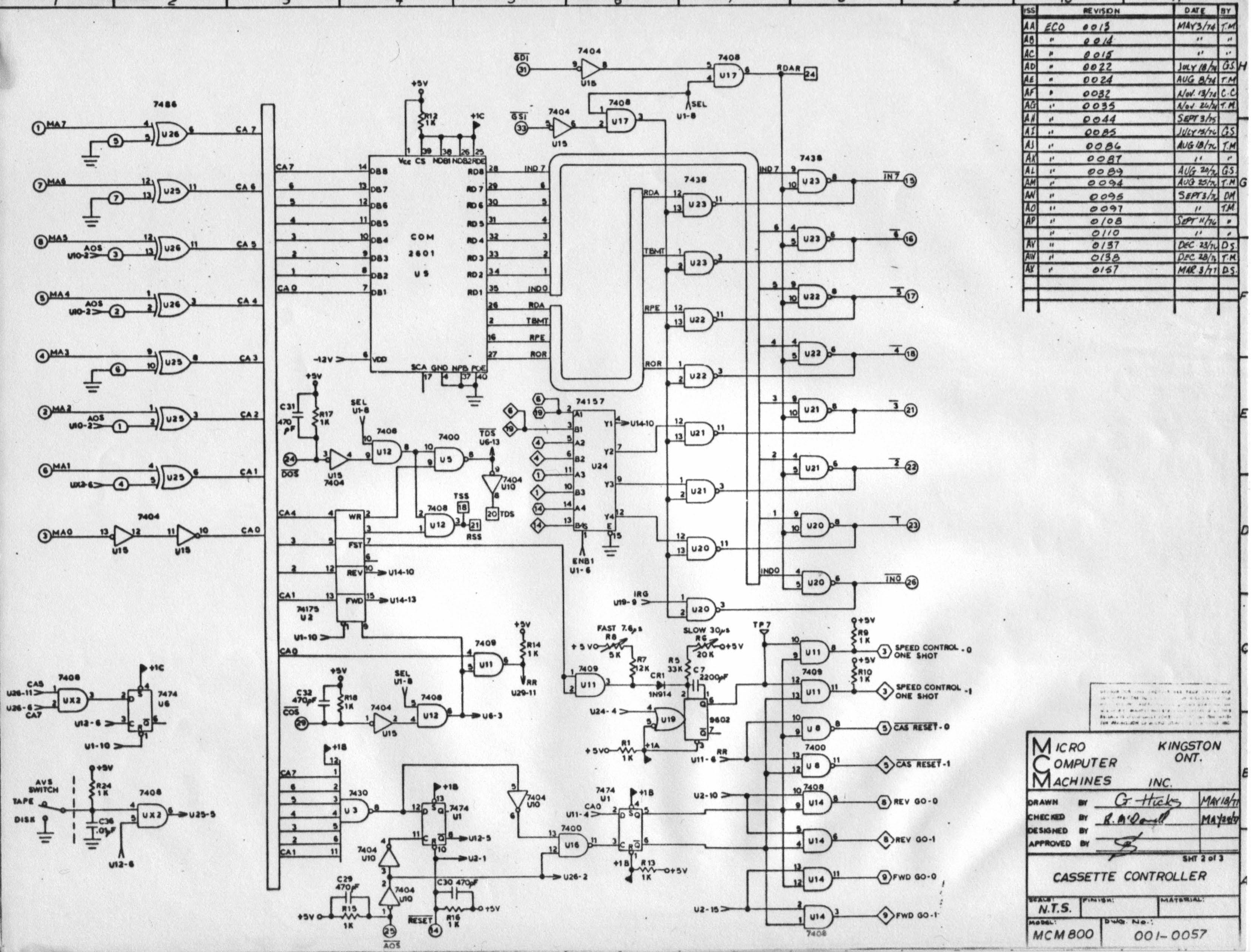
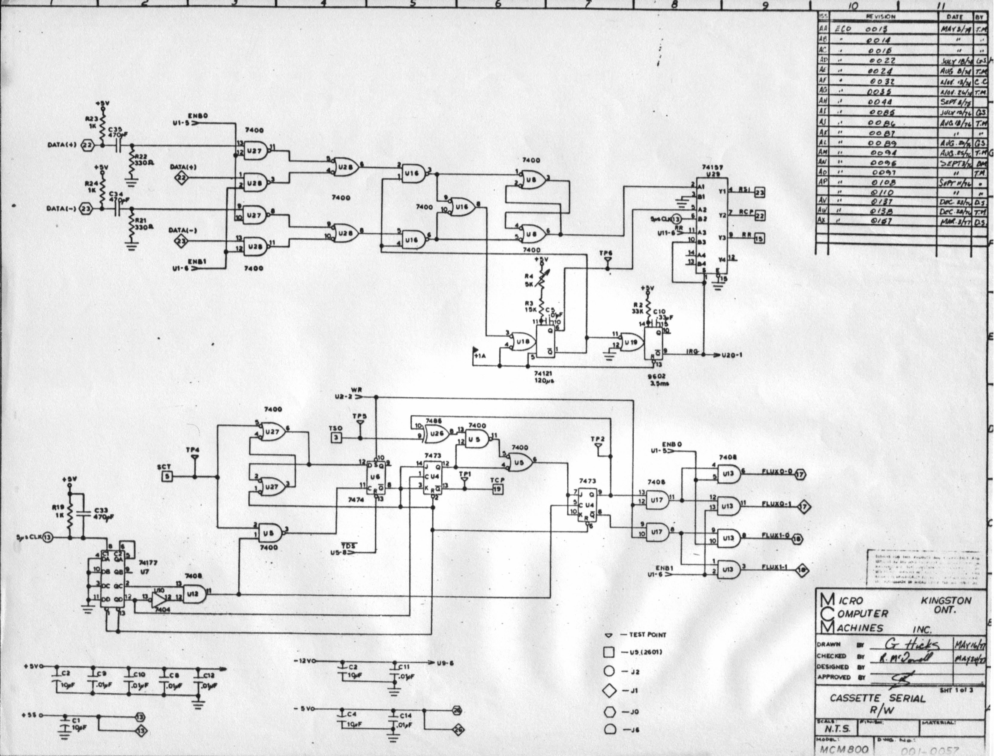
page 13 of the 18 pages of MCM800 schematics, is "Cassette controller" "001-0057, sheet 2 of 3". There's also page 14, "cassette serial r/w" "001-0057, sheet 1 of 3". There's no other schematics marked "cassette" and one other "001-0057" which is a CPU schematic.
"cassette controller" shows a COM2601 IC device. this is a USART, a synchronous or asynchronous serial reciever/transmitter. This is good news: it was a common USART device, and it identifies the bit to byte format of tape recording. Byte data in and out is identified. There's logic signals for forward and reverse, for speed control.
"cassette serial r/w" shows "data(+)" and "data(-)" clearly are tape read signals, sent through a pair of one-shots to produce read-data digital signals RSI, RCP, and RR from a 74157. These signals go to "U5(2601)" as designated on this schematic sheet.
An SMC brand COM2601 IC data sheet, identifies these three signals as on pins 22, 23, and 15 respectively, not identified on the "cassette controller" schematic (presumably they are on another schematic). Those numbers appear on the three signal lines.
"cassette serial r/w" also shows "5us CLK" (13 on J2) and "SCT" (5 from U5) and "TSO" (3 from U5) digital input signals, converted to a set of signals "flux0-0, flux0-1, flux1-0, flux1-1" to connector J1 or J0 as designated. As noted above, SCT and TSO are the as-numbered pins on the physical USART chip.
Further inspection of the various schematic may identify the source of the presumed five microsecond clock signal, but that description may be sufficient for sorting out the cassette data scheme.
MOre detailed operation of the USART may be determined by looking at the various control pins either grounded or pulled high on the COM2601 USART schematic, compared to the COM2601 data sheet.
My immediate guess about connectors J1 and J0, is that they go to either of two cassette tape decks, as these are paired signals and either one set or the other is "enabled" by other logic signals.
![[MFE250 board]](mcm800_cassette_board1.jpg)
The MFE250 tape deck photos show a small PC board with 1973 date codes on its small IC's. This board must be the MFE 250 control and data electronics, which are connected to the cassette digital hardware described in the electronics. There's one connector, 2 by 13 pins. On the MCM800 schematics, the likely corresponding connecting pins are numbered up to 26. DC power is pins 13 and 26 - typical practice is to use the end pins of a connector for power. Therefore I conclude that schematic connectors J0 and J1 are connected to either of two cassette tape decks via the connector in the PC board photo.
It does not appear that the MFE circuits are among the schematics given. I assume any MFE schematics if available, would display the MFE brand logo and identification.
It seems to me from my initial "gloss" of the schematics, The commentary from Lee Hart and Zbigniew Stachniak, plus the COM2601 data sheet I've provided, that there's enough information there to have some good ideas about how the data was recorded and read from the tapes at the bit and byte level.
It would be hard work, to restore the MFE 250 deck to operation, and reconstruct the MCM800 digital electronics, and drive them with some microcontroller - all just to recover data from the MCM tapes.
It appears that at least the data track can be accessed using ordinary audio cassette decks. The clock track is only potentialy accessable at the same time, if an audio deck supports a four-track stereo or 2-track mono head as part of an auto-reverse capability. Plus, redundant audio circuits for both sets of tracks.
So it's worthwhile, to see if the data track only can be recovered by using analog audio cassette recorders, and processing their output with some mix of simple electronic hardware plus software processing of the bit stream produced. Prior work decades ago on audio decks, suggests this possibility. From resulting playback, some rough ideas might be determined as to how to read off and decode the binary data. [But read the section below for later details which suggest the frequency and encoding may be too high for audio cassette processing.]
Herb Johnson
Oct 27 2015
In March 2016, I heard news that data from MCM800 cassettes were recovered. I got in touch with the engineer involved, Josh Bensadon. This is what Josh told me: "The drive has been reverse engineered, schematics created. The data sheet on the COM2601 was not clear on some fine details, so I bought a chip from ebay and built my own cassette interface based on the MCM800 schematic but using an LPT port interface to connect to a [IBM-compatible] PC. I'm now able to read tapes, these will go to Ziggy once I'm done. I'm also doing a write up on this system, this will also go to Ziggy once done. - Cheers, Josh"
I recieved no further information from Josh. However, in an Oct 2019 post in a vintage computing discussion group, Josh mentioned he'd worked on the tapes, drive and computer; and had further information elsewhere (location & info not provided). Apparently he ran the MFE tape deck through its TTL/logic and decoding interface, from an old "PC parallel port". Apparently he saw an 8KHz clock track and a data track with binary data at similar frequency. Web search by me, revealed two MCM computing resources, the first of course the York Museum: the second, a discussion group thread by MCM owners; links below. - Herb
- York Museum, MCM collection
reference to a MCM/70 emulator and tapes
emulator available upon request by email to the museum
tapes interpreted to "APL objects" programs in PDF form
Discussion among owners of MCM/70 systems in 2018.
Copyright © 2019 Herb Johnson