This document copyright Herbert R. Johnson 2011, update Aug 3 2011.
Check out my CCS Web page for more info on California Computer Systems.
Contact information can be found in this notice.
To return to my S-100 home page click here.
In Oct 2010 Nick Papadonis contacted me, to get some CCS source listings and manuals
to bring up his CCS system. Our discussion of that is on this linked
Web page. He also wanted to build a S-100 bus terminator card, we discuss that on this Web page. - Herb
in March 2011 Nick and I talked about his building a S-100 terminator
from scratch, Nick chose the design used by Compupro from
George Morrow. HE bought a used S-100 proto board from me to build it. - Herb
"I have the design for the Compupro active terminator on your site (I have the manual).
This is my Web page for S-100
bus termination and here's
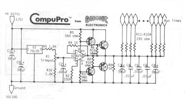
a schematic for the Compupro/Morrow terminator.
"I was going to order all the parts from Jameco, but realized I didn't have a card to put them on. The tough part was the resistors near the card edge. John Monahan from s100computers.com suggested I use resistor packs instead."
"John also commented on the CompuPro Active Terminator schematic vs pic (attached) I sent him. The two voltage regulators at Q4 and Q3 were the only parts I couldn't find. He suggested they were 7805's, but didn't understand why the board had two voltage regulators vs schematic having one."
Q3 and Q4 are transistors, not voltage regulators. Part numbers are listed on my Web page. "Q3 D44CX, Q4 D45CX" my page says, but most any PNP and NPN power transistor in a TO-220 case would do, that "runs" at a voltage well above 20 volts. The full designation of the transistors is probably "2SD44CX" or something like that.
Mid-April: "Still waiting for a couple more parts for the terminator, but I stripped it of all the old components. Thanks to Edsyn Soldapult II desoldering tool!"
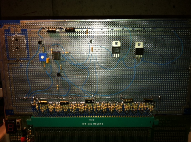
By June Nick said: "It works! I have parts to build another and I may do so. They keys to this is getting the resistors to a common bus. I had to cut some traces on the Proto board to facilitate this. Once that was complete it was pretty easy. Waiting for the parts took the most time. The final test is adjusting the pot so 2.6v is across C3. I used a 2K trimpot and I used a TIP122 and TIP42C for Q3 and Q4. C4, C5, C6 were kept 39uF to match the original schematic in the manual (vs your web page). [Says Herb: "You need a couple of .01uF caps to bypass high frequencies.]
Here's a photo of the board Nick built.
In August 2011, Nick writes: "Following up on the terminator. I tested it tonight in the NorthStar Horizon with a ZPU card, Vector Graphics 64K DRAM and N* FDC. I ran [a memory test program] MEMR.COM without the terminator installed, and the memory test failed in the upper address space. I installed the terminator and the memory test passed at least three times. I'm going to leave the terminator in. Looks like it's doing it's job. I may purchase an extra proto board from you and build another soon."
Nick previously asked this: "I was checking this out a bit more tonight. Do you have any suggestions for voltage levels to watch? I'm seeing slightly different voltages when probing the bus without and then with the terminator (on signal lines). Without the terminator I'm seeing 0, ~1V, ~4.85V. With the terminator it's 0, ~2.0, ~3.0. Weird, perhaps it's wired wrong?"
I explained it this way:
"Zero volts" should mean the line is driven low, it's more likely a few tenths. "2-3 volts" suggests the line is not driven high or low, that's the terminator's voltage level. A "high" voltage should be above 4 volts or so, it won't be Vcc (5V) due to voltage drops of various sorts. On an oscilloscope, you'll likely see some high/low/3V activity on a number of lines.
The Web pages I have on the S-100 bus and bus termination are reasonably informative. There's a lot of discussion there, maybe too much. Look at the Compupro manual exerpt I quote on the page above. But you'd have to tell me which S-100 lines you are looking at for which voltage, for me to guess if there's a problem.
Most of the lines of the S-100 bus are driven by a TTL output or a tri-stated output, and have one or more TTL "inputs" - like the address lines, every board uses some of the address lines. The purpose of the "active termination" is to hold these lines to a reasonable voltage level, and to provide a bit of noise reduction. The tri-stated lines particularly need termination when they are "floating" when the drivers are "disabled". There's also an argument for active termination versus simply "passive" resistors, which would draw more current, that's made in the Compupro discussion I quote above.
Keep in mind, a very few of the S-100 lines are "open collector". They are driven by a transistor with a grounded emitter and the collector is tied directly to the s-100 line. At the "far end" of the line, in principle, is a "pull up" resistor. ALL the devices on that particular line are "driven" by one (possibly more than one) transistor - but only ONE pull-up is needed, but it IS needed, somewhere. Those few lines may read differently than the other lines. (I don't think there's harm in adding an active terminator line as well - I'd have to think about that, see if others did that with their terminators.)
Of course, a few lines are either grounds, or DC power and those lines should NOT be "terminated".
YOu can probably download schematics for S-100 active terminator cards or motherboards, see what they did. But in the end, you have a S-100 CPU board that "drives" your boards, you can look at its schematic to see which lines are actively "driven". Same with your other boards, a few of them "drive" lines beyond the data outputs (inputs to the CPU board).
So check your wiring, versus the CPU board you are using, to see what lines are what. The point of the terminator is to offer a constant voltage (whatever yours turned out to be, 3V or so) at each line *through individual series resistors*. So you'll see some variation at the actual bus lines, depending on their "active" state and how much current they draw through the series resistor. More current, larger voltage drop. But at "no" activity, an open line, there's little current and the voltage is close to the output of the transistor pair. - Herb
Herb Johnson
Copyright © 2011 Herb JohnsonS-100 terminator
in use
voltage levels
New Jersey, USA
here is how to email @ me