![[Zilog Z80 system]](zilog_aft1.jpg)
This page last updated Aug 14 2023. Copyright 2023 Herb Johnson This page is a series of Web pages about restoring vintage microcomputers; Check my restoration home page for more. To email me or to order, see see my ordering Web page for my email addresses.
![[Zilog Z80 system before cleaning]](zilog_bef1.jpg)
The hardware details of my two systems and additional boards are described below. Through the years, I've been contacted by other owners of MCZ systems; details are below. Please contact me about your Zilog systems. - Herb Johnson
A few years ago, I picked up two of these Zilog Z80 MCZ 1/20 development systems at a hamfest (I think). In Aug 2009 I did some review and cleanup of them. These were sold by Zilog in the late 1970's for Z80 development, based on their own bus architecture. Check other Web sites for the history of Zilog and their flagship Z80 processor.
It looks like this system used hard-sectored diskettes - that's consistent with the lack of an FDC chip on the boards, and the date when these boards were first laid out (copyright of circuit board 1975-76, before FDC chips existed). Another system owner, Peter Hill, confirms this. In 2021 I was
contacted by Les Bird who recently restored two 1/20 systems and created images from
OS disks; details are described here on on his site. I also have discussions about some
of the EPROM and bipolar PROMs in use on these boards. And a source provided some
reverse engineered schematics. This page has some notes about other sites. about
these systems. - Herb
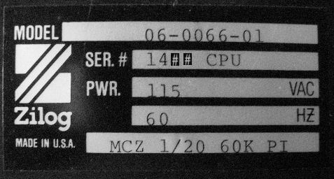
The photos in the Introduction are of the system #10XX. The label on the CABINET identifies it as a 60K system "MCZ 1/20 model 06-0066-01". That does not mean the current configuration or card set matches that model.
![[Zilog Z80 MCB]](zilog_mcb1.jpg) Zilog MCB (Memory Computer Boot) board 09-0013-09 rev F. Stamped June or January 1979 but board copyright is 1976. RAM chips are HM4716A-3 from 1978 (16Kbytes total). ROMs are 2708's, three at 1Kbytes each. Zilog chips include the Z80, CTC, PIO. AMD chip is AM9551. The parts with labels "0053" are bipolar PROMs to address memory.
Zilog MCB (Memory Computer Boot) board 09-0013-09 rev F. Stamped June or January 1979 but board copyright is 1976. RAM chips are HM4716A-3 from 1978 (16Kbytes total). ROMs are 2708's, three at 1Kbytes each. Zilog chips include the Z80, CTC, PIO. AMD chip is AM9551. The parts with labels "0053" are bipolar PROMs to address memory.
The circular part in the lower right, is an inductor for circuits to produce +12v and -10v for RS-232 serial, and +12V, -5V for DRAM/ROM. Chips A37 and A41 are AM1488 and AM1489 respectively, RS-232 (EIA) serial interface chips, with traces down to the edge connector. Open pins around the PIO, are likely intended to be wired to the open pins and IC positions on the lower left of the card. the edge connector has pins wired to postions marked Z1 to Z21, which are not connected elsewhere. This is probably where one would wire the PIO or PIO interface chips.
![[Zilog Z80 MDC 2]](zilog_mdc1.jpg) Zilog MDC 2 (Memory Disk Controller) board, 09-0015-07C (c)1977, made in July 1979. Chips have date codes of 1977 and 1978. RAM is Hatichi HM4716A-3 from 1978. the large chip is Zilog but not identifiable. This board also has a circular device, an inductor or transfomer, to create an additional voltage for the DRAMs.
Zilog MDC 2 (Memory Disk Controller) board, 09-0015-07C (c)1977, made in July 1979. Chips have date codes of 1977 and 1978. RAM is Hatichi HM4716A-3 from 1978. the large chip is Zilog but not identifiable. This board also has a circular device, an inductor or transfomer, to create an additional voltage for the DRAMs.
![[Zilog Z80 interface]](zilog_if1.jpg) Zilog interface board rev A. has a Z8001A CS "SEQ CPU". Chip date coes are 1979 80 81, the RAMs are Fairchild MB8264-20 from early 1981: 32 of them suggests 256K bytes. Ther are not many connections to the edge connector; there are two IDC (flatcable) connectors at top, 26 pin and 60 pin.
Zilog interface board rev A. has a Z8001A CS "SEQ CPU". Chip date coes are 1979 80 81, the RAMs are Fairchild MB8264-20 from early 1981: 32 of them suggests 256K bytes. Ther are not many connections to the edge connector; there are two IDC (flatcable) connectors at top, 26 pin and 60 pin.
![[Zilog Z80 motherboard]](zilog_mb1.jpg) Zilog motherboard or backplane, 09-0018, etch 10-0018 rev H, from 1977. The backplane connectors consist of 122 pins, 61 pins per board side. The backplane is not a "bus", in that each backplane connector is wired for a specific board. On the boards, Pin 1 is rightmost on the component side when holding the board with edge connector down; Pin 62 is leftmost on the non-component side. So pins 1 and 62 are across from each other on the backplane board socket or through the PC board.
Zilog motherboard or backplane, 09-0018, etch 10-0018 rev H, from 1977. The backplane connectors consist of 122 pins, 61 pins per board side. The backplane is not a "bus", in that each backplane connector is wired for a specific board. On the boards, Pin 1 is rightmost on the component side when holding the board with edge connector down; Pin 62 is leftmost on the non-component side. So pins 1 and 62 are across from each other on the backplane board socket or through the PC board.
![[Shugart 800]](zilog_drive1.jpg) The floppy drive is a Shugart 800-2, with a 25102-4 card by part number. Parts date from 1978.
The floppy drive is a Shugart 800-2, with a 25102-4 card by part number. Parts date from 1978.
The MDC 2 board clearly has a Z80 PIO as the only 40-pin chip. This board is a rev C. The MCB board for this system, has additional chips added on the left side of the board. You can see the wiring on the back of the board as imaged here for those chips. The MCB board on the other system is not wired or chipped as described here. Wiring of this sort is entirely normal for the era and is called "white-wiring" because most often the wire used is white wire-wrap wire. Peter Hill comments on this wiring in his notes. I pulled from the ZDS 1/25 Hardware User's Manual, some documents showing board-slot locations and cabling. Each ZDS board has its own slot, and there's slots
designated for optional boards, such as the PROM programming boards.
In July 2021, Les Bird contacted me (see elsewhere on this Web page) and also made note of the ZDS board order in his system.His seems different than mine. Les explained to me: "You said you used the manual from the MCZ 1/25 to get your board ordering. The MCZ 1/25 is the rack mount version of the MCZ computer. You have the 1/20 which is the table top version. I think the ordering is different between them but not sure."
When I'm able to review my 1/20 chassis, I'll see if I can follow the wiring from the floppy drive and see which slot it goes to - that is different between Les's configuration and the 1/25 documents. And Les has 1/20 docs! "The board order for the MCZ 1/20 can be found on page 18 of the MCZ-1_20_25_Hardware_Users_Manual.pdf" - Herb
In 2009-10 I was contacted by Peter Hill about his system that he's trying to return to service. - Herb
"I was asking for sources for a memory de-code PROM [when previously
posting in sci.electronics.repair about my Zilog development system]. [Here's what I posted:]
"I've got a Zilog MCZ 1/05 development system. A memory decode PROM on the 12/48K memory card (fitted with max 3x16K banks other 16k for 64k is on CPU card) has blown and was running hot. About 10 years ago I made a decoder from TTL but it's 5 chips on a
board attached to the socket by a flying lead. I've tried to
reconfigure the memory so it bank switches the monitor EPROM for
memory on the CPU card thus reducing the decode to a simple A14 and
A15 bank select on the 48k card but hit a race [timing] problem.
"I'd like something that can mounted on the socket instead of a card. Any ideas on lower chip count replacement? Even PIC or amtel if it can decode the 5 input lines and select the memory bank in 20ns. [He got supporting responses to create new PROMs in reply.]
"[My] conversion to CP/M required a new memory decode prom for MDC-2 (Memory
Disc Controller 2) with I think (and hope) 6Fh in byte 10. And some
mods on the MCB CPU/boot card to allow switching of the 4x1K boot
proms out of the memory map at 0000h.
The MDC memory decode PROM is where my problem lies, it's burnt out.
20 years ago I made a decoder from TTL that plugged into the PROM
socket. 10 years ago I got clever but not clever enough by half. I
tried to re-arrange the mapping so first 16K was on MCB and other 3
16K banks on MDC, then I could ignore A12-13 and just decode on
A14-15+RFSH. I got it wrong somewhere, so I gave up and tried to
reverse all the changes I had made. That failed too, so I don't have a
working system. I've checked decode logic by plugging into Tatung
Einstein user port and it seems correct, which means I'm looking for a
link on a jumper header or track break that's wrong. - Peter Hill
See my notes below about PROMS, for more info.
Peter gave me notes about Zilog systems, including comments on my systems. The notes are below.
Ralf-Peter Nerlich of Germany used the Zilog development systems in the 1970's. Here's his description to me of those systems. He has a Web site at this link about RIO-OS and Zilog brand development systems. - Herb
"There are two families of Zilog's development systems - MCZ and ZDS.
MCZ systems are for software development and automation solutions.
Several models are exists, for "desktop" use (like your 1/20 model)
or rack mount systems. The high level model 1/35 even has a harddisc.
"The ZDS series are systems for soft- and hardware development.
They contain additional components to test z80 user hardware
(RAM & ROM emulators for user hardware, incircuit Z80-CPU-emulator,
bus analyzer).
"Both system families use Zilog's own Z80-RIO Operating System,
but with a different ROM resident Kernel.
The disc format is Zilog proprietary; 8" hardsector discs, single sided,
32 sectors, 77 tracks, 132 Bytes per sector.
(128 data bytes and 4 pointerbytes for linking physical sectors to
logical files at OS level)
"You can use any serial rs232 terminal as a console. The interface
is situated on the MCB-Board. Optionally alterable to 20mA current loop.
110 to 19200 Baud.
"Some development software is availabel for RIO:
Z80 Assembler & Linker, Z8 & Z8000 cross software packages,
PLZ, FORTRAN, COBOL compilers, BASIC. No "office-type" software.
"For MCZ especially, a CP/M 2.2 implementation exits, using a later
revision of the MCB-Board or a modified older MCB-Board."
- Ralf-Peter
The back plane is specifically wired for each card location.
The "Transformer" on the MCB card is an inductor for +12v, -10V and
-5V. It supplies +12v and -10v for RS232 and +12V, -5V for DRAM/ROM.
There is no on board programming function.
If you have 1/2K or 1K rom (one chip) then it's just monitor, 3K rom
means it can use pre formatted 32 sector Floppy. Card traces have to
be cut and links made depending on ROM type.
4K (4K drams) or 16K (16K drams) at 1000h or 4000h depending on
monitor, have to mess with soldered links on J3 header to set base.
The PIO card's wire wrap is a huge mess even when done by Zilog for Tally
printer. Otherwise it's DIY for 2 8 bit ports.
The MDC [disk controller] is FM only for 32 hard sector or soft sector discs. Huge slow down
on 26 sector soft sector discs, the drives go clank, clank, clank as
head is repeatedly loaded and unloaded. I was unable to work out if
this was due to interleave or some other reason but it was damn
annoying. I can't remember if this was the UCSD Pascal or CPM but RIO
was hard sector.
Floppy is fully driven under Z80 instruction uses PIO for floppy
control and LS299 for serial encode/decode. FDC chips don't work any
differently, just use VLSI and usually can do MFM in addition to FM.
It's quite instructive on how FDC's work. As timing is critical it
disables video card during read/write if memory mapped video card is
present.
MDC Ram can be either 12k (3 banks of 4K) or 48K (3 x 16K), size is
set by wiring of J1. It's normally located from 2000h for 4k dram, 16K
dram 1 bank is at 1000-3FFFh and then 8000h to 08FFFh, next bank 9000h
to 0CFFFh and last bank from 0D000h to 0FFFFh. 4K of last bank isn't
mapped for RIO. This decoding/mapping is controlled by a 32byte PROM
that decodes A12-A15 and RFSH, to output RAS0-2 and CAS (only 4
outputs used), RAS0-2 are RAS lines for each ram bank. For CPM this
PROM is changed for one that maps the remaining 4K segment of bank 3
into 0000h and there are white wire mods to the MCB board.
- Peter Hill
In early July 2021, Les Bird (of the Heath SEBHC group for H8, H89 and related Heathkit computers) contacted me as follows. He's gathered up a LOT of MZC materials and disk images. - Herb
I’ve recently acquired 2 Zilog MCZ computers on eBay. The name plates on the back are: PDS-MOD-5 and MCZ 1/20 60K PI. The PDS MOD 5 is the one that came with the Z8000 dev board. Between the two I got one working. I programmed on these machines back in the early 80s, it was my first job out of high school, so I was pretty excited to get one in my hands. I had several floppy disks from back then so I wanted to create software disk images of them for archival purposes. My progress can be found
[on the sebhc github site for the MCZ]
... along with lots of useful info for anyone else that needs to thinker around with these machines. I tried to document as much as I could. Additionally I bought up as much of the documentation I could find on eBay including hardware user’s manuals for the MCB CPU board and the MDC floppy disk controller board. All of it has been scanned and added to the above link. The code samples I posted [at github] are used in my MCZIMAGER program that runs on the MCZ computer in the RIO OS [to produce disk images}, so all that stuff is working.
Maybe you can find it useful, if you still have your Zilog computer.
[With MCZIMAGER]I managed to create complete disk images of all the software I had that could that could be useful including RIO OS boot disks. Unfortunately to use these you need a bootable system, which kind of defeats the purpose of posting boot disks. I’m working to try and find a solution to this problem. Ideally it would be great if you could punch in the imager program into the MCZ debug console and then run it without a disk but for some reason this does not work as I expected. So for now the imager needs to run in RIO OS.
[Here's what happened so far as I tried to write an internal disk imager.] I [wrote] software to read disk images track by track and send them over the serial port to a host PC, and vice-versa. I posted several disk images of the RIO OS on the GitHub page. The problem I’m having now is that in order for this to work on a system with no boot disk, you gotta be able to “upload” code to a debug console without an OS, and then have the code run and receive the disk data and write it to a disk. Right now, my system requires the RIO OS. Because, when I upload the byte code to the MCZ debug console and execute it, it hits a breakpoint somewhere in the PROM code and halts.
I’m trying to figure this out [in early July]. Something is not getting initialized when powering the system that my code is relying on (my guess). At the moment I’m writing some small test programs to type in to the debug console to see where it breaks. Will keep you posted. Not sure if any of this is useful to you but maybe it could be useful to someone else. Feel free to spread the word. - Les Bird
I got the “cold” boot method to work. This is fantastic because now anyone with a MCZ computer but with no software can upload the imager to the debug console and then upload a bootable disk image. Took a lot of research and debugging but the issues were (1) I had to specify a user stack in my Z80 code (LD SP,xxxx), (2) I had to set register I to 13H (weird, not sure why but found this in the documentation) and (3) had to make sure interrupts were enabled (EI) when the program starts.
I was able to upload the MCZIMAGER [Z80 software] to the MCZ computer. My host software will do this by typing in the hex code for you and then it auto jumps to the org address to run it. Then I was able to send a RIO OS bootable image to the MCZ computer and when it was done I was able to boot the OS from the created disk.
I’m now going to clean up my host software and build PC and Linux versions and post them on my website along with the updated MCZIMAGER.S source code. - Les Bird
One other thing, the board positions in the slot cage are important. If they are not in the correct slots the system will not work. Slot J1 is the card slot that is closest to the disk drives. So for a working system [like mine] you want MDC in J5 and MCB in J8. I think I saw a picture of one of your systems with the cards in the wrong slot. Just an FYI. The board order for the MCZ 1/20 can be found on page 18 of the MCZ-1_20_25_Hardware_Users_Manual.pdf - Les Bird
Herb says: As for writing disks "cold". I know from my own experiences, how hard it can be to operate a Z80 system without use of its supporting OS. CP/M made this stuff simple, and MS-DOS was reworked CP/M; so this kind of work is becomming "lost art" from lack of opportunity. I suggested to Les Bird at the time, I thought it reasonable to continue to try to run a stand-alone program to recieve and reproduce a disk image. For instance, Dave Dunfield's collection of "imagedisk" utilities and disk images, includes what he calls "transfer utilities" to such systems as the Northstar hard-sectored Z80 S-100 system. As Les explained, he found some hardware software setup issues.
As for boards in slots. Thanks for the head's up that the order may vary from model to model. I'll follow
the cables on my chassis to confirm where the floppy and CPU/serial cables go to which slot.
So as of early July 2021, Les Bird is able to run MCZ OS and has programs to communicate with it from a hosting "OS-X" (Apple Mac kind-of Unix) system. That software created the disk images he has made available. His years of work with H89's and H8's continues to pay off. The Z80-side source is available; soon the C++ sources on the PC side will be too. - Herb Johnson
One issue with these systems, is their design's use of fusible link bipolar PROMS to select addresses. In the mid-1970's, a number of these small programmable devices were introduced. In this design, they provide high-speed decoding of the address bits from a microprocessor. Because of size and speed, they can't easily be replaced with TTL logic chips, diodes, etc. But they fell out of favor and use by the 1990's, and even if chips can be found they are not programmable on "EPROM" type programmers.
Peter Hill described these to me in 2010: "It's a Harris 7603 Bipolar tri-state 32x8bit PROM.
Here's a data sheet on that device." Peter describes the addressing options for
the PROM on the CPU board, in this text document. My CPU board uses an MMI
brand 6306-1J chip. Peter's work on these PROMs is described above.
note: I'm generally interested in old bipolar PROMS, which were used in many early microcomputers amd minicomputers of the 1970's.
For more information about bipolar fusable PROMS in vintage computers, check this linked Web page where I show several examples and how-to-read and program them.
2708 UV EPROMS
A similar issue exists with the program UV-erasable PROMS on the Zilog system. They are 2708 1K X 8 PROMS, made by various companies in the 1970's. These (and the earlier 1702) used multiple voltages to operate, namely 5V, -5V, +12V. They fell out of favor, over later single-voltage UV EPROMS, and later by electrically erasable PROMS. Most of the EPROM programmers developed and sold in the 1980's through today, cannot read or write 2708's and earlier PROMS. But a number of vintage computers - notably S-100 systems - included boards to program these devices. And a number of early "how to use microprocessors" books included 2708 programmer designs. There's even a few surviving VERY vintage programming systems for the 2708.
So my choice was to build a 2708 reader/programmers, or revive a S-100 programming card. Here's a Web link to my S-100 Web pages where I list S-100 manufacturers, some have 2708 programming cards (Cromemco for instance). But in 2013, I obtained
an old-enough EPROM programmer which supported 2708's, and I read off one
set of CPU EPROMs- Herb
In April 2019, bitsavers.org has assembled source for similar ZDS PROMs.
CHeck this ZIP file on their site.
An anonomous source contacted me in Nov 2011 as follows below. - Herb
Many years ago in 1983 I worked as an Electrical Engineer for a large
company. We had dozens of ZDS 1/40's used for development. The 1/40
was a 4MHz version of the 1/20. Myself and another engineer decided to
take the schematics of the 1/40 (from the Zilog manuals) and update them
and create a single board version. We wanted to be able to have our own
ZDS 1/40 system at home to do experimenting and we ended up doing
several Z80 projects with the boards (we each had one). It was a big
wire-wrap board connected to a pod, two 8" Shugart disks, a serial
connector breakout board with two DB25's, a power supply, and a dumb
terminal.
The schematic is 100% compatible with the original ZDS 1/40 unit. Note,
CONN B was connected to a PCB from an existing system that we used to
give us a connection to two DB25 connectors for the serial ports. These
connection points could be replaced with DB9 connectors. It runs the
same software, etc as the standard ZDS 1/40. At the time, we also
convinced Zilog to give us all the source code for the ZDS 1/40 system
since we thought we would have the units long after Zilog gave up
support for them. I had the code on 8" hard sector disks and I
transferred it to 5-1/4" disks. Several basement floods, and a lot of
time, have apparently made them disappear so, unfortunately, I no longer
have the source code. However I do still have the schematics for the
wire-wrap we did.
The schematics were hand drawn on velum by myself and another engineer
in 1983. They are a copy of the ZDS 1/40 schematics (and if I remember
correctly, some updates to simplify using better circa 1983 parts) that
consolidated all of the boards into one. The schematics have a
connector that ties to the ribbon of the standard user pod (CONN A), and
a connector for the serial ports (CONN B).
Looking at it now, the whole thing could be easily be put in an Altera
or Xilinx FPGA using current external static memory devices in place of
the dynamic 64KB memory, the CPU 2KB static memory, and the Trace 8KB
static memory.
The schematic would be a good starting point to build a new version of
the ZDS 1/40 emulator by integrating all of the logic in an Altera or
Xilinx FPGA, removing the serial ports, removing the Floppy controller
logic, and adding an Ethernet port (all inside the FPGA). The Z80
itself is availabel as IP from CAST Inc. for the Altera Cyclone series
FPGA and can run at a speed of up to 82MHz. Essentially, the whole
emulator could be upgraded significantly. The pod and the hybrid Z80 on
the end of the Z80 in circuit emulator pod cable looks like it could
also be easily duplicated in an FPGA. It would be a very interesting
contrast to see such a re-designed system sitting side-by-side with the
original ZDS 1/40.
The scanned drawings are PDF's at 600 dpi and grey scale, 11"X17", 22 pages. - End
The 22 pages of schematics are available from me by request, as 12MB PDF file.
They are similar but not identical to schematics in the ZDS 1/25 and 1/40 hardware manuals. Links to those PDFed manuals are given in the "Other Resources" below. - Herb
In July 2023, Poul-Henning Kamp of the datamuseum.dk contacted me about some MCZ disks and documents they
recovered. "The five 8" MCZ floppy disks [now imaged as binary disk-image files of 136 byte sectors] are now
in our BitArchive.
Any other Zilog related artifacts we digitize later will also appear on that page. [He noted that
at least one disk, was formatted with a track 78 but the track had no data.]
I also put the two small [Kyroflux] Python scripts I used to extract the data
from the KryoFlux stream files on our Github page
Thanks for the help! - Poul-Henning"
Ralf-Peter Nerlich contacted me in July 2010. He's worked on a presentation about his MCZ experiences in German. It was on the home.arcor.de domain at the time, under rp.nerlich. As of 2021 it's gone. Thanks to Peter Hill for comments and corrections to that document, and other assistance and discussion with about PROMs. In 2021, I'll have to see if I have that document or can find Nerlich on the Web.
Documentation for the MCZ may be found on
Maben's archives in the Zilog/Brochure section These seem to be 1/25 or 1/40 systems. They are slightly different from each other.
bitsavers.org has Zilog MCZ-1 documents and ROMS as PDFs and sources.
dyndns.org: I was contacted in Oct 2016, to let me know the dyndns.org content and site was available again on a different host. The dyndns.org archive many ZDS manuals. It also includes work on reverse engineering a ZDS 1/25 or 1/30 or 1/40 system. In Oct 2016 I was informed: "I scanned the manuals by myself [in 2003]. I don't know if Wolfgang Kainz-Huber knows where he stored the Floppydisks for the ZDS or the manuals but you can get in contact with him. As the document belong to the ZDS they may be identical [to docs scanned elsewhere]. [But the Epson Perfection 1640SU scanner I used, has] a plastic stripe for the paper and [produced a scratch so the] scratch was scanned too. So on a lot of old scans from me you'll see a black stroke maybe 3cm from the right side [in black or rainbow-colored]. The Zilog MCZ 1/30 and Zilog MCZ 1/05 were donated to the ComputerMuseum–Muenchen (Munich, Germany) "
Yunlin University of Science and Technology Museum in Tiawan seems to have "MCZ-1/20,25, MCB board series, hardware user's manual" "QA76.8.Z54 M35 1977". Apparently there were "clones" or near copies of both the Zilog systems and its DOS, produced in Eastern Europe. These included the EAW P8000, Robotron A5120 and others. They ran the UDOS operating system. These UDOS systems still exist today in museums and private hobby collections. Look at this Robotron Web and UDOS site for an example.
Apparently a computing museum in the UK has some Zilog diskettes.
The linked Web page shows three Zilog diskettes at the Centre for Computing History in Cambridge as "reference ID of CH12164". I had word in April 2019, that the
museum received a Zilog ZDS system, and may be working on their disks with that system
or with other data-recovery hardware. - Herb
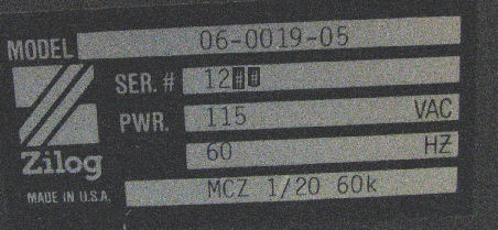
Copyright © 2023 Herb Johnson![[Zilog Z80 system #2]](zilog_sys2.jpg) This system #12XX has the same board set as the first, in the same slots, and two Shugart 800 drives. The label on the CABINET identifies it as a 60K system "MCZ 1/20 model 06-0019-01". That does not mean the current configuration or card set matches that model.
Labels and markings in the system give dates of use for 1979 and 1980. The motherboard has a label: MCZ REV H BACKPLANE MOD???? For Video
This system #12XX has the same board set as the first, in the same slots, and two Shugart 800 drives. The label on the CABINET identifies it as a 60K system "MCZ 1/20 model 06-0019-01". That does not mean the current configuration or card set matches that model.
Labels and markings in the system give dates of use for 1979 and 1980. The motherboard has a label: MCZ REV H BACKPLANE MOD???? For Video
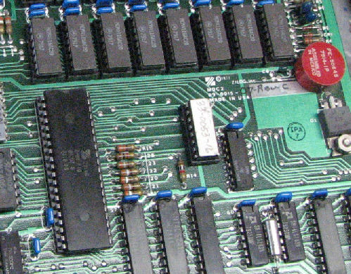
![[Zilog Z80 MCB for system #2]](zilog_lab2_3.jpg) The parts with labels "0053" are bipolar PROMs to address memory. The three program PROMS are 2708's. In 2013, I read off the three EPROMS, here's the ZIP file with hex records and a very crude disassembly - you can do better!;)
The parts with labels "0053" are bipolar PROMs to address memory. The three program PROMS are 2708's. In 2013, I read off the three EPROMS, here's the ZIP file with hex records and a very crude disassembly - you can do better!;)
Cards and slots and cables
additional MCZ cards
In 2012 I acquired this PPB/16 card, labeld "PROM Programmer 2716-MCS", 09-0069-01 rev C. Chips on the card are dates up to late 1979 and one early 1980 chip. As with other cards, the grey circular device on the board, is a transformer for
an inverter to generate programming voltages. Two Z80 PIO chips provide the interface to the
three sockets. Software and hardware support programming 2716; and bipolar PROMs 82S27, 82S181, 82S131. From left to right at the top of the board, the sockets are labeled "BI POLAR BI POLAR E PROM". Here's the slot pinouts, for one of the PROM programming boards, 09-0031; This and other PROM boards, may each have the same pinouts.
In Oct 2013 I acquired this PPB card, 09-0019-02c. It's a 2708/2716 PROM programming board. Date codes on the chips suggest construction in late 1977. Software and hardware support programming 2704 and 2708; and bipolar PROMS 7610, 7611, 7620, 7621, 7640, 7641.One Z80 PIO chip seems to handle the three sockets.
In Mar 2015 I acquired another MDC card, a
48K DRAM card.
In Mar 2015 I acquired this SIB card, with
four 8251 UARTs and three Z80 CTC timers.
Zilog system in UK, address PROM issues
Zilog in Germany
Peter Hill's notes about Zilog systems
Les Bird and two MCZ systems
Disks from images "cold"
Some time later ...
boards in slots
Les Bird's system slots for PDS-MOD-5 and MCZ 1/20 60K PI
disk drives
J1	option board
J2	option board
J3	option board
J4	SIB - multiport serial 8251's (optional)
J5	MDC - floppy controller w/48K RAM
J6	RMB/PMB
J7	HDI
J8	MCB - Memory Computer Boot, CPU board with ROMS RAM 8251
J9	PPB - PROM programming board (optional)
side of cabinet
Herb replies
Bipolar PROMs
Reverse engineered schematics
Brief notes on other sites with MCZ content
Herb Johnson
New Jersey, USA
follow this link to email @ me