![[rev F 1802 M/S Card]](build/cpu_power.jpg)
Last Updated May 30 2016. Edited by Herb Johnson, (c) Herb Johnson, except for content written by others. homepage for 1802 ELF Membership Card.
In January 2014, I built a rev F version of the 1802 Membership Card, as a show-and-tell for another Web page. The results provide some photos and comments about assembling any 1802 Membership Card. I also made modifications, and added a ROM monitor and serial interface. These mods may be of interest to owners of Revision F or earlier M/S cards. Look at that linked Web page for details.
I also debugged the IDIOT ROM monitor code for the first time for the M/S card, debugged issues of baud rates on a software UART, and debugged a serial interface circuit. Those notes were moved to this Web page in May 2016.
Subesequent versions of the 1802 Membership Card support both ROM and RAM, include a serial interface, have improved address circuits. Go to the Home page of the 1802 Membership Card to access the support page for the version of interest to you.
I assembled and tested and debugged the IDIOT ROM monitor (inspired by RCA's UT4 monitor). IDIOT was originally used on another 1802 card, the "BASYS board", and the source code needed some additions based on other BASYS software (Tiny BASIC). A useful and correct baud rate, required the M/S card to run at full speed; both a 1.77Mhz and a 2.0Mhz ceramic resonator were tested. These notes may be informative, if you are having trouble running IDIOT or some other ROM monitor on the M/S card.
The 1802 Membership Card is a very open and simple platform for the 1802 microprocessor, much like the ELF was decades ago. Work like this has contributed to the evolution of the 1802 M/S Card, and to the variety of ways owners have adapted and assembled the card. - Herb Johnson, May 2016.
As this was first use of the recovered IDIOT monitor code, there were working issues. Also, procedures were not yet established for setting up the Membership Card's variable CPU clock to operate a software UART as in the IDIOT monitor. And the serial interface was a breadboard and not an assembled circuit. These were resolved as discussed below. - Herb
![[PROM]](build/prom_burn.jpg)
screenshot, PROM burning software IDIOT monitor written to 27C256 UV EPROM
code changed to use EF3 not EF4 for input.
Attempted to run ROM monitor with simple RAM program "long branch to 8000H - C0 80 00".
OScilloscope shows interface produced reasonable 0/5V signal to EF3 input from RS-232 transmit, at various baud rates.
But program failed to respond with changes to Q. Oscilloscope shows something running but hard to determine "what".
Possible problem: IDIOT monitor may be looking for "active high" serial, not "active low".
Needed to modify IDIOT code to establish input and output are active low (inverted).
Here's the resulting IDIOT code, using IF/ELSE/ENDI statements and A18 assembler. These are now in the IDIOT source code. Example:
			      QHI	EQU	0		; 0 => Q active low
					....
   0000                  IF QHI
                        	SEQ			;    SET Q IF BIT=1
                        	LSKP			;    RESET Q IF BIT=0
                        OUTBIT	REQ
                         ELSE
   815f   7a            	REQ			;    RESET Q IF BIT=1
   8160   c8            	LSKP			;    SET Q IF BIT=0
   8161   7b            OUTBIT	SEQ
                         ENDI
progress, briefly saw IDIOT prompt, but there was likely problem with baud rate or ASCII stream.
In previous tests, I ran the clock too SLOW, at near the lowest clock rate. When I added the board extender, I had better access to the potentiometer to speed up the clock. I tuned it to the FASTEST clock rate. That did not produce a correct echo of correct characters. Next I'll "tune" to run at 1.8MHz, the resonator rate, for best stability. A faster CPU clock means the software can count "faster" and so produce a more accurate baud rate. Lee Hart had these suggestions:
"The RC oscillator might not be stable enough for serial communications. Are you using a regulated power supply? That would help. With batteries, the frequency might drift around too much. I think serial wants a clock within 1% or 2% of the "right" frequency.
"The rev.F or G boards with the 1.8 MHz resonator would be better for this [than earlier revs without that resonator]. Or, try running at a lower baud rate, so the "graininess" of the bit divisor won't result in a baud rate that is off by a larger percentage. The BASYS boards generally had a 2 MHz crystal. I don't recall running them any faster than 2400 baud; but that was in part because the optocouplers [in the BASYS interface] were slow.
"I think the baud rate divisor software was set up to hit the baud rate exactly with that crystal, so you got 1200 baud, not 1123 or 1249 baud etc. I think I was conscientious enough to document the baud rate constants in the [Tiny BASIC] listing. Let's see... yes, I did. At location 08BB: "300 baud = 26h; 600 baud = 12h; 1200 baud = 08h".
"2MHz/1.8MHz is 1.11 to 1. Changing the baud rate number by 1 (from 08h to 07h) is 0.875:1. 1.11 x 0.875 = 0.97, so you'd be 3% off frequency. That could account for flaky serial. At 08EEh, BAUD is a 7-bit divisor, with a resolution of 4 machine cycles. Each machine cycle is 8 clock cycles. So that is 8 / 1.8 MHz = 4.444 usec. You can only "hit" a baud rate to the nearest multiple of that. Given that higher baud rates are common today, we could rewrite that part of the code to double the resolution without undue difficulty. One machine cycle resolution is possible, but the code gets a little screwy." - Lee Hart
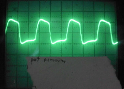
1802 clock pin 1 with pot at miniumum, 1.77MHz according to uncalibrated counter
clock pin at about one turn of pot
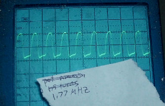
clock pin for best square wave at 1.77Mhz
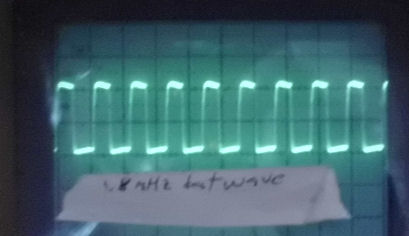
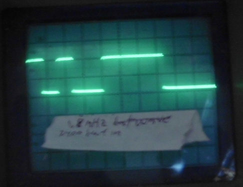
![[baud]](build/clock_18_300in.jpg) examining TTL input and output, which are inverted from RS-232 thanks to transistors.
examining TTL input and output, which are inverted from RS-232 thanks to transistors.
input to EF3 at 2400 baud for CR ASCII 0DH or (least bit first) 0 start bit +10110000 plus stop bits of 1's
output from Q at 2400 baud for CR looks like 0 + 10110001 plus stops
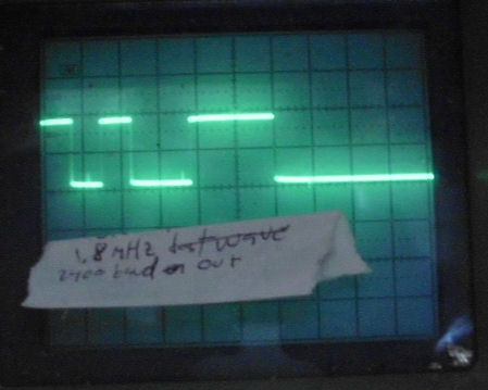
input to EF3 at 300 baud for CR
output from Q at 300 baud for CR - same pattern
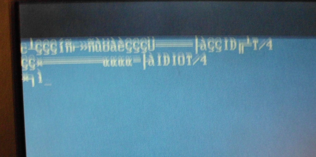
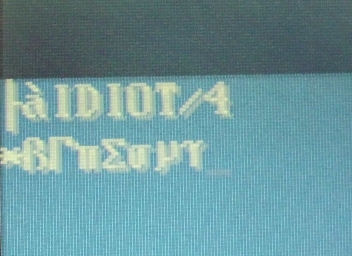
output at screen "IDIOT/4" prompt, then response to "abcdefg"
Results seem to be that Q output bitstream is about one "bit" short, so characters seen with 8th bit high.
(proof: abcdefg -> greek characters in extended ASCII with 8th bit set)
May be some kind of software fault, or timing fault. Theory: since the monitor can produce the "IDIOT/4" prompt when
baud rate is recognized, but can't produce echos of characters, the problem must be on the "receive" side, not the "send" side.
![[2MHz]](build/idiot_1_2mhz.jpg)
I purchased a 2.0MHz resonator and replaced the 1.8Mhz resonator, to see if that would help. I removed the 3-pin
resonator by using solder-wick; the PC board was not damaged. The 2.0Mhz resonator (blue) was lightly soldered in.
![[2MHz]](build/idiot_1_inout.jpg)
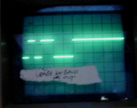
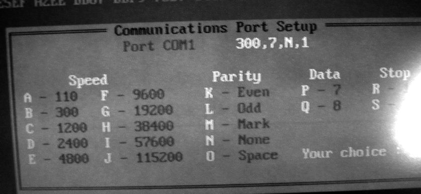
I tried numerous baud rates, settings of parity, 8 or 7 bits. The final combination that worked was 300 baud, 7 bits, no parity, 1 stop" 1200 baud worked for input, commands were recognized, but the output was garbaged. This particular program (QMODEM under MS-D0S) did not offer 600 baud. (Lee Hart read this and suggested: "Try setting your terminal program for TWO stop bits. As I recall, that's what UT4 and IDIOT are built for, because teletypes needed 2 stop bits. I'm not sure if it will matter, but it's worth a try.")
On the right, you can see the EF3 input (top) and Q output (bottom) for [CR], 0D hex. I adjusted the horizontal so 1 bit
was about 1 horizontal division. The least signifigant bit is to the left. Active is low.
So we have 1011000 - remember, 7 bits. i tried other keys to verify the pattern: A, B, D, H, M. (31, 32, 34, 38, 40 hex).
![[2MHz]](build/idiot_1_scr.jpg)
As the screen shows, I tested some of the IDIOT commands. Here's a summary sheet of them.
?Maaaa cc means dump from address aaaa for cc bytes.
!Maaaa dd dd dd dd[CR] means write to address aaaa the bytes dd, dd, etc.
?Maaaa cc !Mbbbb[CR] means move from address aaaa for cc bytes to address bbbb
?R means dump the 1802 registers.
This page and edited content is copyright Herb Johnson (c) 2016. Contact Herb at www.retrotechnology.com, an email address is available on that page..