![[Intecolor remnants]](isac_boxes.jpg)
This Web page last maintained April 18 2010; updated June 20 2024. To see my vintage computer restoration home page, follow this link. My S-100 Web pages have a home page at this Web link. To contact me, please follow this link for ordering information, terms and conditions, etc.
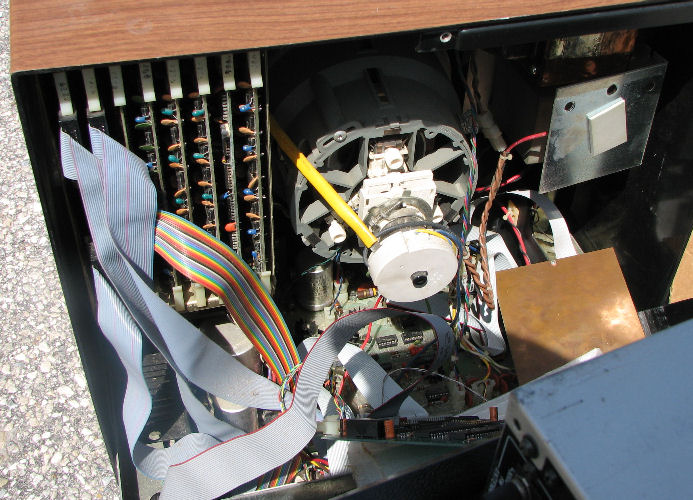
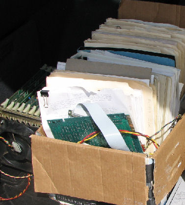
Intelligent Systems Corporation built some 8080 systems which supported programmable color CRT monitor based terminals, from the late 1970's and forward. In March 2010 I acquired an Intecolor 8052 board set with docs, by literally pulling the card cage out of an abandoned 19" color TV CRT monitor. The 8080 based CPU board had I/O, ROM and RAM. While the cards look something like S-100 cards, they are NOT S-100 compatible - the signals don't match at all. I also acquired a box of docs, and the dual 5.25 inch floppy drives.. Embedded inside that monitor was also a Ampro Little Board Z80 card and docs. The linked Web page shows how I revived that card.
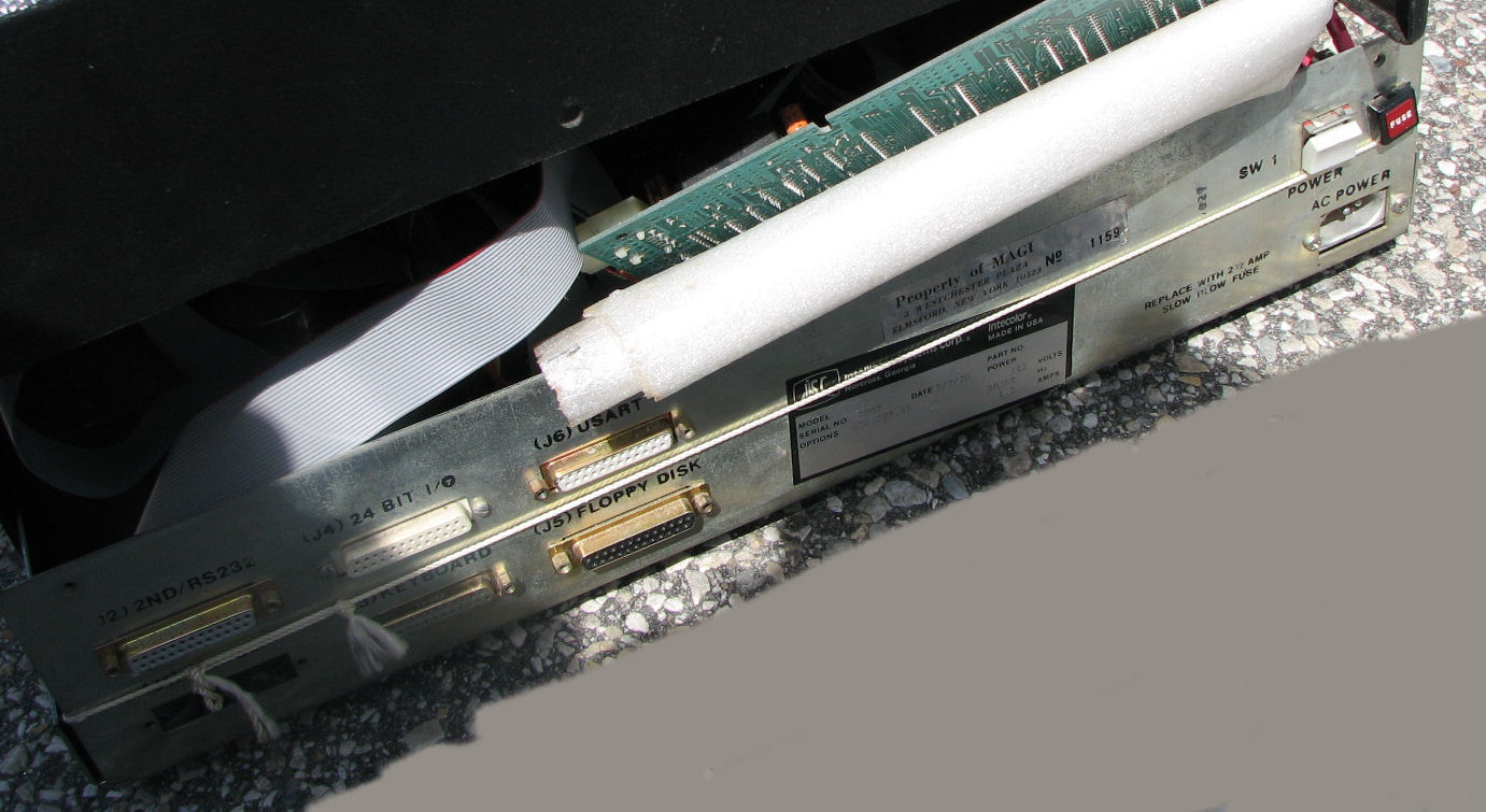
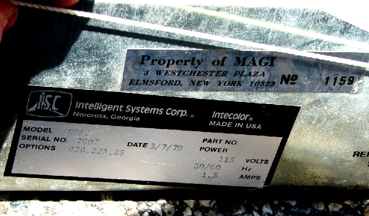
Docs for the Intecolor 8001 describe these digital modules: CPU, I/O cards, PROM/RAM, Refresh RAM, keyboard, floppy disk, floppy tape recorder, motherboard, Display Generator, LIght Pen. These fed a CRT Color monitor; the cards were mounted inside the monitor and powered by it. The floppy controller card uses a WD 1771 FDC chip. Access to external devices was from the back of the monitor. Looking closer at the rear of the monitor, I photographed the nameplate and the 1979 origin date of this computer. It was just too much grief to lug the big ancient color monitor home.
Thousands of these ISC programmable terminals were sold in the 1980's and 90's. ISC the company went through a number of other companies, including Rockwell Automation. Today (2010), support for ISC products WAS available from "intecolorterminals.com" from Peripheral Exchange LLC (that site is not available in 2024). They provided later model ISC products and PC based emulators for those and earlier products including the original 8001.
- Herb Johnson
From larger document, pages 64-92. BASIC says "same as the original BASIC Ver 12.8.76 with the following extensions for FCS". Followed by notes of various sorts about the FCS (File Control System).
Siemens Model 82 microfloppy operation and maintenance manual. Poor copy. about 100 pgs.
ISC 8001 monitor maintenance manual. Schematics, waveforms, tuning. Pages 49-83 plus schematics.
binder, "how to use the 8001 CRT". Discussions of Light PEn L_-200-05, plotting, back connectors. Appendix on TMS 8080 processor, TMS 5501 I/O controller, monitor adjustments. Then sections on ISC computer itself - block diagrams, schematics for computer "modules". Another section is "BASIC 8001". Another section discusses the "CPU O.S." on two EPROM's, essentially a ROM monitor. Looks like it accepts Intel Hex format records. Then there are some pages on operation of th 8001.
binder, untitled, poor copy. "This manual is intended to be a user's instruction manual and reference guide for the Intecolor terminals and microcomputer systems based on the 8001 terminal, including the newer 8300 and 8900 series units." Apparently different models had differnet sized CRT monitors. This manual seems to have the same schematics as the above manual. The card cage and installation are described in more detail, including pages on "module" slots. Apparently the cards or modules must be in specific card slot positions. The boards are described in more detail in this manual. Another section of this binder, is the "ISC Maintenance manual", mostly for the CRT monitor. another section is the "Extended Disk BASIC" appendix. dated 8/1/79. Another appendix is the "File Control System" or FCS commands. another is DEBUG. There are installation instructions for various "options", which amount to boards or software installation. An EPROM programmer is mentioned, through an I/O card.
binder, ISC PROM code listings. Keyboard handler, printer routine, Utility subroutines, CPU OS, 48 line I/O, ISC Disk A Handler Ver 2.0, same for "B", File Control System, FCS command Input Routine.
Folder with FIG Forth An adaptation of FIG (Forth INterest Group) FORTH for ISC. Paper listings, probably the first several pages will have the adaptations of 8080 FIG FORTH to the ISC computer.
folder, CAIIG NEWS First three issues (1981-82) of the newsletter for the Central Atlantic ISC Interest Group of North Carolina. Apparently they arranged a purchase of about 37 Intecolor terminal from "MAGI in upstate New York" through Xerox Corp. in 1980. Many of the purchased terminals were incomplete. A list of members suggests a few dozen people were involved and obtained these terminals. Someone was working on a CP/M like OS they called "CLiD".
folder, Intecolor catalog, poor copy NO pictures, a list of products with features and prices. Also software, options, spares are listed and priced.
folder, Intecolor 8050 series Extended Disk BASIC manual, poor copy Aug 1979.
CAIIG Library. Games (3 disks), Applications (2), Demo, Utility, FORTH, MAGI, SEND, Contributions.These are discussed in the newsletters. Two boxes which each contain a set of these disks. One box has a disk "ROM Source and Programmer". Another box only has CLiD (3 disks), WP word processor, and several Games diskettes.
Expedited for purpose June 2024, processed photos of key ISC 8001 documents and boards. Scans of documents later.
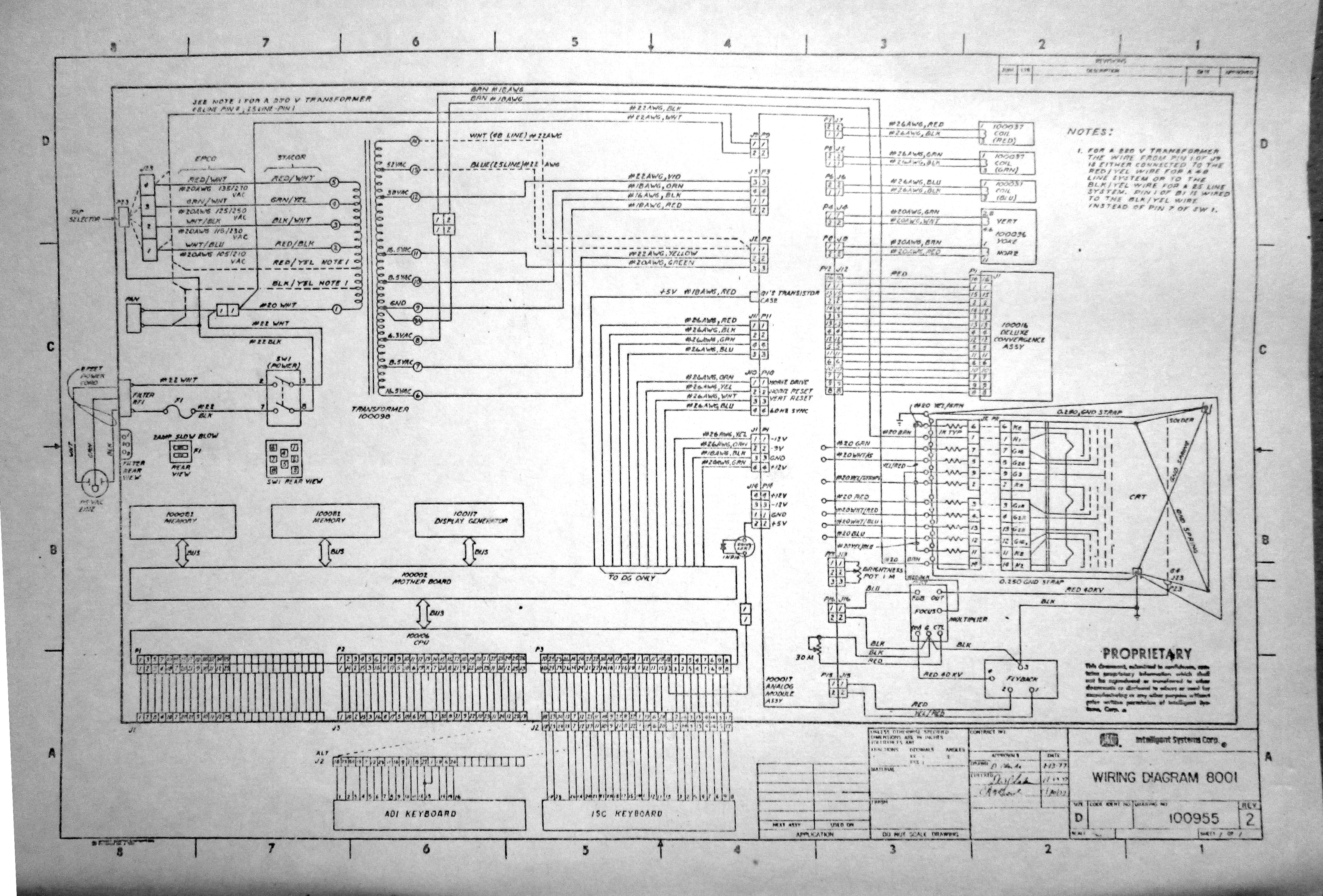
ISC Intecolor wiring diagram.
ISC Intecolor 8001 analog wiring
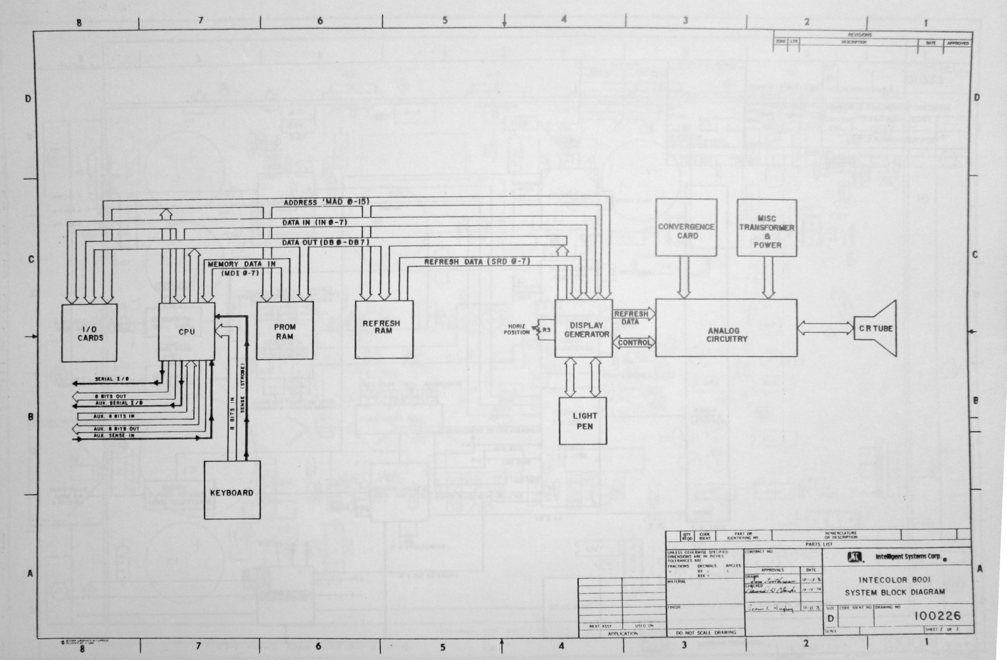
ISC 8001 system block diagram
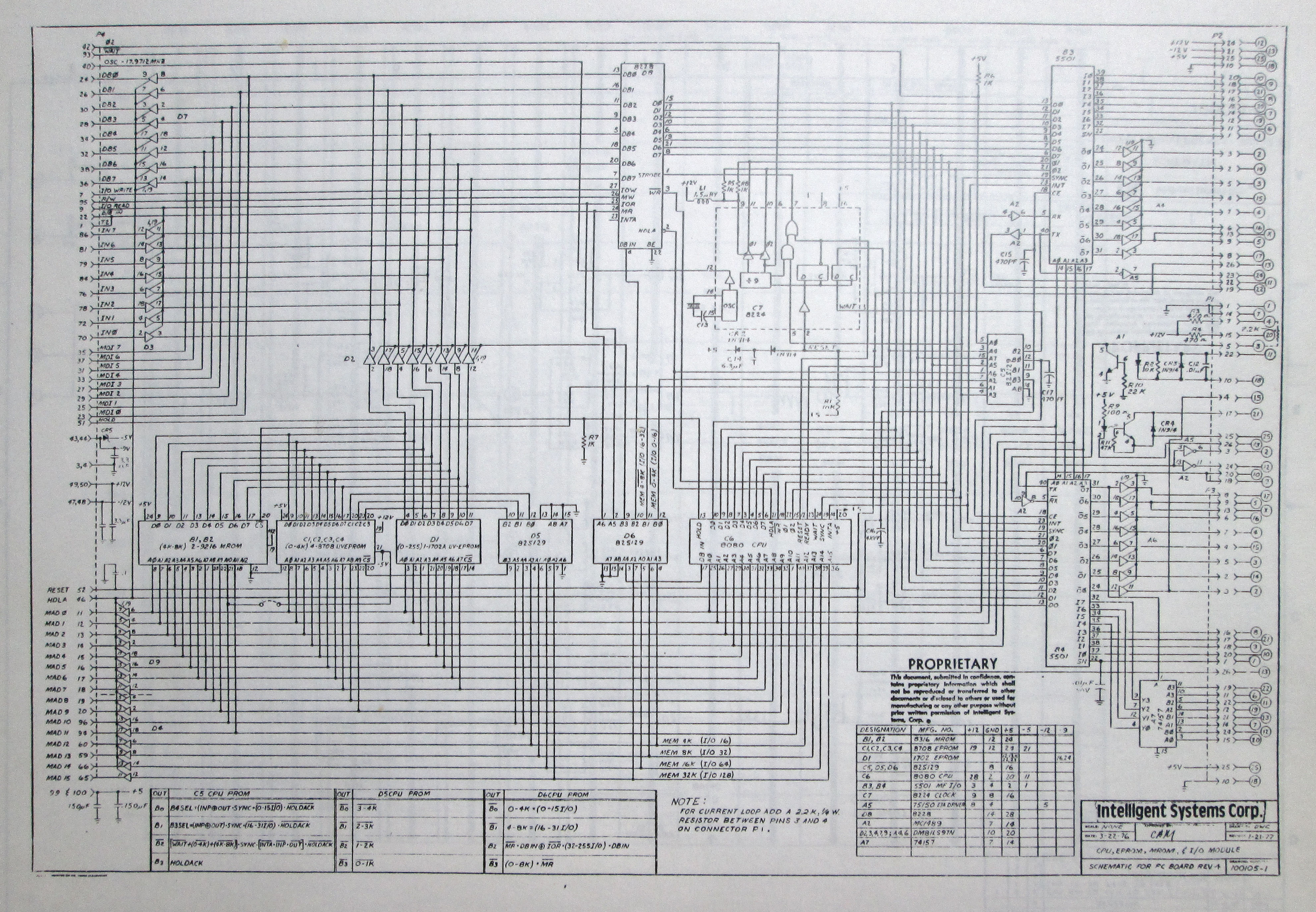
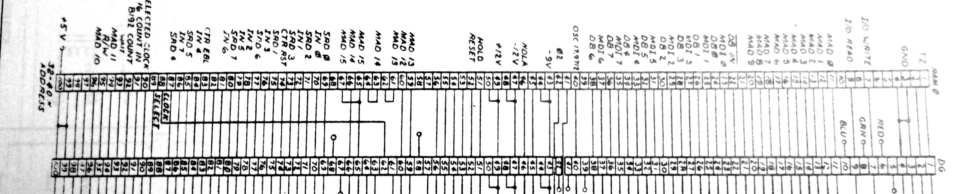
ISC Intecolor 8001 CPU schematic - this is key to interpreting the bus
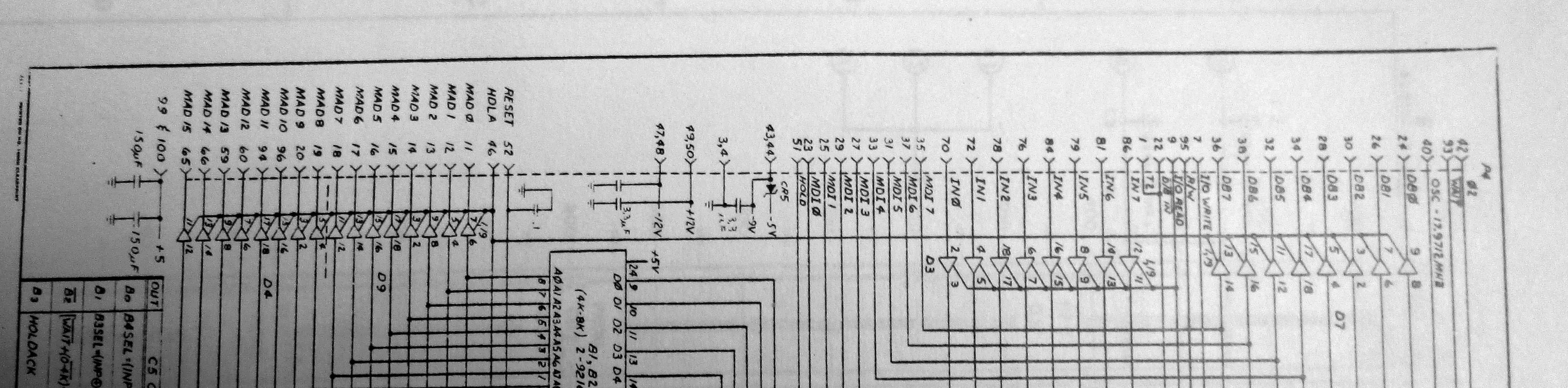
closeup of schematic bus connector signals
ISC schematic, bus signals by number
Additional ISC boards, obtained in 2020's; physical details
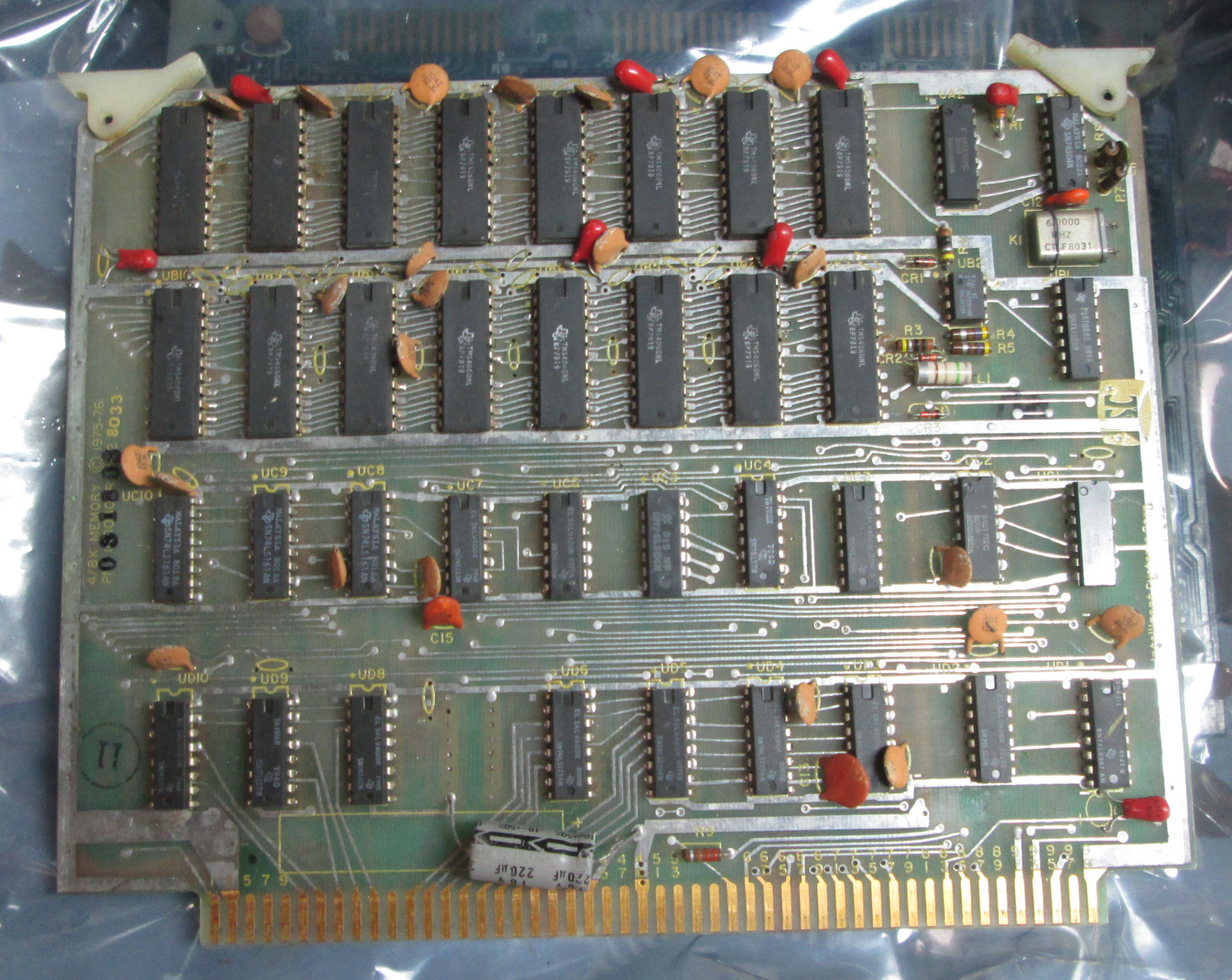
ISC 8K memory board
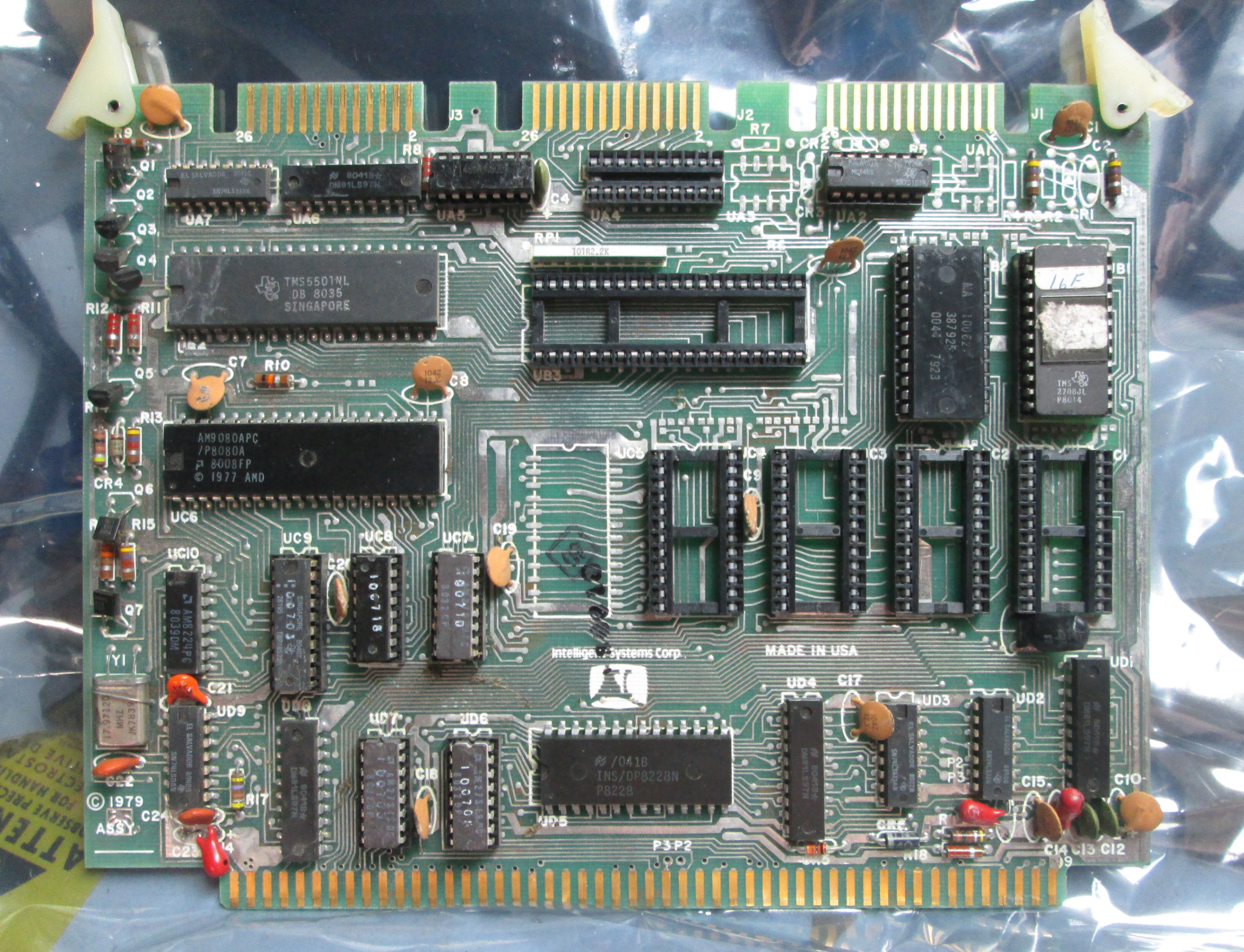
ISC CPU board
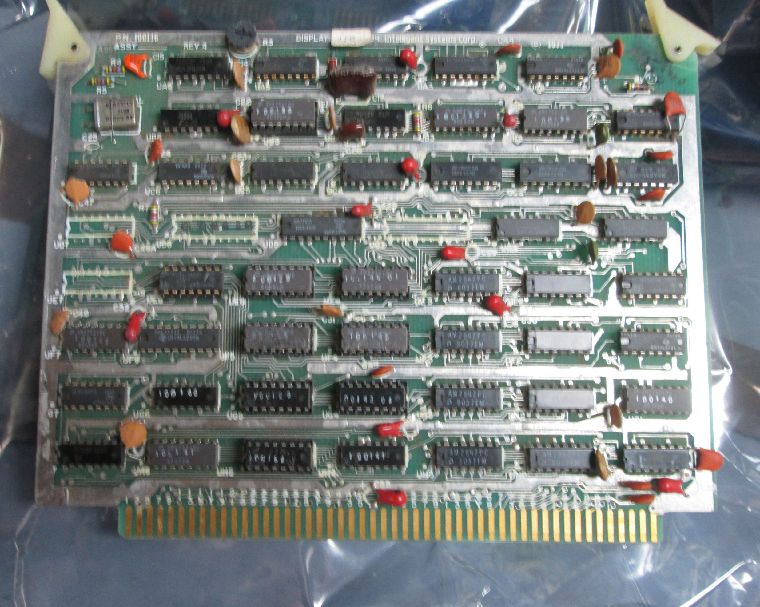
ISC display board
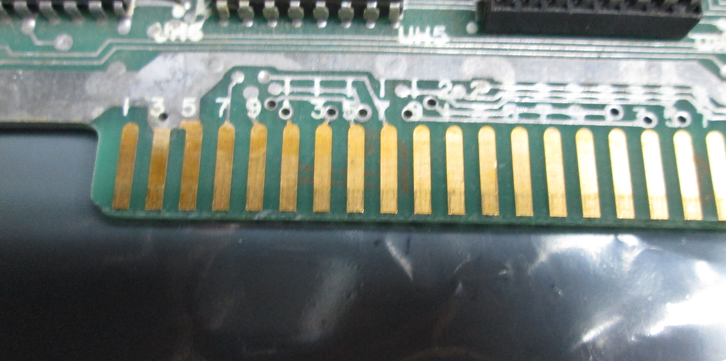
closeup of a ISC memory board showing ISC pin numbering
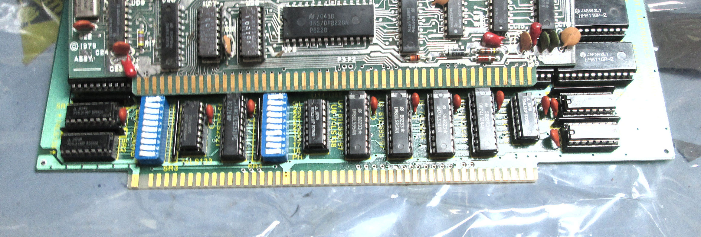
ISC (top) vs S-100 edge connectors, component side, showing mechanical differences
closeup of a ISC memory board to show pin numbering scheme
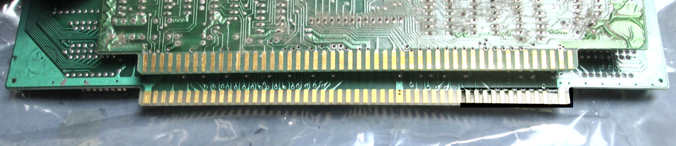
ISC (top) vs S-100 edge, solder side
I've had contacts in 2023 and 2024 about the Intecolor 8000. I found a 2023 discussion at a VCFed forum. These encouraged me to update this Web page.
The Compucolor product line covers two different designs. The apparently earliest ISC model is the Compucolor 8001 AKA Intecolor 8001 from 1976. It consisted of several digital logic (8080) boards in a card cage, in a color CRT TV-like chassis - the model described on this Web page. Later Compucolor models were in a custom terminal chassis and had a single-board digital logic (8080, Z80). Much of the 2024-present online documentation for and content about "Compupcolor" is of later models. A good example is the Compucolor II Tribute Web site by Jim Battles. Also, bitsaver.org has later Compucolor documents.
A Web search in June 2024 found a Web site with a comprehensive description of the earliest card-cage version of the Compucolor 8001 oldcomputers.net entry for the Compucolor 8001 computer. The page probably dates on or before 2014.
This Web page on the Intecolor 8001, precedes most of these other sites. But my page was essentially a place-holder about an odd vintage computer I found and salvaged at a 2010 hamfest. With recent interest in 2023-24, I'll update my Web page to reflect some of my resources and see about making my documentation available. - Herb
A customer of mine and others, raised the question "is the Intecolor bus S-100"? The answer is NO. The physical connector has the same pin-count and spacing as shown in this comparison photo. But look closer: the PC boards are of different widths and the edge connector is offset differently between the two boards. So a S-100 card just won't fit in the ISC card cage; and an ISC card would be loose in an S-100 card cage.
Also: the signals are different, starting with the power pins. Images of the CPU schematic and closeup of the bus signals above, reveal the Intecolor 8001 signals including DC power connections. Key signals seen visually on the PC boards, are the ground and +5 pins. Visually, the wider PC traces suggest the leftmost and rightmost pins on the two connectors are different ground and DC power connections. Also, the S-100 bus generally uses unregulated DC voltages; the ISC bus has regulated DC voltages.
A point of confusion: pin numbering
Some ISC cards are marked to show the edge connector signal numbers, from 1 to 100. As in this closeup of a ISC memory board, ISC numbers edge connector pins by odd-numbers on the component side: left is 1, right is 99. Based on the schmatics, the even numbers from the solder side are: left is 100, right is 2; because physical through-hole connections between pins are one-number apart. Put another way, the ISC bus numbers, looking on the component side from left to right THROUGH the board (that reverses the back), like this: 1 top, 2 back, 3 top, 4 back, .... 99 top, 100 back. From a ISC schematic, see bus signals in sequential number, revealing ISC functions including thru-hole connected ground and power pins.
Documents about the MITS Altair / S-100 bus are linked here on my Web site. The S-100 bus signals are physically ordered as follows. Component side, left is 1, right is 50; solder side, right is 51, left is 100. So S-100 pin numbers THROUGH the board, are NOT one-number apart.
pin for pin comparisons, DC voltages
How does that look? I number out below, a portion of the ISC and S-100 pins, again viewing from the component side left to right THROUGH the board. They compare like this:
Physical bus pin numbering order, from component side view THROUGH board to solder side:

1  3  5  7  9  11 13 15 17 19 21 23 25 27 29 31 33 35 37 39 41 43 45 47 49 51 ... 97 99  ISC
1  2  3  4  5  6  7  8  9  10 11 12 13 14 15 16 17 18 19 20 21 22 23 24 25 26 ... 49 50  S-100

2  4  6  8  10 12 14 16 18 20 22 24 26 28 30 32 34 36 38 40 42 44 46 48 50 52 ... 98 100 ISC
51 52 53 54 55 56 57 58 59 60 61 62 63 64 65 66 67 68 69 70 71 72 73 74 75 76 ... 99 100 S-100
I stopped halfway because that's where the ISC has DC voltages on its pins. Here's how ISC grounds and DC voltages compare between the ISC bus and the S-100 bus, physical pin-for-pin.
		ISC	corresponding		S-100
ISC #  		function	S-100 pin	function
3		GND		 2		-18V
4		GND		52		-18V
43		-9V		22		/ADD DSBL
44		-9V		72		PRDY
47		-12V		24		PHI 2 or 0 clock
48		-12V		74		/PHOLD
49		+12V		25		PHI 1 clock
50		+12V		75		/PRESET,
99		+5V		50		GND
100		+5V		100		GND
I don't see the point, of cross-referencing all the ISC vs S-100 pins. It's clear these two busses are not compatible - neither mechanically, nor pin-position-signals, nor DC power voltages. While a S-100 breadboard might be cut to fit the ISC cardcage, a S-100 designed board won't have the right signaling, and won't physically fit the card cage. Other considerations will be for another time. - Herb, June 2024
Copyright © 2010, 2024 Herb Johnson