![[System 00]](sys00_insp_corner.jpg)
![[System 00]](sys00_exhibit_front.jpg)
This Web page created July 8 2019, by Herb Johnson. Photos by Herb Johnson with permission from The Sarnoff Collection. Copyright (c) Herb Johnson 2019.
In Nov 2018 I had an opportunity to inspect the System 00 with its covers removed, at its Sarnoff Collection location. This Web page has my photos, and commentary about what I saw at the time and considered later.
Left and right in this description of the System 00, are referenced from the front of the system.
My description of the Weisbecker "System 00" is on the linked Web page. On the cosmacelf.com Web site, is the PDF of the 1971 System 00 manual, as obtained from the Hagley Museum. The "publications" section of that site includes a description of the manual, the background of the System 00, and other references.
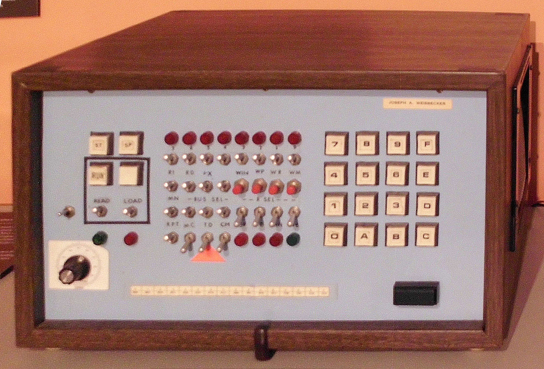
Here's the System 00 as exhibited.
A close up of the System 00 front panel.
An exterior view of the boards from the left-rear corner.The front is at photo-right.
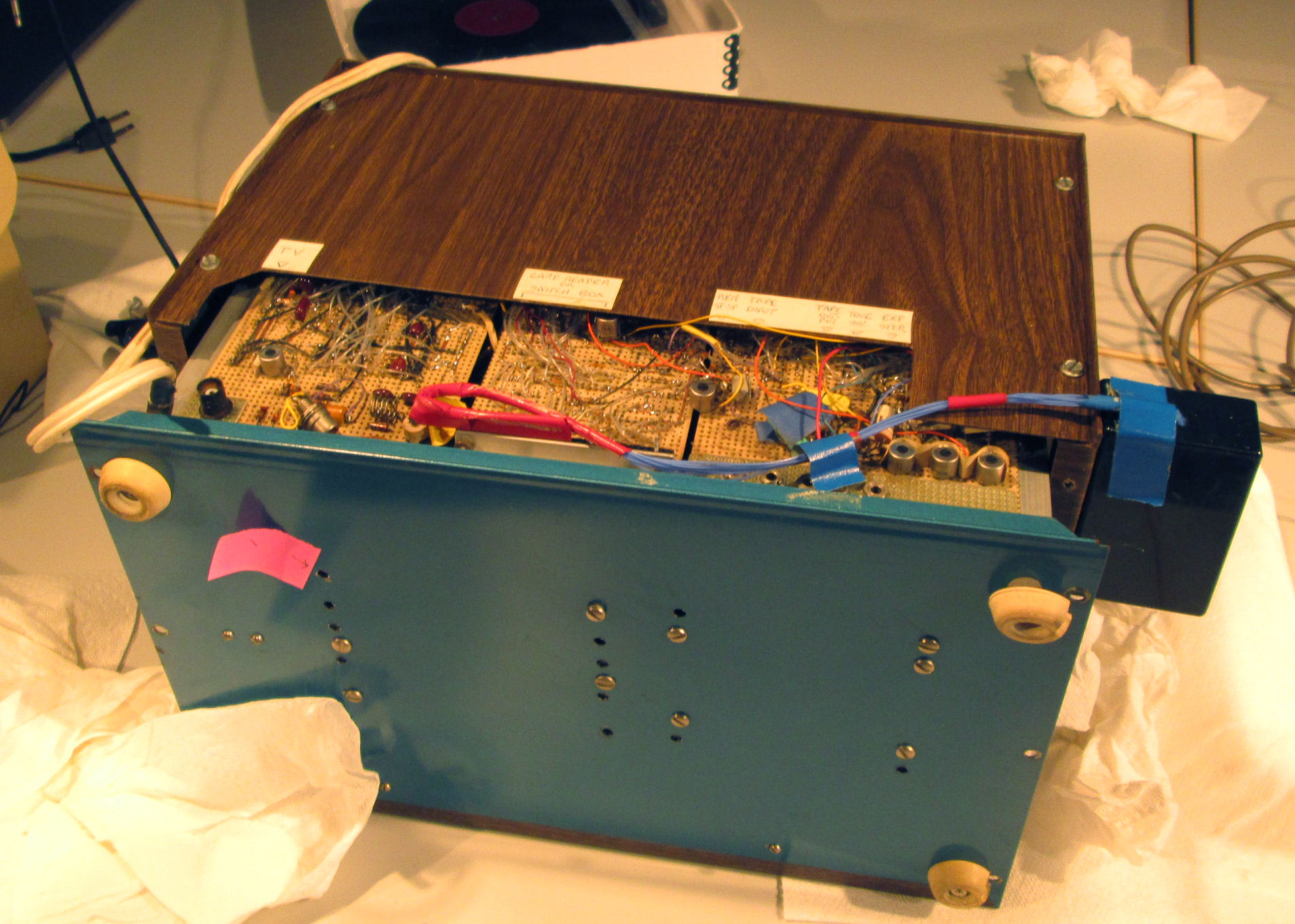
With the cover removed, you see the immediate interior of the System 00.
Here's the cover partially removed, rear view. Note there is a small black box on photo-right. It holds a connector; the blue cable extends across the lower back.
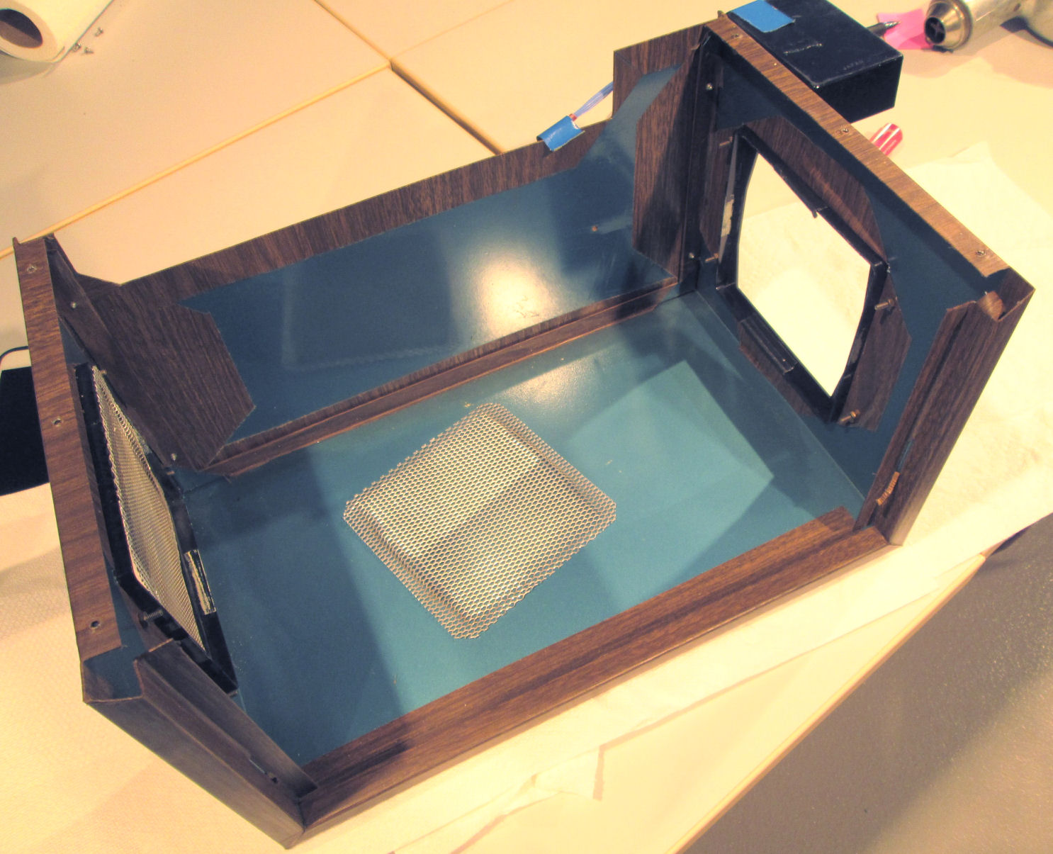
Here's the interior of the cover.
The cover is blue sheet metal, covered with "Contac" paper with a printed wood pattern.
One of the two metal grates, normally on either end of the cover, is lying unmounted on the cover.
An exterior view of the boards from the left-rear corner.
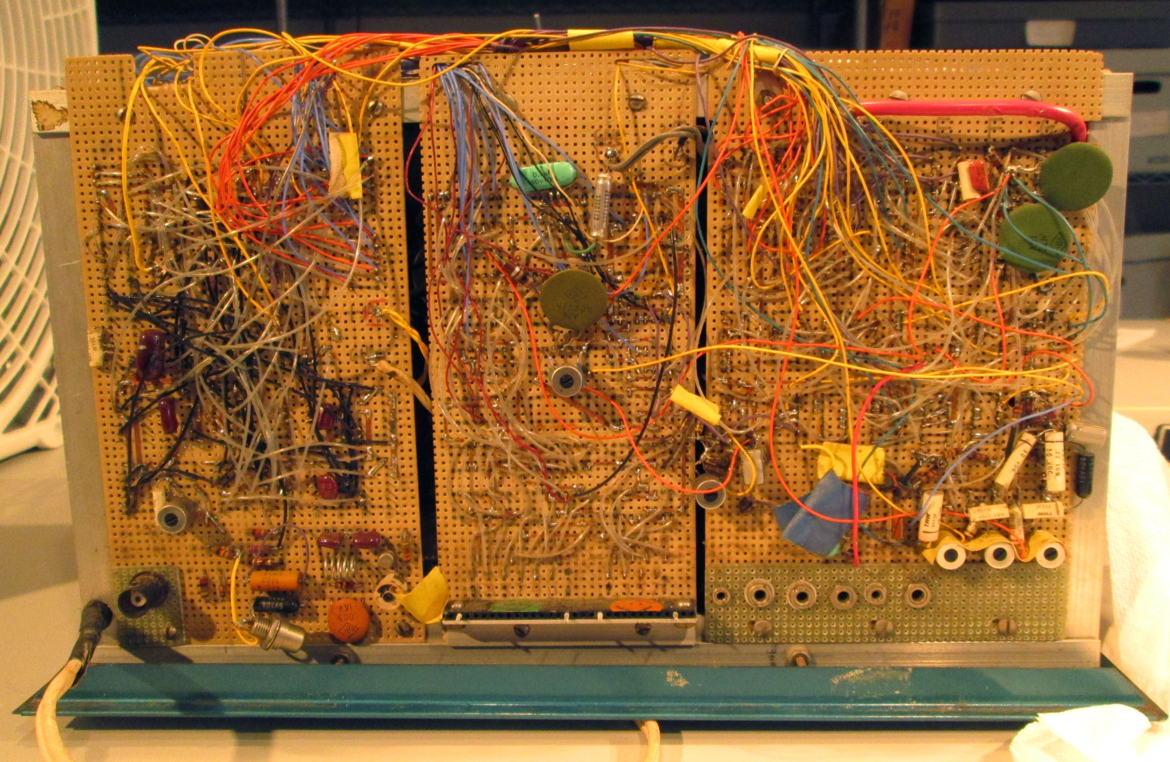
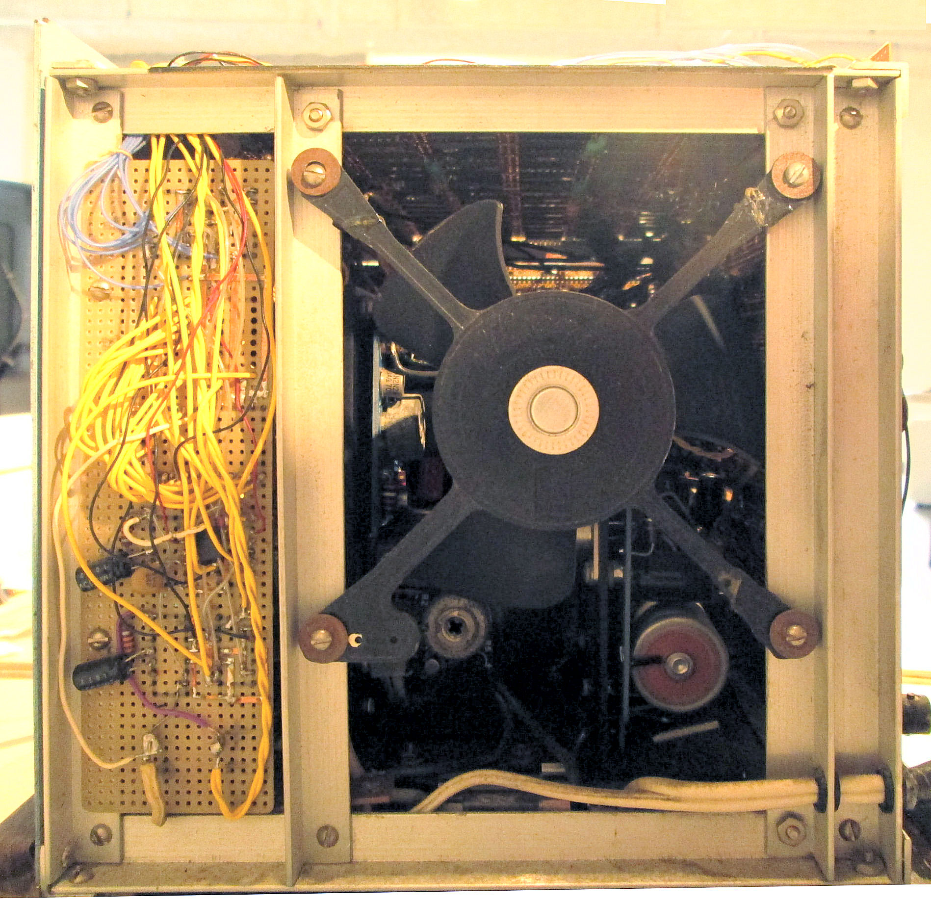
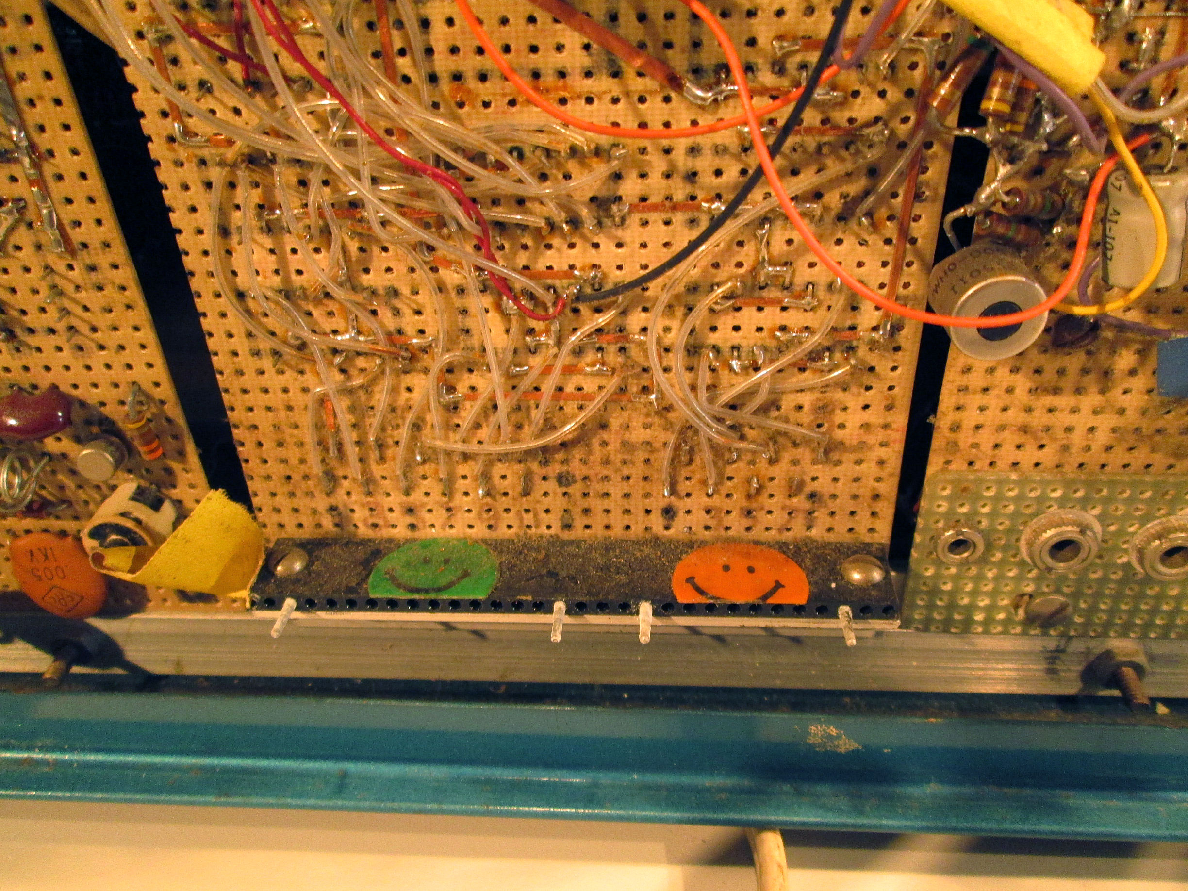
With cover removed, the System 00 construction is shown to be a set of pre-perforated boards, of hand-wired small IC's and components. The wired-side of the boards faces outward on all sides. A fan blows air through the interior where the IC's and power supply are exposed.
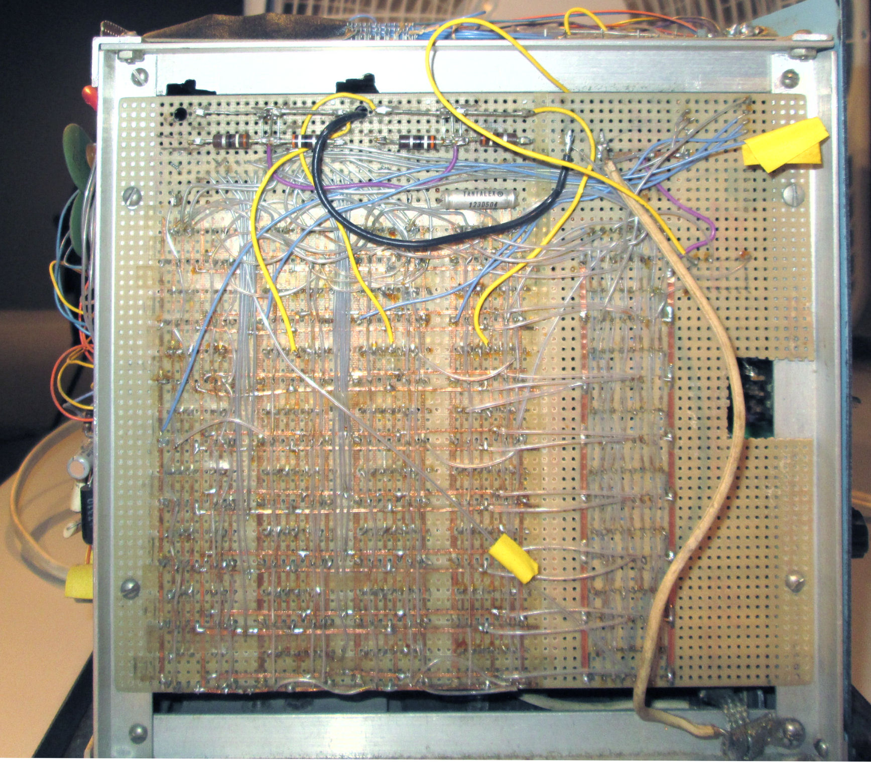
A rear view of System 00 boards. "Phono jacks" are visible along the photo-right. A BNC connector is on the far left of the photo. Other circular items are potentiometers (variable resistors).
The right side, referenced from the front; and the fan. The large components inside are part of the power supply.
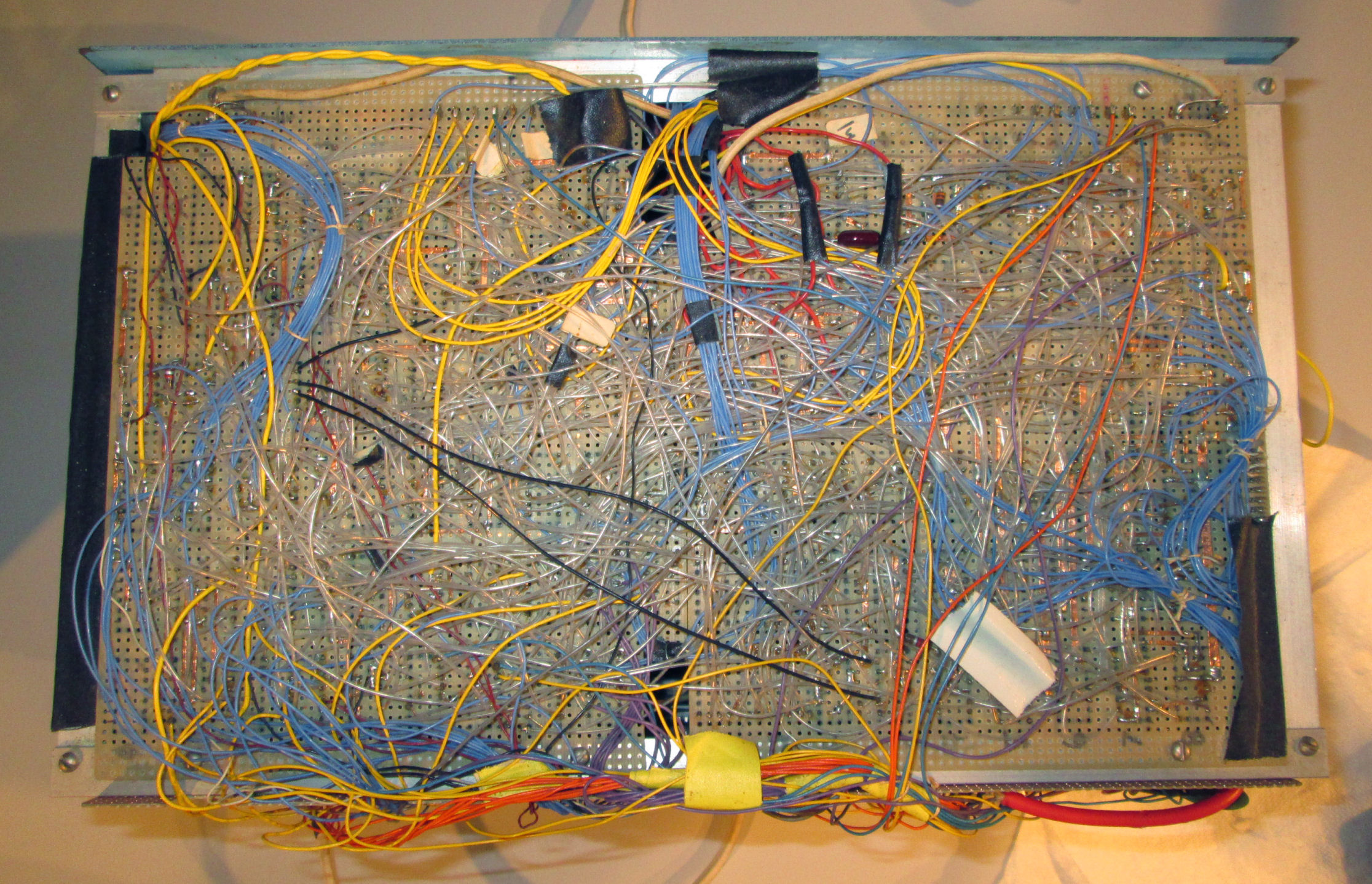
The left side. The cover has an opening on the left side, so air flows through the system. Note the regular pattern of wiring, of five sets (horizontal) of eight components (vertical). That could be correlated with schematic information of similar components wired in parallel.
The top. The right side of the photo is the top edge of the front of the system.
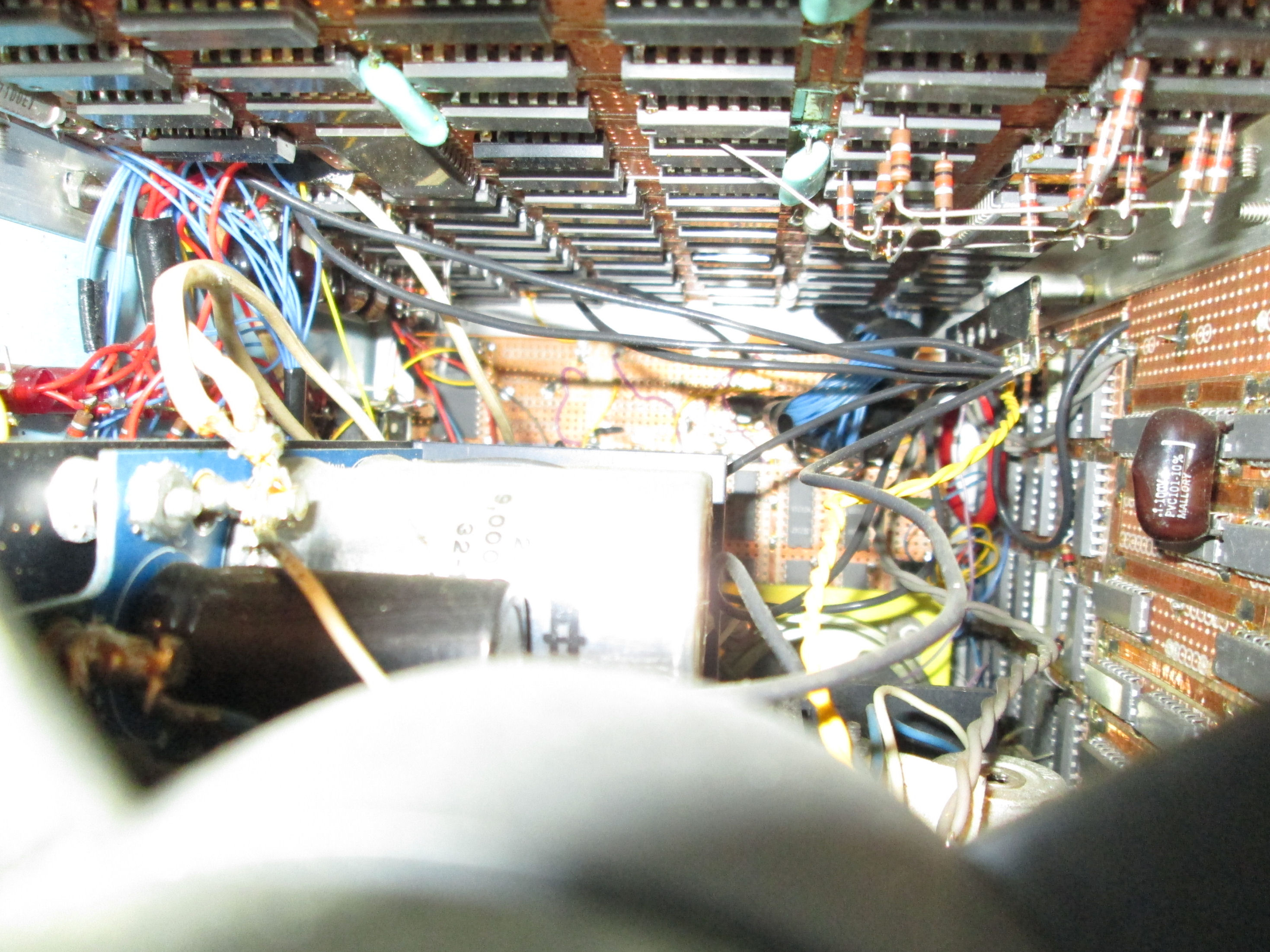
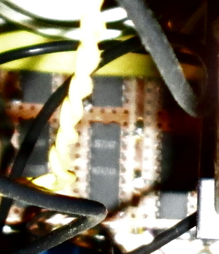
The System 00 was not disassembled further, so a view of the interior was obtained through the opening provided by the fan. A flash photo of the interior showing the IC's and power supply. Photo-left is the front of the System 00; I see some LED's.
The interior photo is not well focused, and most of the IC's are not facing the camera view. Here's a closeup, enhanced and rotated, of the side opposite the camera. It's not easily read, but the IC shown, appears to have a Signetic brand capital S and a four-digit date code; and a part number possibly N7474A.
This would indicate a Signetics brand TTL chip in the 7400-series family. That TTL family is consistent with System 00 schematics in the "System 00" manual of 1971. The schematics name Signetics 7400-series logic. The "look" of this chip, is consistent with the "look" of most of the other chips shown. So it's plausible to assume, the System 00 "logic" was constructed largely of 7400-series TTL logic.
The System 00 was hand-wired, with components mounted on .1-inch perforated circuit-board material. This was often a method of one-off or hand-produced electronic construction in the 1970's.
A view from the uppper corner, shows most of the
construction from the wiring-side of the System 00 boards. Hear's a close-up, of the back near the external connnections.
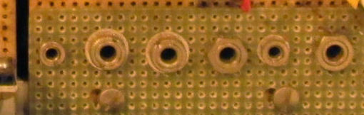
The System 00 had several connectors for external devices. These connectors were either
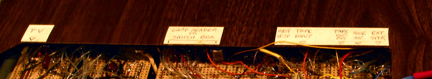
in the rear, and labled on the case; or on the left side. Here's a closeup of the rear phono connectors. Here's the lables for the rear connectors, from the cover. The lable "switch box", refers to the
boxed connector on the left (seen from the front). This
is an inside view of that small boxed connector. the blue wires shown, are also visible
along the bottom edge of the rear-view. The lable "TV" refers to the BNC connector, visible
on the left side of the rear-view.
Copyright © 2019 Herb Johnson