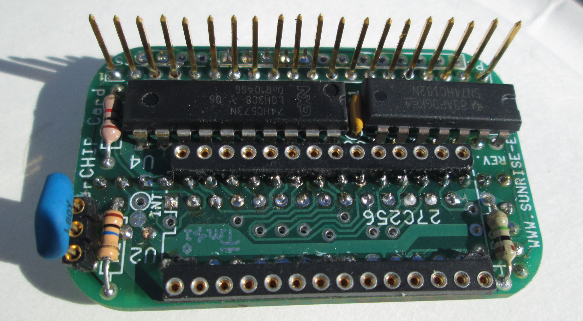
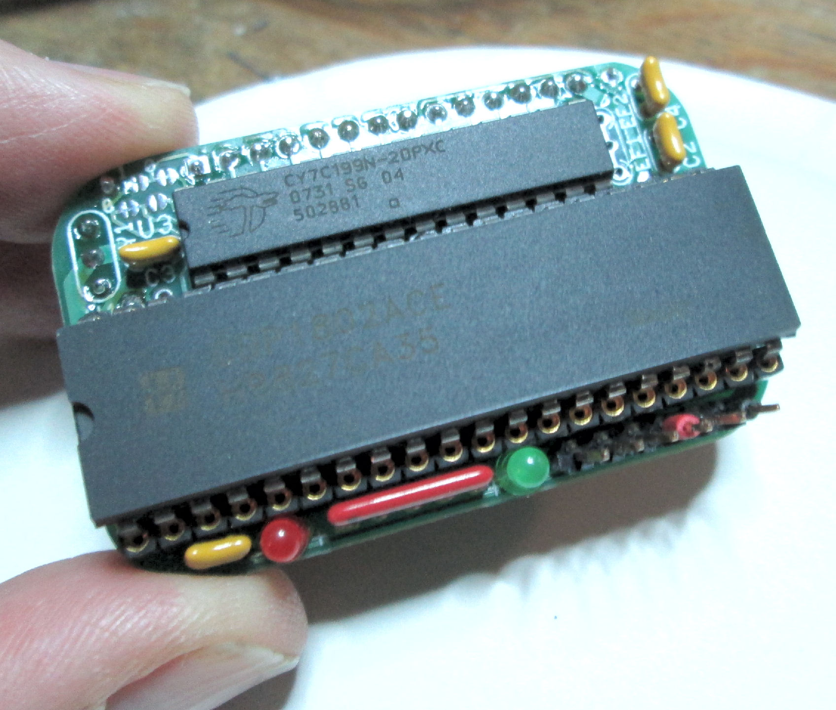
![]memberchip]](mchip_done_cpu.jpg)
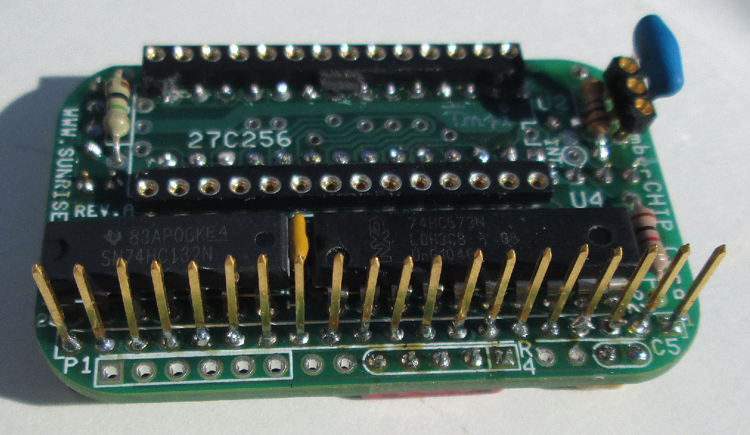
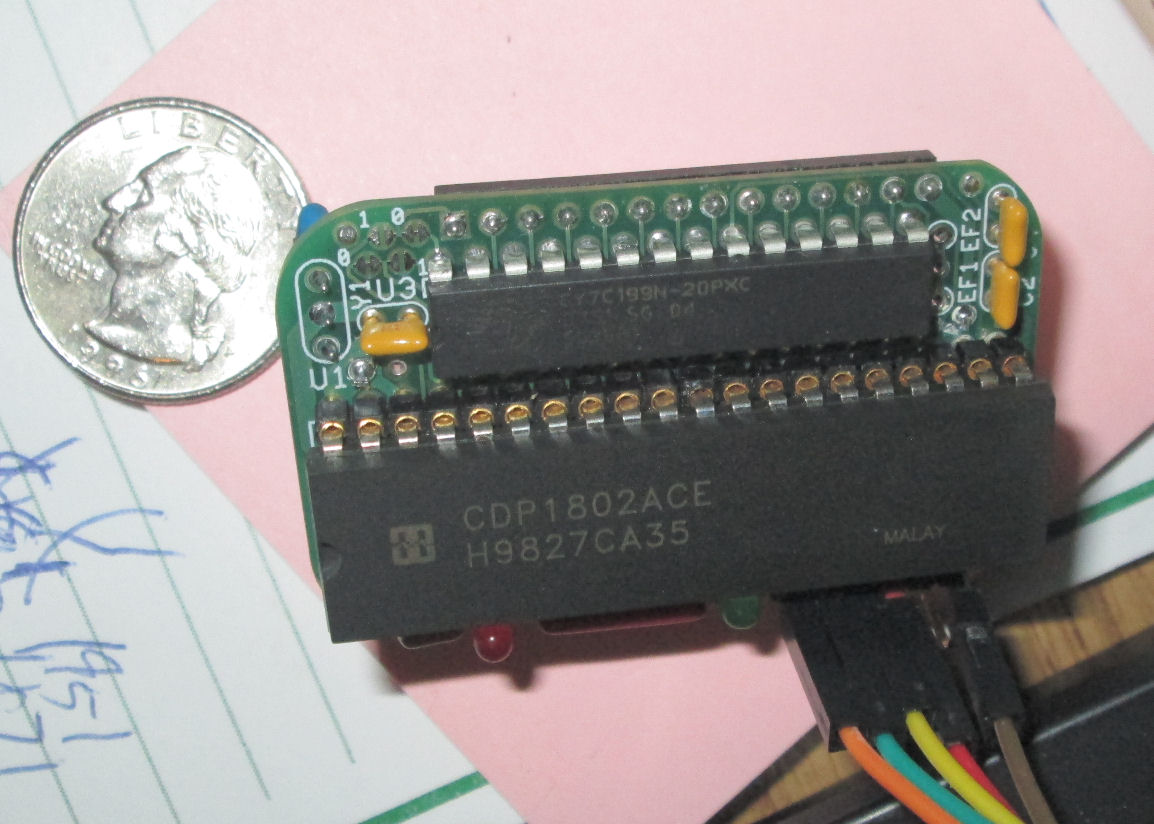
![[memberchip]](mchip_done_rom.jpg)
Page last updated Mar 1 2026. I built a Lee Hart 1802 MemberChip board Rev A in Nov 2020. Here's some of the build details in photos and brief descriptions. I've made a number of mods not in the kit. Also there's some errors I undid. In addition, I built an I/O card based on schematics in the manual. To attach the I/O card I did not use a 40 pin IC socket for the 1802. I used two 20-pin header sockets. Read my notes before you build your MemberChip Card!
Current information: Here is the current Rev A manual for 10 May 2025.
Here is the current Rev B manual for 21 Jan 2026. It has a larger ROM.
For current kits and most-recent ROMS for the 1802 MemberChip Card, contact Lee Hart directly at
Lee Hart's MemberChip sales page.
The MemberChip was a final entry
in the 2023 Hackaday contest.
Look at the Project Logs there for more notes about the MemberChip card software and hardware. - Herb Johnson
Here's a manual and schematic for a Rev A 2021 model, much like the late 2020 kit I built.
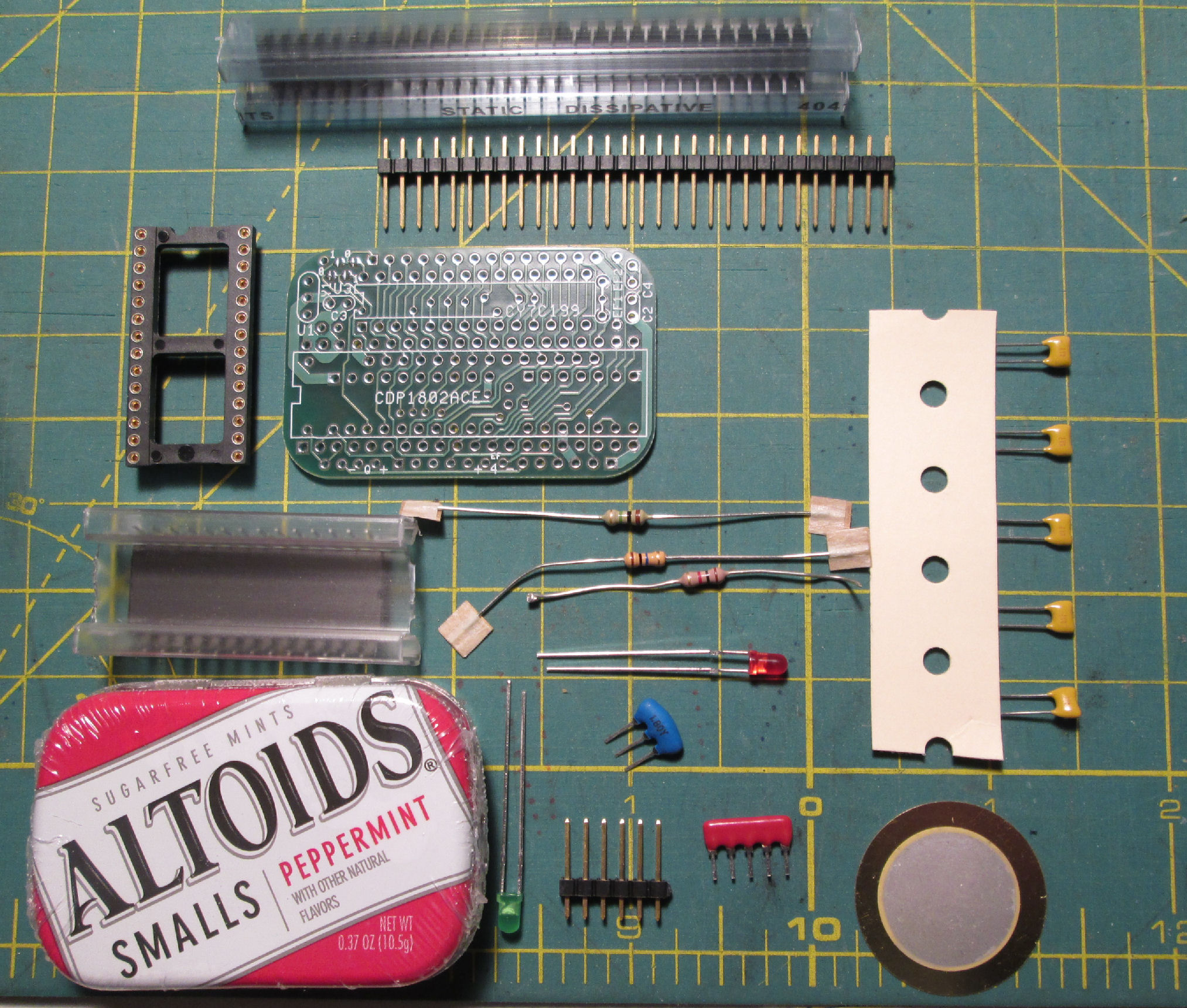
parts as provided in Lee Hart's kit.
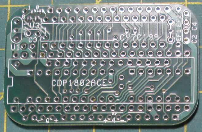
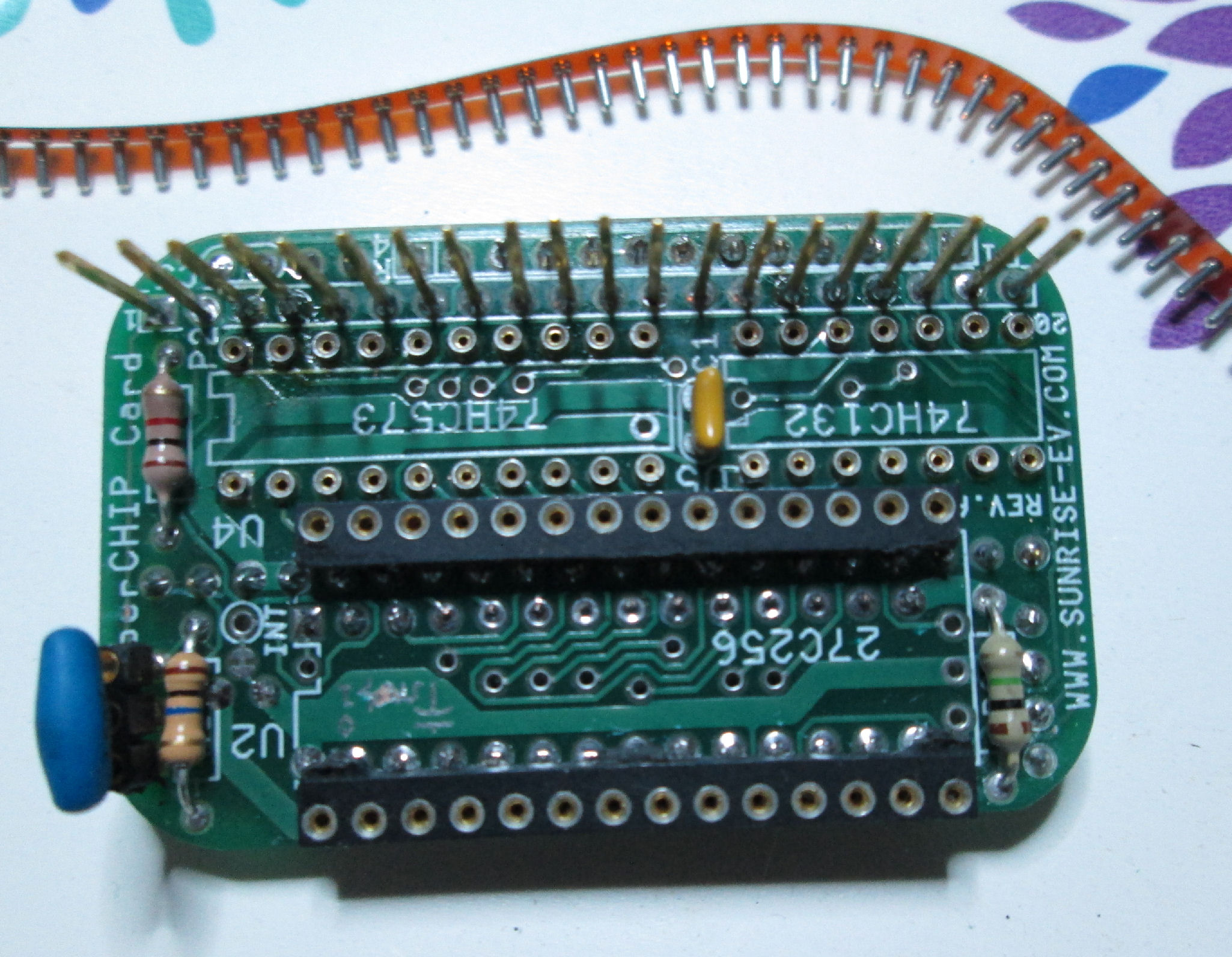
CPU side of circuit board
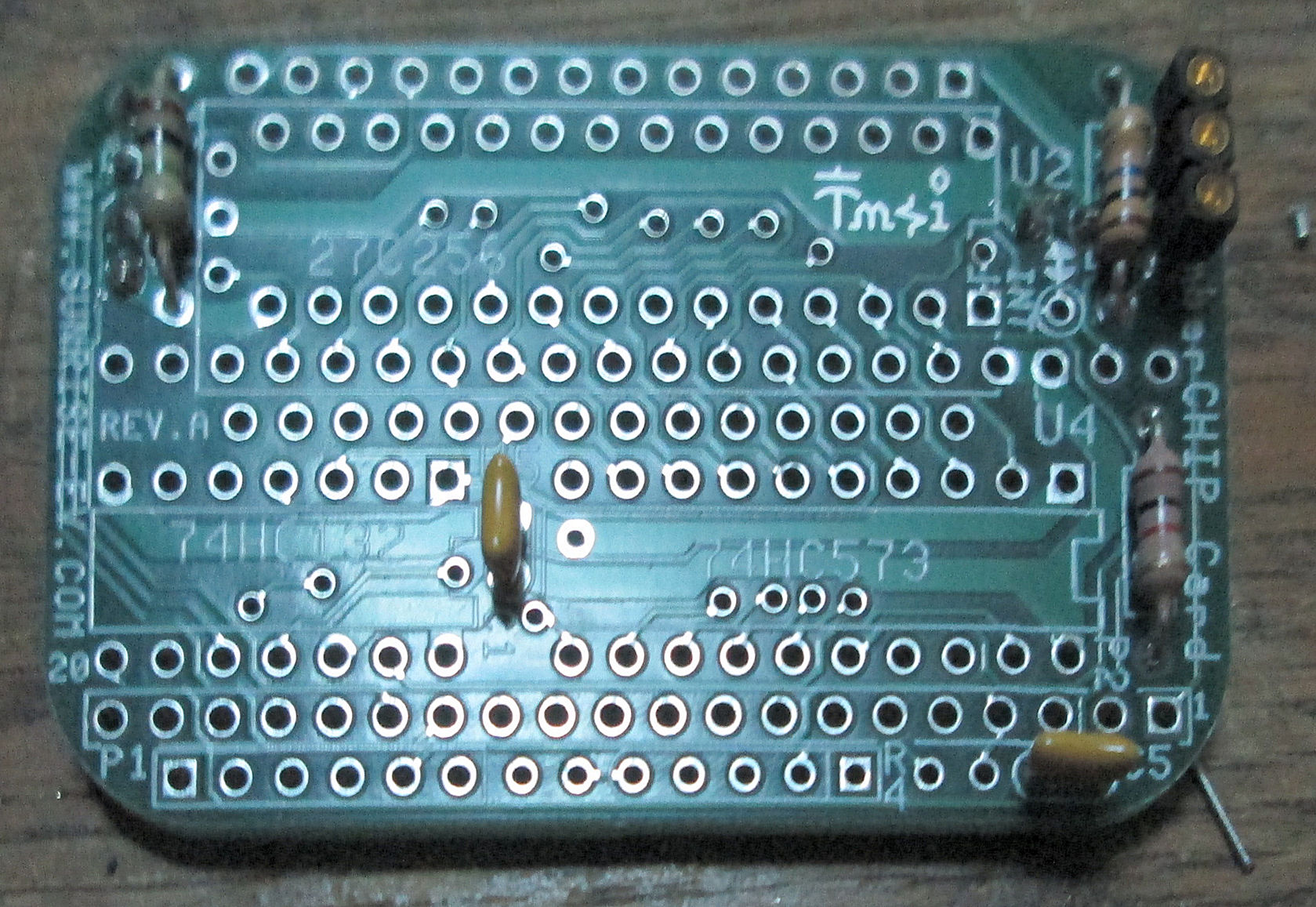
ROM side of circuit board, some components installed
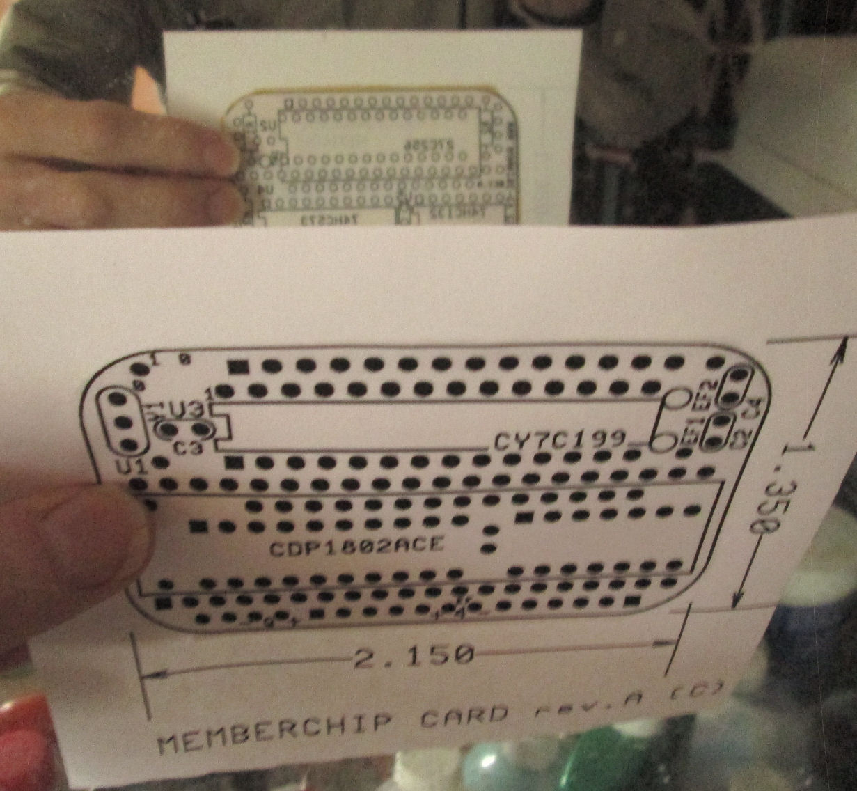
I pasted two photocopies (one mirrored) back-to-back as one document, to assist me in construction.
here's the pasted up result
I added a 3-pin socket for ceramic resonator, to change speeds.
install socket pins from strip, even for TTL
I used a 40-pin socket to align the header and CPU socket
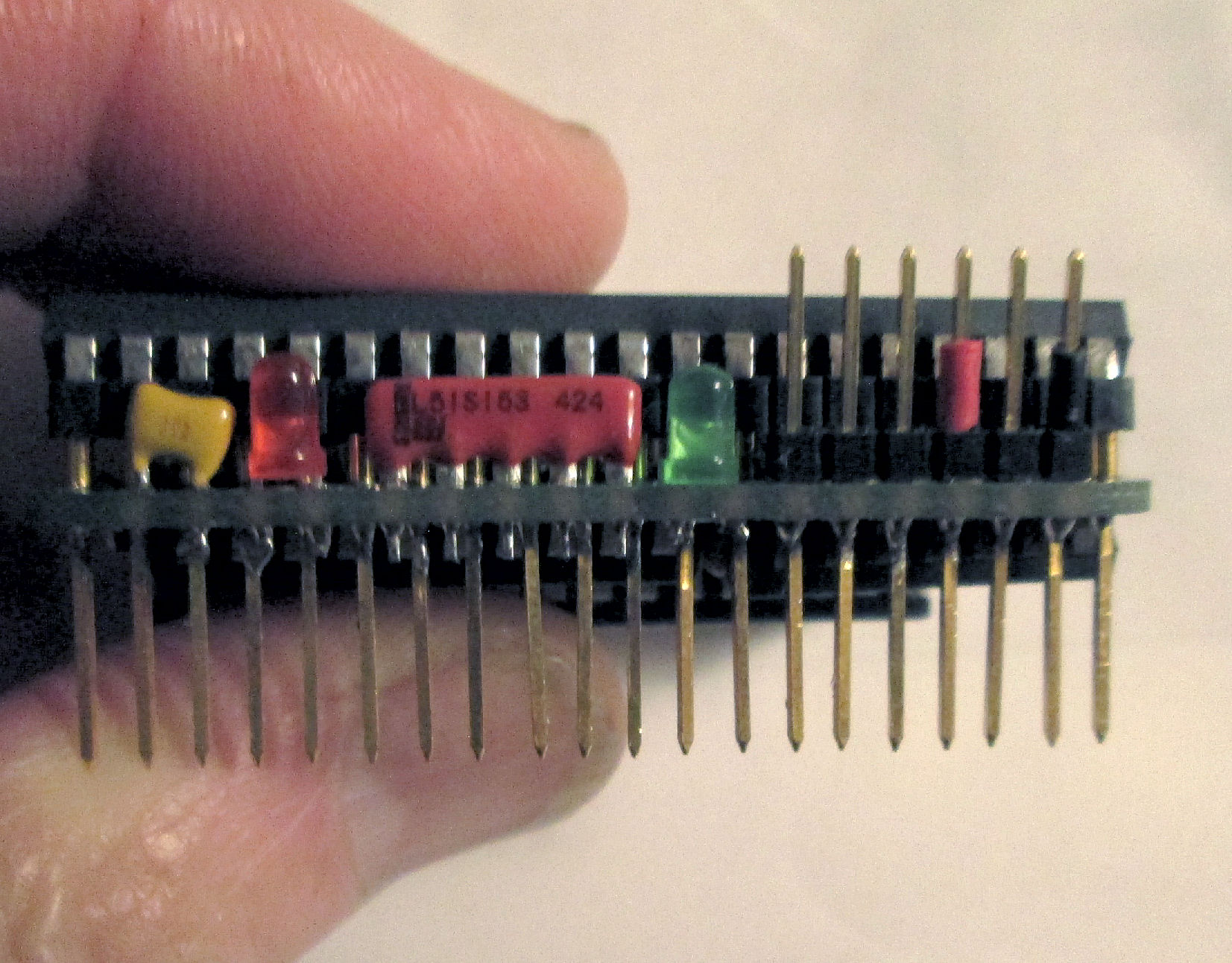
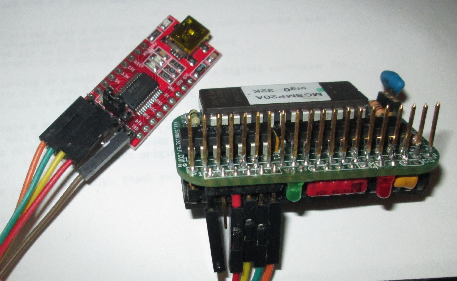
I used a 20 pin header with long pins, for the 20 pins of the 1802 which provide data and I/O signals.
That becomes the I/O expansion for the board. The other 20 pins are a short 20 pin SIP socket.
installed CPU socket RAM already installed
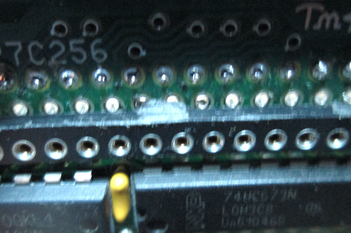
oops repair: I had to pull the 74HC573, installed backwards
Photo checks holes (vias) for damage
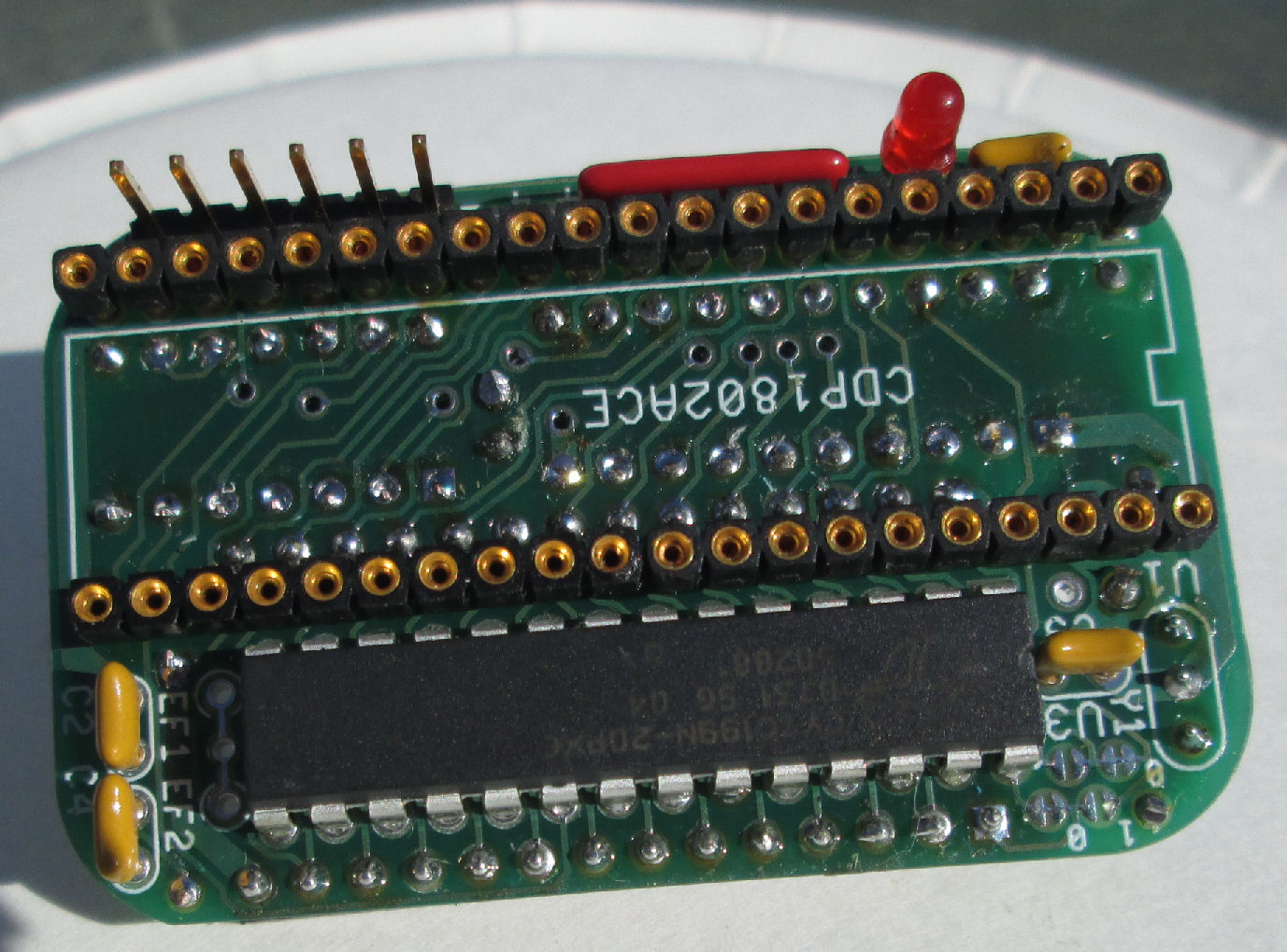
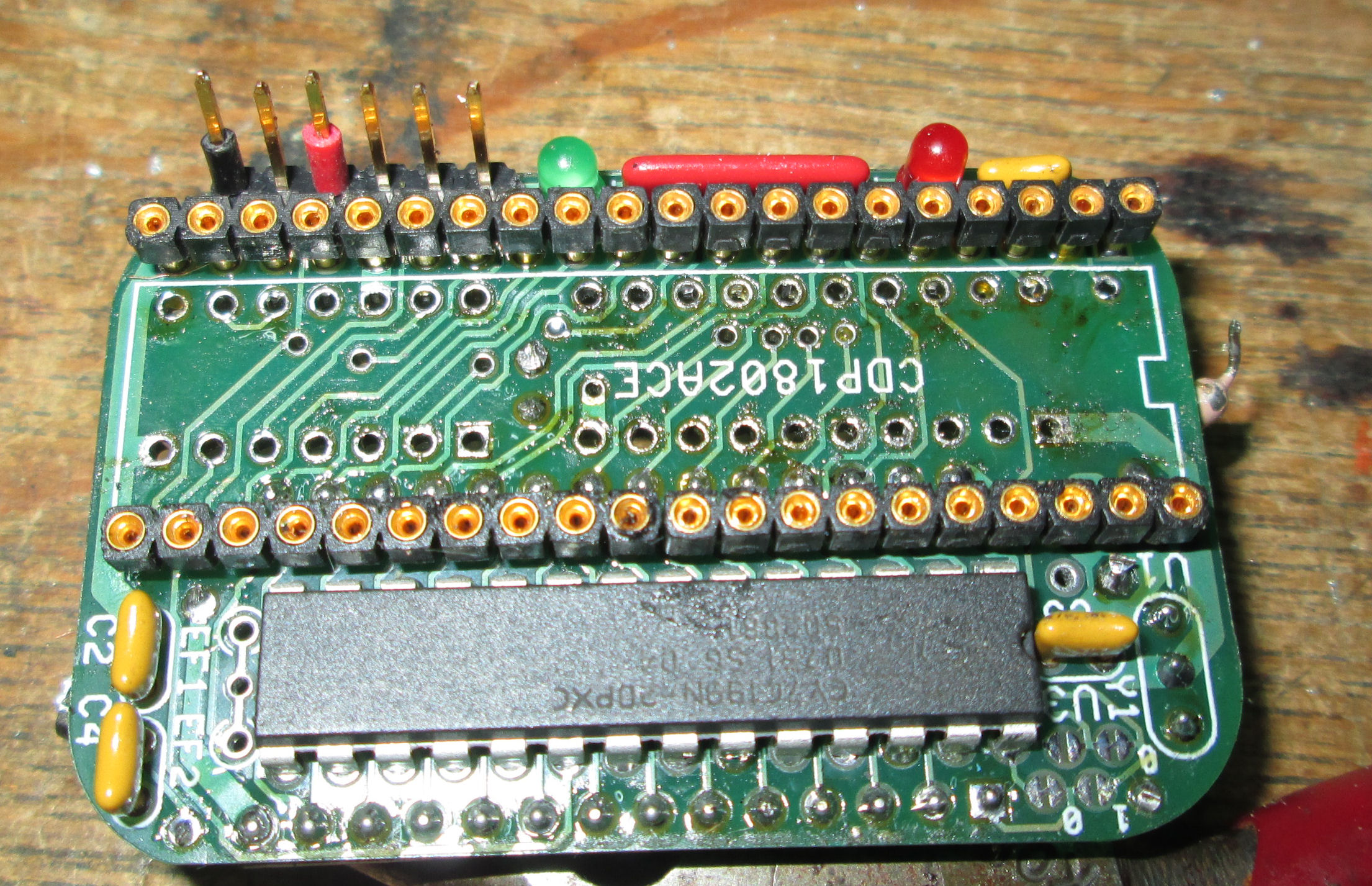
Also see, I put black and red wire-insulation on the 6-pin serial-power connector.
Those mark +5V red, ground black.
had to cut a PC trace this board had a production flaw
installing the ROM socket
another view of the ROM socket
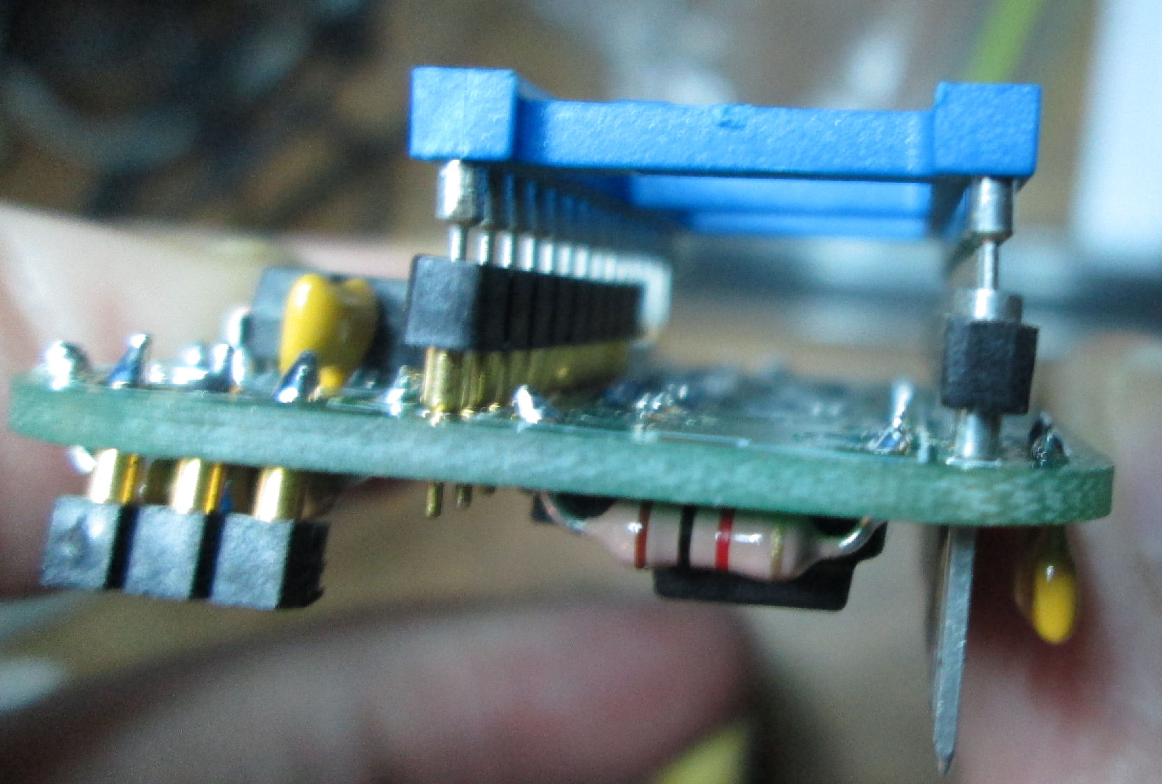
view of the 20-pin header and the 6-pin power/serial header
See again I used red & black wire insulation to mark +5 and ground
completed board on CPU side
completed board on ROM side
The USB/TTL dongle
USB/TTL dongle wired to MemberChip
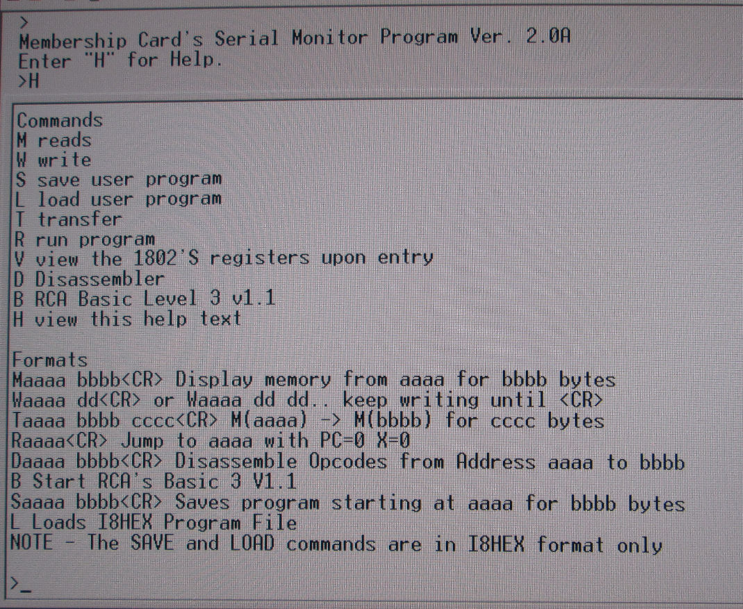
Windows PC display (terminal program) of MemberChip ROM in operation
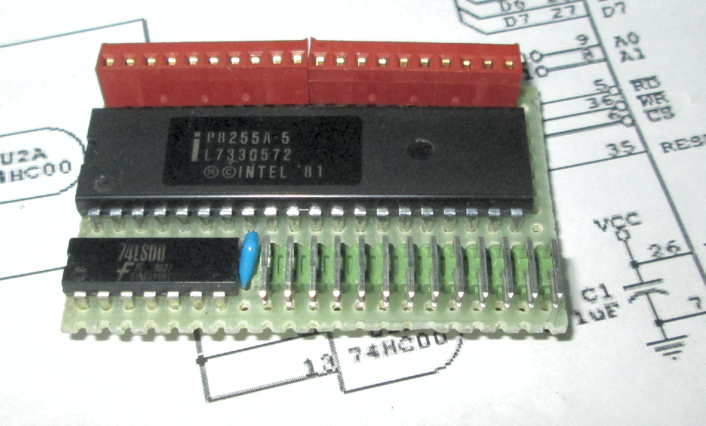
In Feb 2021 I added a second board with an Intel 8255 PIO chip, as suggested by Lee Hart. Here's the schematics for that and other I/O additions. They are wired to the 20-pin side of the 1802 which has data and I/O lines.
![]memberchip]](mchip_appbd.jpg) MemberChip with Intel 8255 PIO on an application board
MemberChip with Intel 8255 PIO on an application board
The 8255 with 74LS00 is one of the "I/O Circuit Examples" schematics in the 1802 MemberChip Card manual.
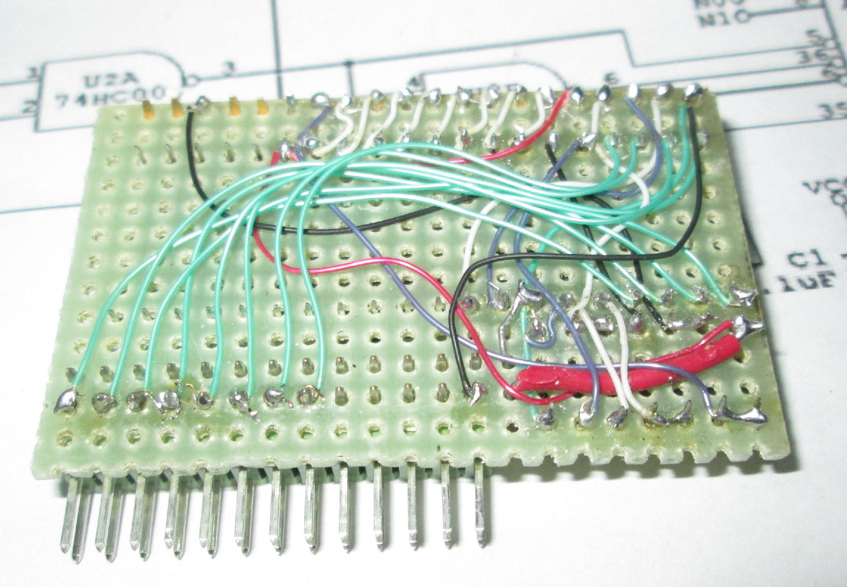
The board was built on a plain protoboard A female IDC socket will match the 20 pin header.
It was hand wired and soldered, no copper needed.
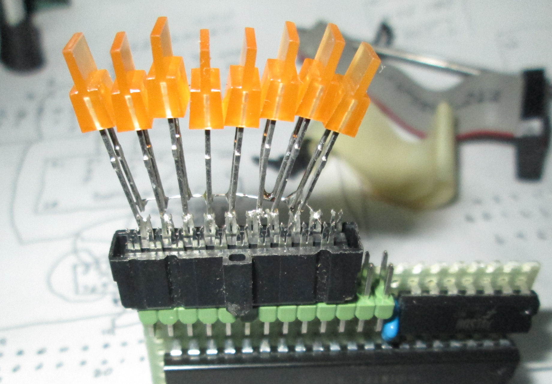
I've only wired the 8255 port A to the 2 X 13 external connector, and I brought out a ground. I've made a test plug with LEDs from an IDC connector. It has some LED's connected from Port A to ground common. I'm hoped the 8255 (not C) has enough pullup current to illuminate the LED's but not so much current that it will need limiting resistors. But Lee Hart said, I should rewire those LEDs as pulldowns from +5 volts. I did that later on. - Herb
Lee Hart said: "The Intel 8255A specs the port A-B-C sink current Iol=1.7mA at 0.45v, so they could easily drive LEDs (with resistors) between an output and VCC. The source current spec is Ioh=2.4v at 200uA, so you'd need a pretty efficient LED if it was connected between an output pin and GND.
"However, they also spec a "darlington" output source current Idar for ports B and C of 1-4mA at 1.5v. So I guess you could connect an LED directly between an output and GND (no resistor) to get enough current for reasonable brightness.
"The MCSMP20A ROM has both BASIC and a monitor. Either one can peek and
poke at the I/O ports. Let me know how it works out!" - Lee Hart
This page and edited content is copyright Herb Johnson (c) 2026. Content provided by others is copyrighted by those authors. Contact Herb at www.retrotechnology.com, an email address is available on that Web page..