![[320 p/s]](sys320_ps1.jpg) Here's the
320 power supply in the 320 chassis. The nameplate reads "MicroEnergy 10-0026 rev 1M,
S/N 3XXX, C/C Feb 1988, 108422 Rev B. Input 110VAC 10A, 230VAC 6A, 50/60Hz. Output: +5.1V 75A, +12.4V 10A, -12.0V 2.5A".
Here's the
320 power supply in the 320 chassis. The nameplate reads "MicroEnergy 10-0026 rev 1M,
S/N 3XXX, C/C Feb 1988, 108422 Rev B. Input 110VAC 10A, 230VAC 6A, 50/60Hz. Output: +5.1V 75A, +12.4V 10A, -12.0V 2.5A".
Last updated Nov 10 2018. Edited by Herb Johnson, (c) Herb Johnson. Contact Herb at www.retrotechnology.com, an email address is on that page..
In Oct-Nov 2018 I disassembled this Intel System 320 Power supply. It's a nonworking supply from a 320 chassis. I have a working System 320 on another Web page. My friend Bill Beech also has the same System 320 chassis with faulty power supply. He and I reverse-engineered the backplane; he drew the schematic.
Here's the
320 power supply in the 320 chassis. The nameplate reads "MicroEnergy 10-0026 rev 1M,
S/N 3XXX, C/C Feb 1988, 108422 Rev B. Input 110VAC 10A, 230VAC 6A, 50/60Hz. Output: +5.1V 75A, +12.4V 10A, -12.0V 2.5A".
The power supply weighs over 12 pounds. It measures 19-3/4 X 7-5/8 X 2-5/8 inches. The longest dimension has an
AC switch which extends an additional 1/2 inch.
![[320 p/s]](sys320_ps2.jpg)
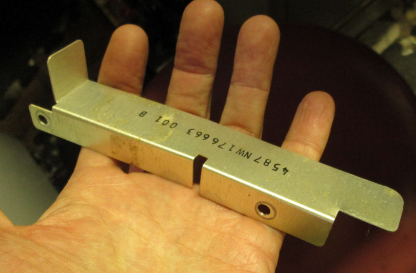
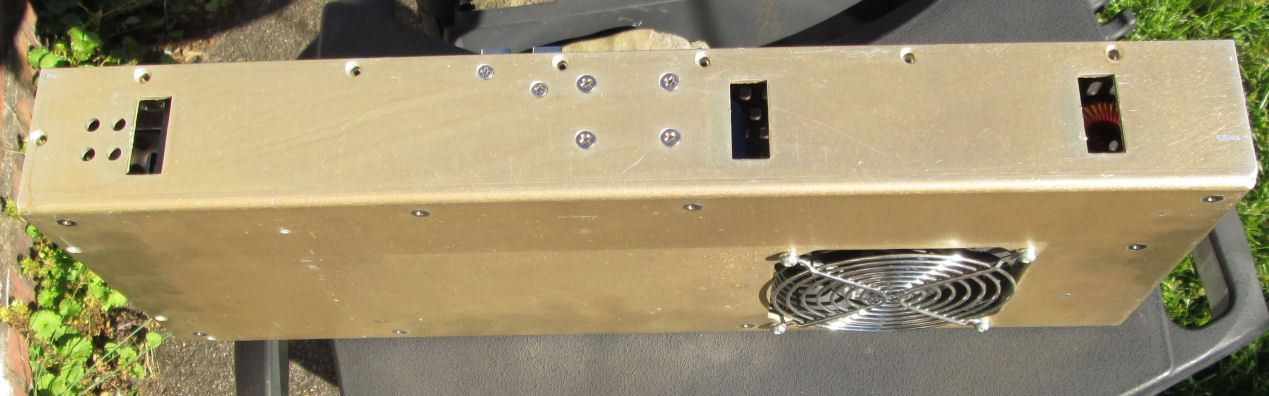
The power supply is held in by multiple screws through the 320 chassis. YOu gotta look hard at it all, to see these screws. Here's another view of the power supply in place. In addition, there's a thin bent-metal plate at the front-end of the power supply, which must be finagled out of the way (technical term). In this view you see one end of that bent-plate, at the front of the 320 chassis and power supply.
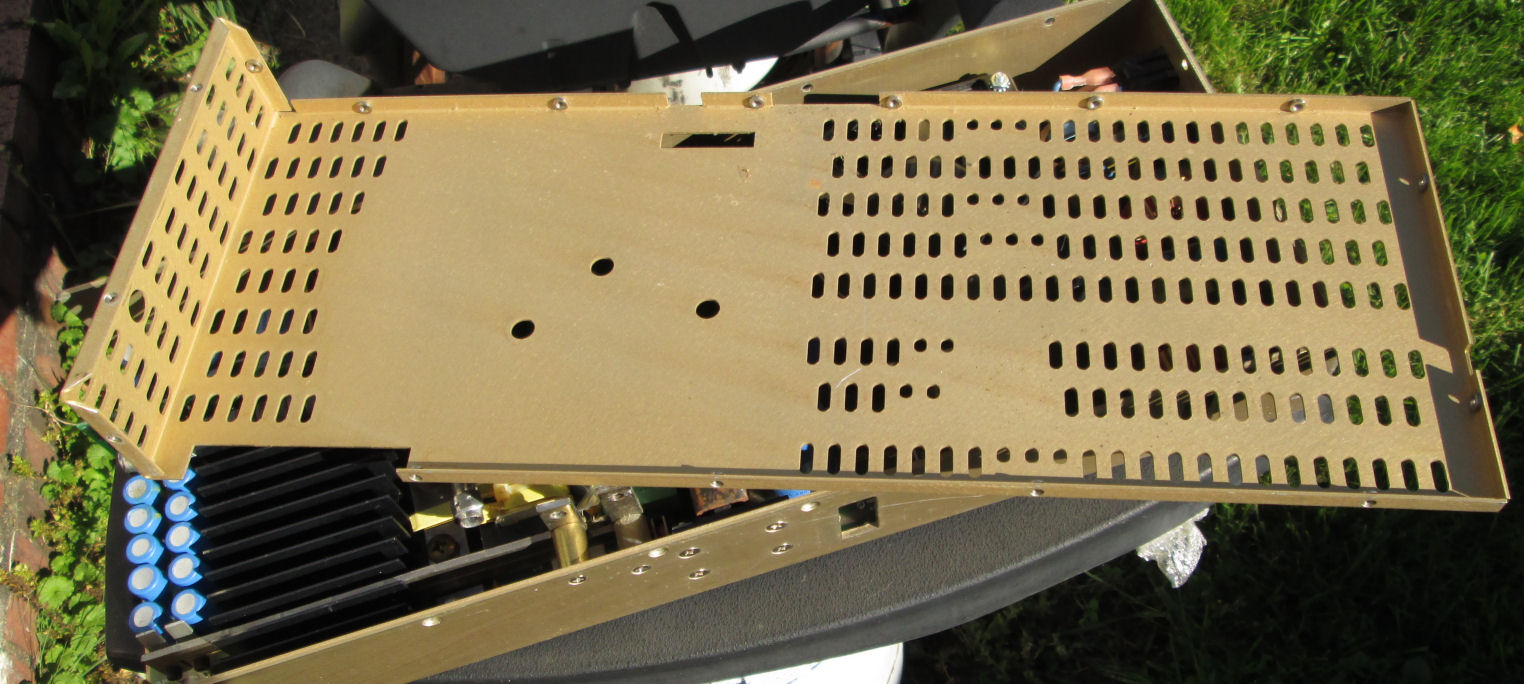
The bottom of the power supply (attached to the bottom of the chassis) has retangular slots. Those are held by L-shaped brackets projecting from the bottom of the chassis, which face "backwards". After removing enough screws, move the unscrewed and loosened power supply toward the front to disengage those brackets. Here's a view of the back corner of the 320 chassis. It shows a large rectangular hole for access to the power supply AC connector and AC power switch; on the floor of the chassis is one of the rectangular brackets facing forward which anchor the power supply to the chassis.
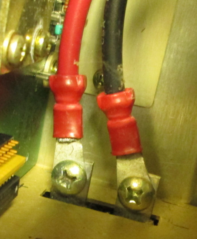
*Caution*, two screws hold posts which support the positive and negative tabs of the +5.1 output, on the side of the power supply. If you loosen those, you must tighten them later, one of them grounds the 5.1V supply to the chassis.
The power supply once removed, provides access to the innards, by removing a cover. The cover amounts to one long side and the end NOT associated with the AC power connector and AC power switch. It's a lot of short screws, along edges of the power supply, to remove that cover.
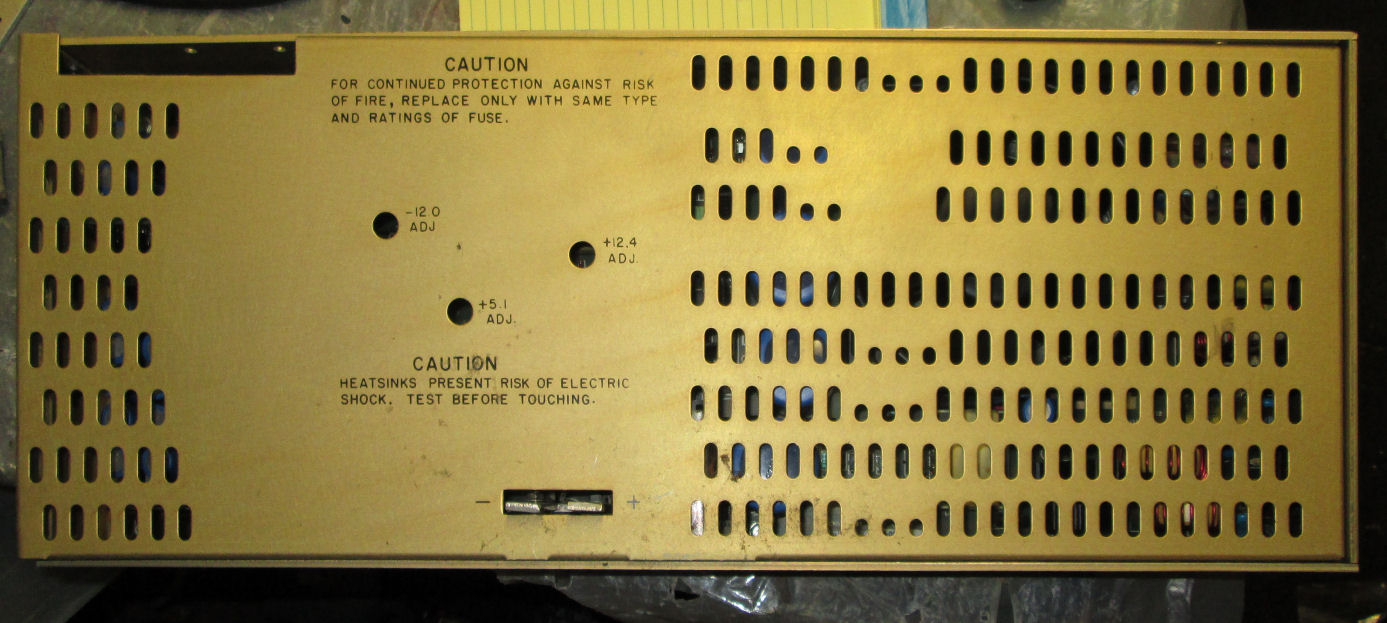
The AC power switch and AC source connector are on the back of the power supply; there's a 110V/220V switch. On the inside side of the p/s, there's access to adjust the three voltages. That is a removable panel, and when removed it reveals the switching power supply circuit board. The board has a tag "10-0038 34XX" and silkscreened "MicroEnergy (C)1986 Rev 1K".
![[320 p/s]](sys320_ps_board.jpg)
With the p/s cover removed, the PC board and components are revealed. The upper left of the photo above is
the connector to the green PC power-distribution board described in the next paragraph. There's an AC fuse inside the power supply, it's a long soldered-in fuse. In the PC board
photo, it's a long white object near the fan toward the AC switch (and various torodial chokes).
On the inside bottom edge of the p/s is the +5.1V connector, a pair of copper tabs with thick wires screwed to the tabs.
![[320 p/s]](sys320_ps_out.jpg)
![[320 p/s]](sys320_ps_sens_1.jpg)
Inside the power supply, the mating connector to distribution connector P1 is labled J15. Pin 1 in the photos is to the far left; that pin corresponds to my pin 1 on my P1 chart above. Disassembly of the power supply will be necessary, to trace pins from its J15. But from these photos, you can see three LM339 (quad op amps) are in use. There's an LM317 (voltage reference). There's test jacks (M4, M3) and a black circular trimpot. These are pretty busy circuits.
Even without a schematic, one can guess the function of these regulatory circuits. Regulated power supplies sometimes include voltage-sensing. If the output voltage drops too low or rises too high, these sensing circuits shutdown the output voltage for safety. The voltage-sense pins on output, provide a low-current path directly to the LOAD of the power supply, to sense voltage without the voltage drop of the high-current lines. So, any malfunction of the power supply, can be either in the current-delivery circuits, or these voltage-sensing circuits. It's important to operate the power supply with some load on high-current lines (+5V, +12V in this case) as a load is expected by the switching-power design.
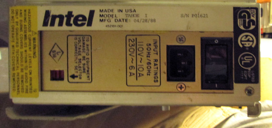
![[320 p/s]](sys320_NCR_pwr1.jpg)
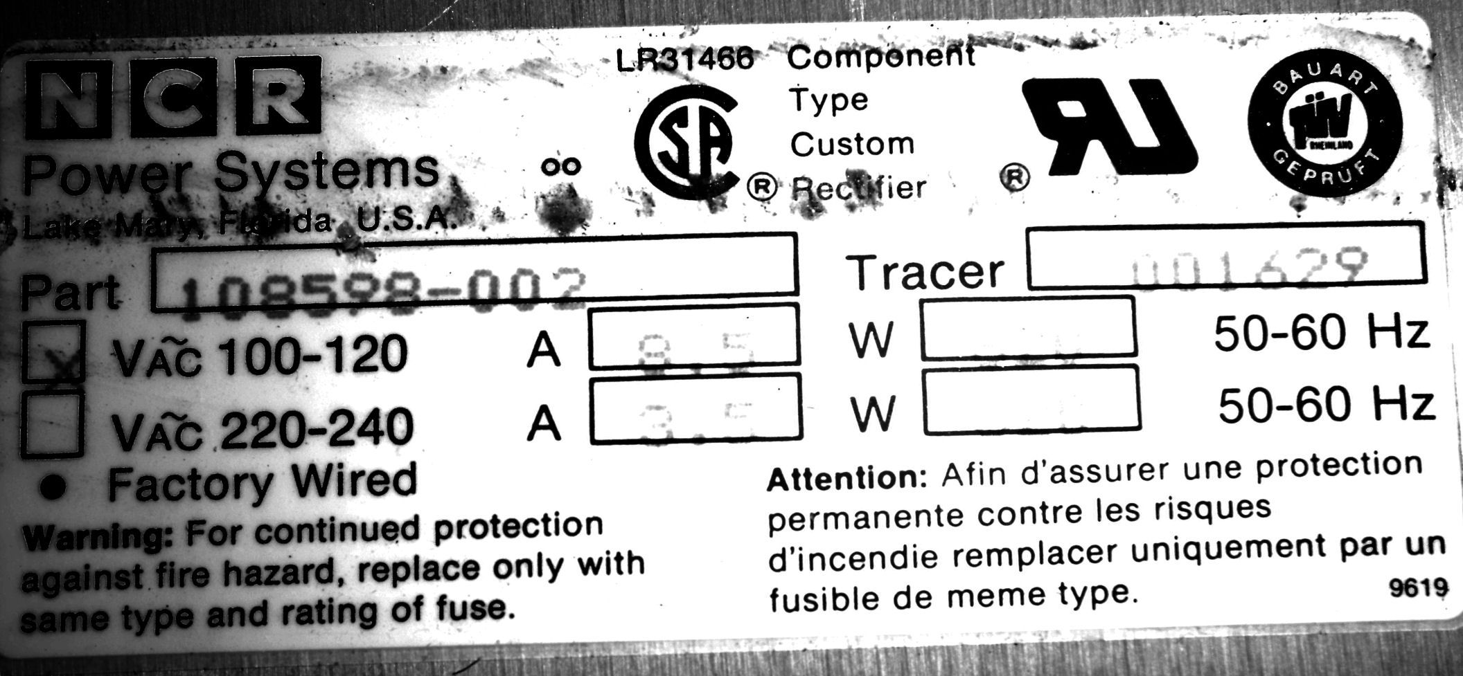
HEre's Bill Beech's version of the System 320 power supply, from NCR Power Systems. The nameplate says it's a part 108598-002, 110-120VAC at 8.5A. Apparently it's adjustable for 220VAC.
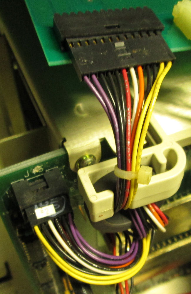
![[320 p/s]](sys320_ps_dist1.jpg) The green PC board has a connector inside the p/s case, held with two screws as identified. The green PC board distributes +5V and +12V power to the various peripherals, and cables other voltages and signals from the power supply (P1) to a local connector (P7). There's a cable J7 to the back of the Multibus backplane (P2/J15). On the distribution board, there's small 7A fuses for each connector at +5V. They look like resistors, they are not
The green PC board has a connector inside the p/s case, held with two screws as identified. The green PC board distributes +5V and +12V power to the various peripherals, and cables other voltages and signals from the power supply (P1) to a local connector (P7). There's a cable J7 to the back of the Multibus backplane (P2/J15). On the distribution board, there's small 7A fuses for each connector at +5V. They look like resistors, they are not
Here's a schematic of the green distribution board, by Bill Beech.Connector P1 is not labled for pinout, I made a guess as to pin-numbering. P1 pin 1 is at the long-side corner of the connector. J7 mates to cable P1; the other end of that cable is P2. P2 plugs into J15 on the backplane. J15 has some pin numbering; J7 is marked at pin 1.
Following is a wiring list of the power supply through the distribution board, cabled to the Multibus backplane. It appears the wire colors for both P1 and P2 are consistent.
P1              J7     P1      P2/J15

1     n/c
2-4   +5V
5-10  GND      11-12  yellow   11-12
11-13 +12V     9-10   black    9-10
14    n/c
15    RESET    8      orange   8
16    ACLO     7      white    7
17    +5SEN    6      red      6
18    SENRET   5      black?   5
19    12VRET   3-4    black    3,4
20    -12V     1-2    violet   2,1
![[320 p/s]](sys320_mobo_full.jpg)
The System 320 has seven Multibus slots. The topmost is designated J7 and J14 for its P1 and P2 connectors respectively. That's the slot for the sbc214 peripheral controller. Below and well seperated is J7/J13, and is intended for the 386 CPU board; subsequent review of the backplane suggests that's the required slot. On my 320 system, the lowest two slots (J1/J8 and J2/J9) have two multiport serial cards installed.
Over the course of a month, Bill Beech and I traced out the backplane and its components and jumpers. Bill drew the schematics. I created a parts list and a list of jumper connections. Here's the 7Z file of those documents.
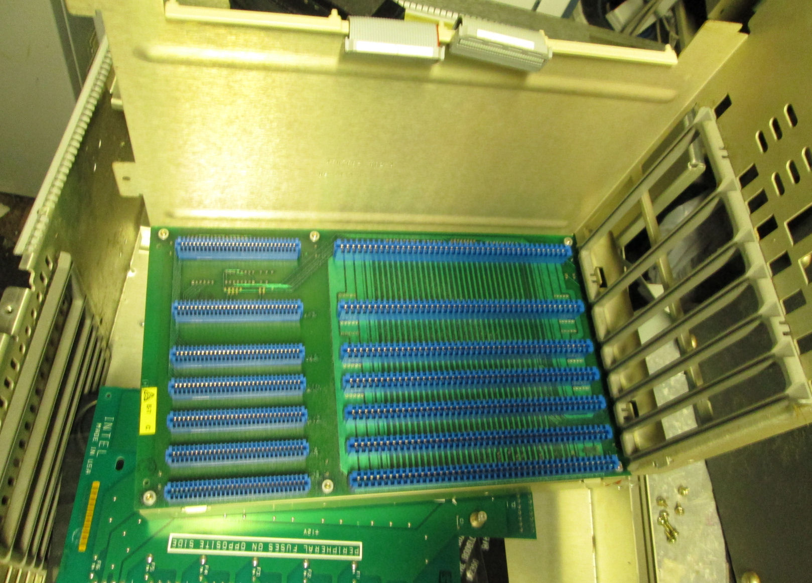
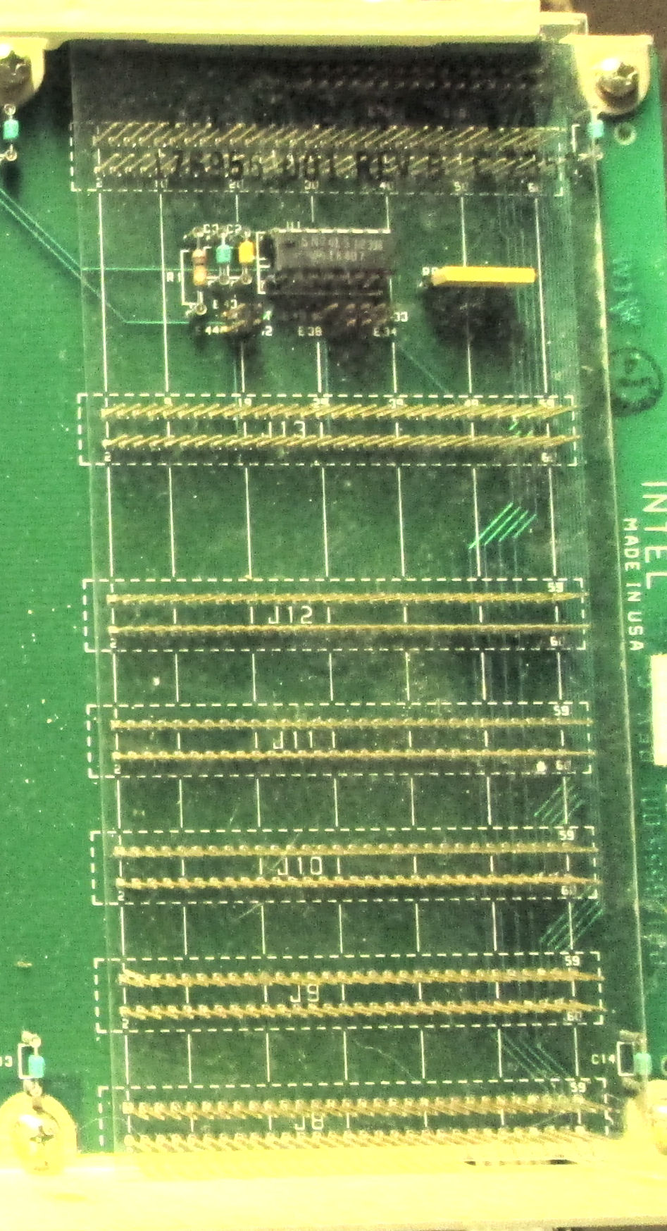
The following are a number of photos of the Multibus backplane. View of entire backplane.
View of the removed backplane assembly. note one set of card-guides remain with the chassis. Several screws hold the backplane assembly down.
In the photo, J15 on the Multibus backplane, is the mating connector to the cable to the power-supply distribution board.
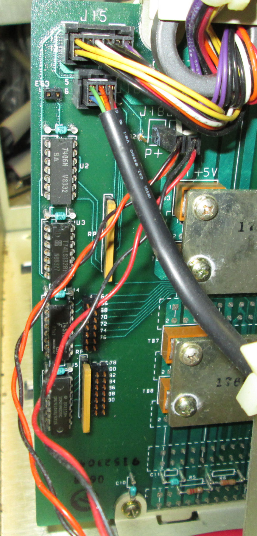
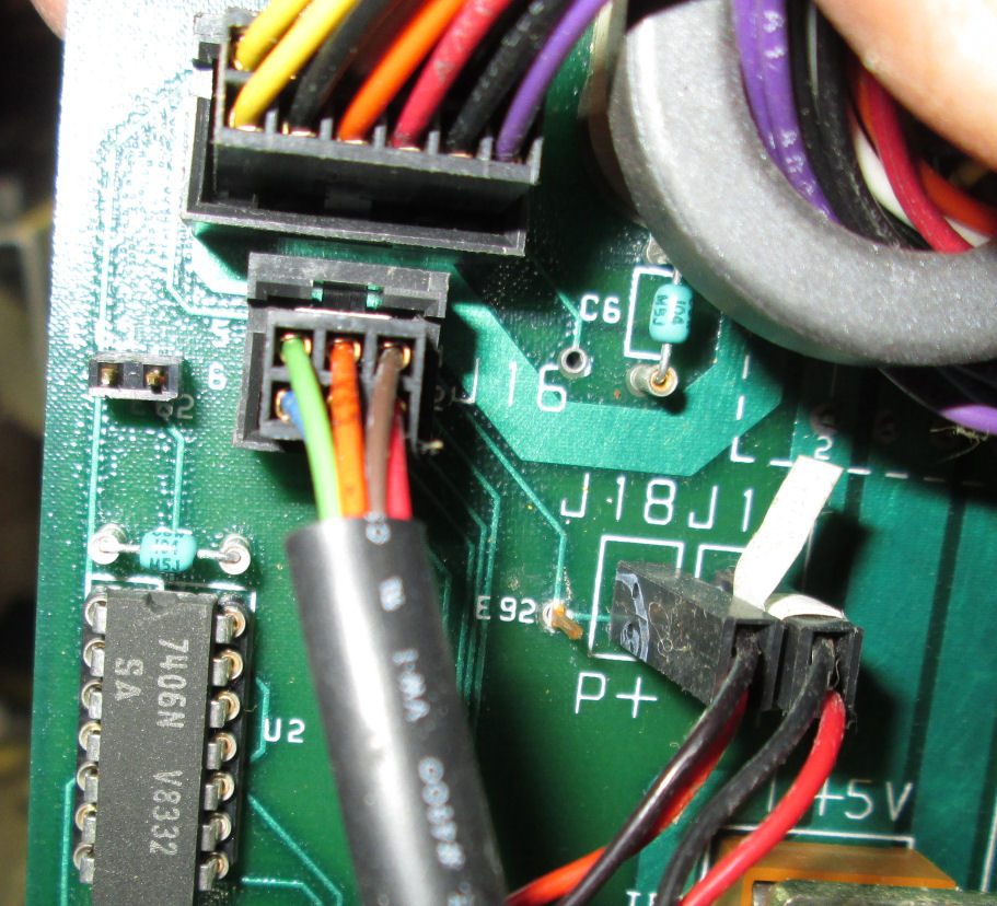
Backplane area with cables and some circuits.
Backplane near cable connections.
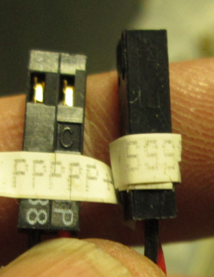
Two red/black cables with paper labels. , which go to P+ J18 and S+ J19 jumpers on backplane. The cables go to two LEDs on the front of the chassis.
View of area near IC's and cable connections.
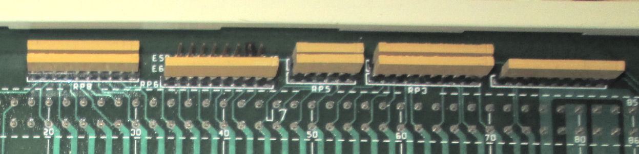
View of edge of backplane showing several SIP resistor packs. . Pin 1 is to
the right in the photo.
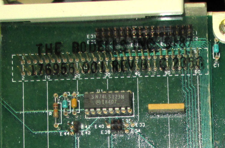
View above P2 area of backplane. Obscured by transparent cover are the
paired row of jumpers all inserted from E1, E2, ....E31, E32. Also shown is a 74LS123 circuit.
This page and edited content is copyright Herb Johnson (c) 2018. Copyright of other contents beyond brief quotes, is held by those authors.
Contact Herb at www.retrotechnology.com, an email address is available on that page..
Contact information:
Herb Johnson
New Jersey, USA
To email @ me, see see my home Web page.